EP1167960A1 - Sealing structure of gas sensor - Google Patents
Sealing structure of gas sensor Download PDFInfo
- Publication number
- EP1167960A1 EP1167960A1 EP01115583A EP01115583A EP1167960A1 EP 1167960 A1 EP1167960 A1 EP 1167960A1 EP 01115583 A EP01115583 A EP 01115583A EP 01115583 A EP01115583 A EP 01115583A EP 1167960 A1 EP1167960 A1 EP 1167960A1
- Authority
- EP
- European Patent Office
- Prior art keywords
- housing
- insulating member
- sealing
- sensor element
- gas sensor
- Prior art date
- Legal status (The legal status is an assumption and is not a legal conclusion. Google has not performed a legal analysis and makes no representation as to the accuracy of the status listed.)
- Granted
Links
- 238000007789 sealing Methods 0.000 title claims description 73
- 229910052751 metal Inorganic materials 0.000 claims abstract description 49
- 239000002184 metal Substances 0.000 claims abstract description 49
- PXHVJJICTQNCMI-UHFFFAOYSA-N Nickel Chemical compound [Ni] PXHVJJICTQNCMI-UHFFFAOYSA-N 0.000 claims abstract description 26
- 229910052759 nickel Inorganic materials 0.000 claims abstract description 13
- 229910000990 Ni alloy Inorganic materials 0.000 claims abstract description 8
- RTAQQCXQSZGOHL-UHFFFAOYSA-N Titanium Chemical compound [Ti] RTAQQCXQSZGOHL-UHFFFAOYSA-N 0.000 claims abstract description 8
- 239000010935 stainless steel Substances 0.000 claims abstract description 8
- 229910001220 stainless steel Inorganic materials 0.000 claims abstract description 8
- 239000010936 titanium Substances 0.000 claims abstract description 8
- 229910052719 titanium Inorganic materials 0.000 claims abstract description 8
- PNEYBMLMFCGWSK-UHFFFAOYSA-N Alumina Chemical compound [O-2].[O-2].[O-2].[Al+3].[Al+3] PNEYBMLMFCGWSK-UHFFFAOYSA-N 0.000 claims description 17
- 238000009413 insulation Methods 0.000 abstract description 48
- 229910052573 porcelain Inorganic materials 0.000 abstract description 48
- 238000012856 packing Methods 0.000 abstract description 33
- 239000000463 material Substances 0.000 description 7
- 238000012360 testing method Methods 0.000 description 6
- 238000004519 manufacturing process Methods 0.000 description 5
- 239000000919 ceramic Substances 0.000 description 4
- 230000007423 decrease Effects 0.000 description 4
- 238000005259 measurement Methods 0.000 description 4
- 239000000843 powder Substances 0.000 description 4
- 238000002485 combustion reaction Methods 0.000 description 3
- 239000000446 fuel Substances 0.000 description 3
- 238000003825 pressing Methods 0.000 description 3
- RYGMFSIKBFXOCR-UHFFFAOYSA-N Copper Chemical compound [Cu] RYGMFSIKBFXOCR-UHFFFAOYSA-N 0.000 description 2
- 229910045601 alloy Inorganic materials 0.000 description 2
- 239000000956 alloy Substances 0.000 description 2
- 229910052802 copper Inorganic materials 0.000 description 2
- 239000010949 copper Substances 0.000 description 2
- YOCUPQPZWBBYIX-UHFFFAOYSA-N copper nickel Chemical compound [Ni].[Cu] YOCUPQPZWBBYIX-UHFFFAOYSA-N 0.000 description 2
- 239000012535 impurity Substances 0.000 description 2
- 238000009434 installation Methods 0.000 description 2
- 238000007747 plating Methods 0.000 description 2
- 230000001681 protective effect Effects 0.000 description 2
- 229910000859 α-Fe Inorganic materials 0.000 description 2
- 229910000881 Cu alloy Inorganic materials 0.000 description 1
- 229910000640 Fe alloy Inorganic materials 0.000 description 1
- 241001481828 Glyptocephalus cynoglossus Species 0.000 description 1
- 229910001030 Iron–nickel alloy Inorganic materials 0.000 description 1
- 229910001182 Mo alloy Inorganic materials 0.000 description 1
- 229910052581 Si3N4 Inorganic materials 0.000 description 1
- 229910000831 Steel Inorganic materials 0.000 description 1
- NINIDFKCEFEMDL-UHFFFAOYSA-N Sulfur Chemical compound [S] NINIDFKCEFEMDL-UHFFFAOYSA-N 0.000 description 1
- 229910052782 aluminium Inorganic materials 0.000 description 1
- XAGFODPZIPBFFR-UHFFFAOYSA-N aluminium Chemical compound [Al] XAGFODPZIPBFFR-UHFFFAOYSA-N 0.000 description 1
- 230000005540 biological transmission Effects 0.000 description 1
- 238000005253 cladding Methods 0.000 description 1
- 239000010941 cobalt Substances 0.000 description 1
- 229910017052 cobalt Inorganic materials 0.000 description 1
- GUTLYIVDDKVIGB-UHFFFAOYSA-N cobalt atom Chemical compound [Co] GUTLYIVDDKVIGB-UHFFFAOYSA-N 0.000 description 1
- PMHQVHHXPFUNSP-UHFFFAOYSA-M copper(1+);methylsulfanylmethane;bromide Chemical compound Br[Cu].CSC PMHQVHHXPFUNSP-UHFFFAOYSA-M 0.000 description 1
- 230000007797 corrosion Effects 0.000 description 1
- 238000005260 corrosion Methods 0.000 description 1
- 239000011521 glass Substances 0.000 description 1
- PCHJSUWPFVWCPO-UHFFFAOYSA-N gold Chemical compound [Au] PCHJSUWPFVWCPO-UHFFFAOYSA-N 0.000 description 1
- 229910052737 gold Inorganic materials 0.000 description 1
- 239000010931 gold Substances 0.000 description 1
- 150000002500 ions Chemical class 0.000 description 1
- 238000003754 machining Methods 0.000 description 1
- 229910000734 martensite Inorganic materials 0.000 description 1
- 239000007769 metal material Substances 0.000 description 1
- 238000000034 method Methods 0.000 description 1
- 239000000203 mixture Substances 0.000 description 1
- 238000012986 modification Methods 0.000 description 1
- 230000004048 modification Effects 0.000 description 1
- DDTIGTPWGISMKL-UHFFFAOYSA-N molybdenum nickel Chemical compound [Ni].[Mo] DDTIGTPWGISMKL-UHFFFAOYSA-N 0.000 description 1
- 229910000510 noble metal Inorganic materials 0.000 description 1
- 238000005498 polishing Methods 0.000 description 1
- 239000005871 repellent Substances 0.000 description 1
- 230000000717 retained effect Effects 0.000 description 1
- HQVNEWCFYHHQES-UHFFFAOYSA-N silicon nitride Chemical compound N12[Si]34N5[Si]62N3[Si]51N64 HQVNEWCFYHHQES-UHFFFAOYSA-N 0.000 description 1
- 239000010959 steel Substances 0.000 description 1
- 229910052717 sulfur Inorganic materials 0.000 description 1
- 239000011593 sulfur Substances 0.000 description 1
- 238000003466 welding Methods 0.000 description 1
Images


Classifications
-
- G—PHYSICS
- G01—MEASURING; TESTING
- G01N—INVESTIGATING OR ANALYSING MATERIALS BY DETERMINING THEIR CHEMICAL OR PHYSICAL PROPERTIES
- G01N27/00—Investigating or analysing materials by the use of electric, electrochemical, or magnetic means
- G01N27/26—Investigating or analysing materials by the use of electric, electrochemical, or magnetic means by investigating electrochemical variables; by using electrolysis or electrophoresis
- G01N27/403—Cells and electrode assemblies
- G01N27/406—Cells and probes with solid electrolytes
- G01N27/407—Cells and probes with solid electrolytes for investigating or analysing gases
- G01N27/4077—Means for protecting the electrolyte or the electrodes
Definitions
- the present invention relates generally to a gas sensor which may be installed in an exhaust system of an internal combustion engine for air-fuel ratio control, and more particularly to an improved structure of a mechanical seal which keeps a reference gas chamber and a gas chamber airtight in a gas sensor.
- Gas sensors are know which are fabricated by inserting a sensor element into an insulation porcelain, mounting the insulation porcelain in a housing, installing a gas cover and an air cover on a front end and a base end of the housing, respectively, and sealing a gap between the insulation porcelain and the housing hermetically. This seal defines a measured gas chamber and an air chamber within the gas sensor.
- the sensor element has a measuring electrode exposed to a gas to be measured and a reference electrode exposed to a reference gas or air and provides a signal in the form of an ion current flowing through the measuring and reference electrodes or a potential difference between the measuring and reference electrodes to determine the concentration of the gas.
- the leakage of the gas from the measured gas chamber to the air chamber will, thus, result in a decrease in accuracy of measuring the concentration of the gas.
- typical gas sensors pack powder material such as talk in the gap between the insulation porcelain and the housing to separate the measured gas chamber and the air chamber hermetically.
- U.S.P. No. 5,795,454 teaches a ceramic ring baked at lower temperature for sealing a gap between a sensor element and a housing to define a measured gas chamber and a reference gas chamber hermetically.
- the ceramic ring usually remains having a certain degree of porosity even after the ceramic ring is installed under high pressure, which may result in lack of airtightness between the sensor element and the housing.
- U.S.P. No. 5,795,454 also discloses use of a lower porosity metallic ring together with the ceramic ring for increasing the degree of the airtightness, however, it will result in increases in fabrication process and manufacturing cost. Moreover, the metallic ring may corrode early depending upon the type of a gas to be measured, which leads to a decrease in degree of the airtightness between the measured gas chamber and the reference gas chamber.
- U.S.P. No. 5,795,454 further discloses a metal seal coated with nickel or copper, however, it requires plating or cladding the whole surface of the metal seal, thus resulting in an increase in manufacturing cost.
- a gas sensor which features a mechanical seal and which may be installed in an exhaust system of an internal combustion engine for air-fuel ratio control.
- the gas sensor comprises: (a) a hollow housing having a sealing shoulder formed on an inner wall thereof; (b) a sensor element having a length which includes a first and a second portion; (c) an insulating member disposed within the housing, retaining the sensor element therein hermetically, the insulating member having a sealing surface formed thereon; and (d) a metal sealing member interposed between the sealing shoulder of the housing and the sealing surface of the insulating member to hermetically define a first chamber in which the first portion of the sensor element is disposed and a second chamber in which the second portion of the sensor element is disposed.
- the metal sealing member is made of at least one of a nickel, a nickel alloy, a titanium, and a stainless steel.
- the first chamber leads to the atmosphere.
- the second chamber is so constructed as to admit a gas to be measured thereinto.
- An air cover is installed on an end of the housing to define the first chamber therein.
- the metal sealing member has a Vickers hardness of 200 or less and a thickness of 0.1mm or more.
- the metal sealing member may be made up of a first layer and a second layer.
- the first layer is in contact with the sealing shoulder of the housing.
- the second layer is in contact with the sealing surface of the insulating member and has a hardness lower than that of the first layer.
- the second layer has a Vickers hardness of 200 or less.
- the sealing surface of the insulating member is tapered.
- the sealing shoulder of the housing is so oriented as to adhere to the sealing surface of the insulating member through the metal sealing member.
- the insulating member is made of an alumina ceramic having an alumina purity of 90% or more.
- the sealing surface of the insulating member has a ten-point average roughness of 10 ⁇ m or less.
- a gas sensor which comprises: (a) a hollow housing having a sealing shoulder formed on an inner wall thereof; (b) a sensor element having a length which includes a first and a second portion; (c) an insulating member disposed within the housing, retaining the sensor element therein hermetically, the insulating member having a sealing surface formed thereon; and (d) a metal sealing member interposed between the sealing shoulder of the housing and the sealing surface of the insulating member to hermetically define a first chamber in which the first portion of the sensor element is disposed and a second chamber in which the second portion of the sensor element is disposed.
- the metal sealing member has a Vickers hardness of 200 or less.
- a gas sensor which comprises: (a) a hollow housing having a sealing shoulder formed on an inner wall thereof; (b) a sensor element having a length which includes a first and a second portion; (c) an insulating member disposed within the housing, retaining the sensor element therein hermetically, the insulating member having formed thereon a sealing surface having a ten-point average roughness of 10 ⁇ m or less; and (d) a metal sealing member interposed between the sealing shoulder of the housing and the sealing surface of the insulating member to hermetically define a first chamber in which the first portion of the sensor element is disposed and a second chamber in which the second portion of the sensor element is disposed.
- the sealing surface of the insulating member is polished.
- the sealing surface of the insulating member may alternatively be plated.
- the insulating member is made of an alumina ceramic having an alumina purity of 90% or more.
- a gas sensor which comprises: (a) a hollow housing having a sealing shoulder formed on an inner wall thereof; (b) a sensor element having a length which includes a first and a second portion; (c) an insulating member disposed within the housing, retaining the sensor element therein hermetically, the insulating member having a sealing surface formed thereon, the insulating member being made of an alumina ceramic having an alumina purity of 90% or more; and (d) a metal sealing member interposed between the sealing shoulder of the housing and the sealing surface of the insulating member to hermetically define a first chamber in which the first portion of the sensor element is disposed and a second chamber in which the second portion of the sensor element is disposed.
- a gas sensor 1 according to the first embodiment of the invention which may be employed in an air-fuel ratio control system for automotive vehicles to measure the concentration of a component such as NOx, CO, HC, or O 2 contained in exhaust gasses of the engine.
- the gas sensor 1 generally includes a sensor element 15, a first insulation porcelain 21, a second insulation porcelain 22, a hollow cylindrical housing 10, and an air cover 12.
- the sensor element 15 is made of a laminated plate.
- U.S.P. No. 5,573,650, issued on November 12, 1996 to Fukaya et al. teaches a typical laminated sensor element, disclosure of which is incorporated herein by reference.
- the first insulation porcelain 21 is fitted within the housing 10 and holds therein the sensor element 15 through a glass sealing member 219.
- the second insulation porcelain 22 is mounted on the first insulation porcelain 21 and surrounds a base portion of the sensor element 15.
- the air cover 12 is installed at an end thereof on the housing 10 and surrounds the second insulation porcelain 22 to define an air chamber 142.
- the second insulation porcelain 22 is made of a hollow cylindrical insulating member and has disposed therein four leads 16 (only two are shown for the simplicity of illustration) each of which is made of a wire folded elastically to make an electric contact at one end with an electrode terminal (not shown) formed on the sensor element 15.
- the leads 16 extend at the other end through holes formed in an end of the second insulation porcelain 22 and connect with four leads 18 through connectors 17, respectively, for transmission of sensor signals between the sensor element 15 and an external device and supply of electric power to a heater installed on the sensor element 15.
- the gas sensor 1 also includes a protective cover assembly 13 consisting of an outer cover 131 and an inner cover 132.
- the protective cover assembly 13 is installed in a head of the housing 10 to define a gas chamber 141 into which a gas to be measured is admitted through gas holes 130 formed in the outer and inner covers 131 and 132.
- the first insulation porcelain 21, as clearly shown in Fig. 2, has an annular shoulder 211 and a chamfered surface 214 formed on a head thereof.
- the chamfered surface 214 faces an inner shoulder 102, as shown in Fig. 1, formed in the housing 10 when the first insulation porcelain 21 is fitted within the housing 10.
- the shoulder 211 has a tapered surface 213 which is placed through a metal packing ring 11 on a seat surface 103 formed on an annular shoulder 101 on an inner wall of the housing 10.
- a gap between the housing 10 and the first insulation porcelain 21 is sealed hermetically by the metal packing ring 11 to keep the air chamber 142 and the gas chamber 141 airtight.
- the seat surface 103 is inclined downward, as viewed in Fig. 1, to increase the degree of adhesion to the tapered surface 213 through the metal packing ring 11.
- the metal packing ring 11 is, as will be described later in detail, made of a pure nickel.
- the air cover 12 is, as described above, fitted on the base end of the housing 10.
- An outer cover 121 is provided around the air cover 12 and staked or crimped to retain a water-repellent filter 122 on the periphery of the air cover 12.
- the air cover 12 and the outer cover 121 have formed therein air vents 120 through which air is admitted into the air chamber 142.
- the air cover 12, as clearly shown in Fig. 1, has a shoulder 129 to define a small-diameter portion and a large-diameter portion.
- a disc spring 220 is disposed between the shoulder 129 and an end of the second insulation porcelain 22 to elastically urge the second insulation porcelain 22 into constant engagement with the first insulation porcelain 21 to increase the degree of airtightness provided by the metal packing ring 11.
- An insulating holder 23 made of rubber is disposed inside the small-diameter portion of the air cover 12.
- the sensor element 15 as described above, has a heater built therein which heats the sensor element 15 up to a temperature required for the sensor element 15 to be sensitive to a gas to be measured correctly.
- the sensor element 15 has formed thereon four electrode terminals two of which are used for outputting sensor signals and the others for supply of electric power to the heater.
- the electrode terminals are connected electrically with ends of the leads 16 in an illustrated manner, respectively.
- the leads 16 extend through the holes formed in the end wall of the second insulation porcelain 22 and are inserted into the connectors 17, respectively.
- the connectors 17 are coupled with the leads 18 retained in holes formed in the insulating holder 23.
- the first insulation porcelain 21 is, as described above, carried at the shoulder 211 on the shoulder 101 of the housing 10 through the metal packing ring 11.
- the metal packing ring 11 is made of a pure nickel of a 99% purity containing a small amount of impurities such as cobalt etc.
- the metal packing ring 11, therefore, has a highly dense surface which ensures a high degree of airtightness between the second insulation porcelain 21 and the housing 10.
- the metal packing ring 11 may alternatively be made of a nickel alloy, a titanium, a stainless steel, or a mixture of at least two of them (including a pure nickel).
- nickel alloy a nickel-iron alloy, a nickel-copper alloy, a nickel-chrome alloy, a nickel-chrome-iron alloy, a nickel-molybdenum alloy, or a nickel base superheat-resistant alloy may be used.
- titanium a pure titanium containing impurities of 1% or less such as that specified in one of Japanese Industrial Standard (JIS) Class 1 to Class 3 or one of ASTMG1 to ASTMG4 in U.S. is preferable.
- JIS Japanese Industrial Standard
- ASTMG1 to ASTMG4 one of ASTMG1 to ASTMG4 in U.S.
- stainless steel a martensitic, a ferrite, an austenitic, or an austenite-ferrite steel may be used.
- the gas sensor 1 In a case where the gas sensor 1 is installed in an exhaust system of an automotive internal combustion engine to measure the concentration of a component such as NOx, CO, HC, or O 2 contained in exhaust gasses of the engine, the gas sensor 1 is subjected to intense heat and exposed to sulfur, therefore, a nickel or nickel alloy which has a high corrosion-resistance is preferable.
- the nickel or nickel alloy is inexpensive as compared with noble metals and allows the gas sensor 1 to be manufactured at low costs.
- the metal packing ring 11 has a Vickers hardness of at least 200Hv or less, preferably 150Hv or less. In this embodiment, the hardness of the metal packing ring 11 is about 70Hv. If the hardness of the metal packing ring 11 is more than 200Hv, the shoulder 211 of the first insulation porcelain 21 is required to be pressed against the shoulder 101 of the housing 10 under high pressure to nip the metal packing ring 11 firmly, which may cause damage to the first insulation porcelain 21. If the first insulation porcelain 21 is made of a material capable of withstanding such a high pressure, it will result in an increase in manufacturing costs.
- the metal packing ring 11 has a thickness of 0.1mm or more (0.4mm in this embodiment). If it is less than 0.1mm, the metal packing ring 11 undergoes corrosion early, thus resulting in a decrease in service life thereof. Additionally, the machining of the metal packing ring 11 is difficult, thus resulting in an increase in manufacturing costs.
- Fig. 3 shows a second embodiment of the invention which is different from the first embodiment in that the metal packing ring 11 is made of two layers: a first layer 111 and a second layer 112. Other arrangements are identical, and explanation thereof in detail will be omitted here.
- the first layer 111 and the second layer 112 are, as clearly shown in Fig. 3, laid to overlap each other.
- the first layer 111 is made of the same material as that of the metal packing ring 11 of the first embodiment.
- the second layer 112 is made of a material having a hardness lower than that of the first layer 111.
- the first layer 111 is made of a pure nickel or a pure titanium.
- the second layer 112 is made of a stainless steel which is softer in mechanical property than the first layer 111. The reason for this will be discussed below.
- the housing 11 is usually made of an easy-to-machine metallic material which has a relatively lower hardness.
- the installation of the first insulation porcelain 21 in the housing 11 is accomplished by placing the first insulation porcelain 21 in which the sensor element 15 is fitted within the housing 11 through the metal packing ring 11, putting the second insulation porcelain 22 within which the leads 16 are disposed in the air cover 12 together with the disc spring 220, fitting the air cover 12 on the base portion of the housing 11, and welding the air cover 12 to the base portion of the housing 11 while pressing the air cover 12 downward, as viewed in Fig. 1, to have the tapered surface 213 of the first insulation porcelain 211 adhere to the seat surface 103 of the housing 11 through the metal packing ring 11.
- the pressing the first insulation porcelain 21 against the housing 10 will cause the seat surface 103 of the housing 10 to be deformed, thereby increasing the degree of adhesion of the first layer 111 to the seat surface 103 of the housing 10.
- the first insulation porcelain 22 has a relatively higher hardness. The pressing the first insulation porcelain 21 against the housing 10 will, therefore, cause the second layer 112 softer than the first layer 111 to be deformed, thereby increasing the degree of adhesion of the second layer 112 to the tapered surface 213 of the first insulation porcelain 21.
- Fig. 4 shows a gas sensor 1 according to the third embodiment of the invention.
- the metal packing ring 11 is disposed between the chamfered surface 214 formed on the head of the first insulation porcelain 21 and the annular shoulder 102 formed on the inner wall of the housing 10, thereby keeping the air chamber 142 and the gas chamber 141 airtight.
- Other arrangement are identical with those in the first embodiment, and explanation thereof in detail will be omitted here.
- the first insulation porcelain 21 may be made of an alumina ceramic having a 90% or more purity (preferably, 92% or more, more preferably, 95% or more)
- the first insulation porcelain 21 is made of an alumina ceramic of a purity of 98%.
- the tapered surface 213 of the first insulation porcelain 21 on which the metallic packing ring 11 is placed have a relative roughness of 10 ⁇ m or less (preferably, 2 ⁇ m) as expressed by taking an average of ten samples (which is also referred to as a ten-point average), thereby providing a highly airtight seal between the first insulation porcelain 21 and the housing 10.
- the above roughness of the tapered surface 213 may be derived by polishing or plating the metal packing ring 11 with nickel, copper, or gold.
- the first insulation porcelain 21 may alternatively be made of a silicon nitride or an aluminum nitride.
- the metal packing ring 11 may be made of a stainless steel plated with a nickel-copper.
- Leakage tests were performed using a test device, as shown in Fig. 6, to find a relation between the roughness of the tapered surface 213 of the first insulation porcelain 21 and a gas leakage.
- the test device includes a leakage measuring unit 72 equipped with an air regulator valve 71 and a gas sensor mount base 74.
- the leakage measuring unit 72 and the gas sensor mount base 74 are connected through a valve 73.
- the head of the gas sensor 1 is installed in an air cavity 740 of the gas sensor mount base 74 hermetically through a rubber seal 741.
- the roughness of test pieces of the first insulation porcelain 21 made from alumina of different purities were measured to find a relation between the roughness of the tapered surface 213 and the alumina purity of the first insulation porcelain 21.
- the measurement of roughness of each of the test pieces was made three times over a length of 0.8mm in accordance with JISB0601 using a needle whose tip angle is 90° and radius of curvature at the tip is 2 ⁇ m.
- the results of the measurements are shown in a graph of Fig. 7. The graph shows that when the purity of alumina exceeds 90%, the roughness of the tapered surface 213 of the first insulation porcelain 21 decreases greatly.
- An improved structure of a mechanical seal for keeping a gas chamber and a reference gas chamber airtight in a sensor body is disposed between a shoulder formed on an inner wall of a housing of the sensor body and a tapered surface of an insulation porcelain installed in the housing to define the gas chamber and the reference gas chamber hermetically.
- the packing ring is formed by a metal plate which has a thickness of 0.1mm or more and a Vickers hardness of 200 or more and which is made of at least one of a nickel, a nickel alloy, a titanium, and a stainless steel.
Landscapes
- Chemical & Material Sciences (AREA)
- Life Sciences & Earth Sciences (AREA)
- Health & Medical Sciences (AREA)
- Physics & Mathematics (AREA)
- Chemical Kinetics & Catalysis (AREA)
- Electrochemistry (AREA)
- Molecular Biology (AREA)
- Analytical Chemistry (AREA)
- Biochemistry (AREA)
- General Health & Medical Sciences (AREA)
- General Physics & Mathematics (AREA)
- Immunology (AREA)
- Pathology (AREA)
- Measuring Oxygen Concentration In Cells (AREA)
Abstract
Description
- The present invention relates generally to a gas sensor which may be installed in an exhaust system of an internal combustion engine for air-fuel ratio control, and more particularly to an improved structure of a mechanical seal which keeps a reference gas chamber and a gas chamber airtight in a gas sensor.
- Gas sensors are know which are fabricated by inserting a sensor element into an insulation porcelain, mounting the insulation porcelain in a housing, installing a gas cover and an air cover on a front end and a base end of the housing, respectively, and sealing a gap between the insulation porcelain and the housing hermetically. This seal defines a measured gas chamber and an air chamber within the gas sensor.
- The sensor element has a measuring electrode exposed to a gas to be measured and a reference electrode exposed to a reference gas or air and provides a signal in the form of an ion current flowing through the measuring and reference electrodes or a potential difference between the measuring and reference electrodes to determine the concentration of the gas. The leakage of the gas from the measured gas chamber to the air chamber will, thus, result in a decrease in accuracy of measuring the concentration of the gas. In order to avoid this problem, typical gas sensors pack powder material such as talk in the gap between the insulation porcelain and the housing to separate the measured gas chamber and the air chamber hermetically.
- The use of powder material such as talk, however, results in an economical disadvantage that the pressure required to pack the powder material and the amount of powder material must be controlled finely and precisely.
- In order to alleviate such a drawback, bulk material-made packing is proposed as a sealing member. For example, U.S.P. No. 5,795,454 teaches a ceramic ring baked at lower temperature for sealing a gap between a sensor element and a housing to define a measured gas chamber and a reference gas chamber hermetically. The ceramic ring, however, usually remains having a certain degree of porosity even after the ceramic ring is installed under high pressure, which may result in lack of airtightness between the sensor element and the housing.
- U.S.P. No. 5,795,454 also discloses use of a lower porosity metallic ring together with the ceramic ring for increasing the degree of the airtightness, however, it will result in increases in fabrication process and manufacturing cost. Moreover, the metallic ring may corrode early depending upon the type of a gas to be measured, which leads to a decrease in degree of the airtightness between the measured gas chamber and the reference gas chamber.
- U.S.P. No. 5,795,454 further discloses a metal seal coated with nickel or copper, however, it requires plating or cladding the whole surface of the metal seal, thus resulting in an increase in manufacturing cost.
- It is therefore a principal object of the invention to avoid the disadvantages of the prior art.
- It is another object of the invention to provide an improved structure of a gas sensor which provides a mechanical seal required to keep a reference gas chamber and a gas chamber in the gas sensor airtight highly.
- According to the first aspect of the invention, there is provided a gas sensor which features a mechanical seal and which may be installed in an exhaust system of an internal combustion engine for air-fuel ratio control. The gas sensor comprises: (a) a hollow housing having a sealing shoulder formed on an inner wall thereof; (b) a sensor element having a length which includes a first and a second portion; (c) an insulating member disposed within the housing, retaining the sensor element therein hermetically, the insulating member having a sealing surface formed thereon; and (d) a metal sealing member interposed between the sealing shoulder of the housing and the sealing surface of the insulating member to hermetically define a first chamber in which the first portion of the sensor element is disposed and a second chamber in which the second portion of the sensor element is disposed. The metal sealing member is made of at least one of a nickel, a nickel alloy, a titanium, and a stainless steel.
- In the preferred mode of the invention, the first chamber leads to the atmosphere. The second chamber is so constructed as to admit a gas to be measured thereinto.
- An air cover is installed on an end of the housing to define the first chamber therein.
- The metal sealing member has a Vickers hardness of 200 or less and a thickness of 0.1mm or more.
- The metal sealing member may be made up of a first layer and a second layer. The first layer is in contact with the sealing shoulder of the housing. The second layer is in contact with the sealing surface of the insulating member and has a hardness lower than that of the first layer. The second layer has a Vickers hardness of 200 or less.
- The sealing surface of the insulating member is tapered. The sealing shoulder of the housing is so oriented as to adhere to the sealing surface of the insulating member through the metal sealing member.
- The insulating member is made of an alumina ceramic having an alumina purity of 90% or more.
- The sealing surface of the insulating member has a ten-point average roughness of 10 µm or less.
- According to the second aspect of the invention, there is provided a gas sensor which comprises: (a) a hollow housing having a sealing shoulder formed on an inner wall thereof; (b) a sensor element having a length which includes a first and a second portion; (c) an insulating member disposed within the housing, retaining the sensor element therein hermetically, the insulating member having a sealing surface formed thereon; and (d) a metal sealing member interposed between the sealing shoulder of the housing and the sealing surface of the insulating member to hermetically define a first chamber in which the first portion of the sensor element is disposed and a second chamber in which the second portion of the sensor element is disposed. The metal sealing member has a Vickers hardness of 200 or less.
- According to the third aspect of the invention, there is provided a gas sensor which comprises: (a) a hollow housing having a sealing shoulder formed on an inner wall thereof; (b) a sensor element having a length which includes a first and a second portion; (c) an insulating member disposed within the housing, retaining the sensor element therein hermetically, the insulating member having formed thereon a sealing surface having a ten-point average roughness of 10µm or less; and (d) a metal sealing member interposed between the sealing shoulder of the housing and the sealing surface of the insulating member to hermetically define a first chamber in which the first portion of the sensor element is disposed and a second chamber in which the second portion of the sensor element is disposed.
- In the preferred mode of the invention, the sealing surface of the insulating member is polished.
- The sealing surface of the insulating member may alternatively be plated.
- The insulating member is made of an alumina ceramic having an alumina purity of 90% or more.
- According to the fourth aspect of the invention, there is provided a gas sensor which comprises: (a) a hollow housing having a sealing shoulder formed on an inner wall thereof; (b) a sensor element having a length which includes a first and a second portion; (c) an insulating member disposed within the housing, retaining the sensor element therein hermetically, the insulating member having a sealing surface formed thereon, the insulating member being made of an alumina ceramic having an alumina purity of 90% or more; and (d) a metal sealing member interposed between the sealing shoulder of the housing and the sealing surface of the insulating member to hermetically define a first chamber in which the first portion of the sensor element is disposed and a second chamber in which the second portion of the sensor element is disposed.
- The present invention will be understood more fully from the detailed description given hereinbelow and from the accompanying drawings of the preferred embodiments of the invention, which, however, should not be taken to limit the invention to the specific embodiments but are for the purpose of explanation and understanding only.
- In the drawings:
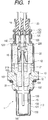
- Fig. 1 is a longitudinal sectional view which shows a gas sensor according to the first embodiment of the invention;
- Fig. 2 is a partially sectional view which shows installation of a metal packing ring between an insulation porcelain and a housing;
- Fig. 3 is a partially sectional view which shows a metal packing ring according to the second embodiment of the invention;
- Fig. 4 is a partially longitudinal sectional view which shows a gas sensor according to the third embodiment of the invention;
- Fig. 5 is a graph which shows a relation between the roughness of a packing ring-mounted surface of a first insulation porcelain and a gas leakage;
- Fig. 6 is a view which shows a leakage test device; and
- Fig. 7 is a graph which shows a relation between the roughness of a packing ring-mounted surface of a first insulation porcelain and an aluminum purity of the first insulation porcelain.
-
- Referring to the drawings, wherein like reference numbers refer to like parts in several views, particularly to Figs. 1 and 2, there is shown a
gas sensor 1 according to the first embodiment of the invention which may be employed in an air-fuel ratio control system for automotive vehicles to measure the concentration of a component such as NOx, CO, HC, or O2 contained in exhaust gasses of the engine. - The
gas sensor 1 generally includes asensor element 15, afirst insulation porcelain 21, asecond insulation porcelain 22, a hollowcylindrical housing 10, and anair cover 12. Thesensor element 15 is made of a laminated plate. U.S.P. No. 5,573,650, issued on November 12, 1996 to Fukaya et al. teaches a typical laminated sensor element, disclosure of which is incorporated herein by reference. Thefirst insulation porcelain 21 is fitted within thehousing 10 and holds therein thesensor element 15 through aglass sealing member 219. Thesecond insulation porcelain 22 is mounted on thefirst insulation porcelain 21 and surrounds a base portion of thesensor element 15. Theair cover 12 is installed at an end thereof on thehousing 10 and surrounds thesecond insulation porcelain 22 to define anair chamber 142. - The
second insulation porcelain 22 is made of a hollow cylindrical insulating member and has disposed therein four leads 16 (only two are shown for the simplicity of illustration) each of which is made of a wire folded elastically to make an electric contact at one end with an electrode terminal (not shown) formed on thesensor element 15. Theleads 16 extend at the other end through holes formed in an end of thesecond insulation porcelain 22 and connect with four leads 18 throughconnectors 17, respectively, for transmission of sensor signals between thesensor element 15 and an external device and supply of electric power to a heater installed on thesensor element 15. - The
gas sensor 1 also includes aprotective cover assembly 13 consisting of anouter cover 131 and aninner cover 132. Theprotective cover assembly 13 is installed in a head of thehousing 10 to define agas chamber 141 into which a gas to be measured is admitted throughgas holes 130 formed in the outer andinner covers - The
first insulation porcelain 21, as clearly shown in Fig. 2, has anannular shoulder 211 and achamfered surface 214 formed on a head thereof. The chamferedsurface 214 faces aninner shoulder 102, as shown in Fig. 1, formed in thehousing 10 when thefirst insulation porcelain 21 is fitted within thehousing 10. Theshoulder 211 has a taperedsurface 213 which is placed through ametal packing ring 11 on aseat surface 103 formed on anannular shoulder 101 on an inner wall of thehousing 10. Specifically, a gap between thehousing 10 and thefirst insulation porcelain 21 is sealed hermetically by themetal packing ring 11 to keep theair chamber 142 and thegas chamber 141 airtight. Theseat surface 103 is inclined downward, as viewed in Fig. 1, to increase the degree of adhesion to the taperedsurface 213 through themetal packing ring 11. Themetal packing ring 11 is, as will be described later in detail, made of a pure nickel. - The
air cover 12 is, as described above, fitted on the base end of thehousing 10. Anouter cover 121 is provided around theair cover 12 and staked or crimped to retain a water-repellent filter 122 on the periphery of theair cover 12. Theair cover 12 and theouter cover 121 have formed thereinair vents 120 through which air is admitted into theair chamber 142. Theair cover 12, as clearly shown in Fig. 1, has ashoulder 129 to define a small-diameter portion and a large-diameter portion. Adisc spring 220 is disposed between theshoulder 129 and an end of thesecond insulation porcelain 22 to elastically urge thesecond insulation porcelain 22 into constant engagement with thefirst insulation porcelain 21 to increase the degree of airtightness provided by themetal packing ring 11. An insulatingholder 23 made of rubber is disposed inside the small-diameter portion of theair cover 12. - The
sensor element 15, as described above, has a heater built therein which heats thesensor element 15 up to a temperature required for thesensor element 15 to be sensitive to a gas to be measured correctly. Thesensor element 15 has formed thereon four electrode terminals two of which are used for outputting sensor signals and the others for supply of electric power to the heater. The electrode terminals are connected electrically with ends of theleads 16 in an illustrated manner, respectively. The leads 16 extend through the holes formed in the end wall of thesecond insulation porcelain 22 and are inserted into theconnectors 17, respectively. Theconnectors 17 are coupled with theleads 18 retained in holes formed in the insulatingholder 23. This structure is not essential part of this invention and known in the art, and explanation thereof in detail will be omitted here. - The
first insulation porcelain 21 is, as described above, carried at theshoulder 211 on theshoulder 101 of thehousing 10 through themetal packing ring 11. Themetal packing ring 11 is made of a pure nickel of a 99% purity containing a small amount of impurities such as cobalt etc. Themetal packing ring 11, therefore, has a highly dense surface which ensures a high degree of airtightness between thesecond insulation porcelain 21 and thehousing 10. Themetal packing ring 11 may alternatively be made of a nickel alloy, a titanium, a stainless steel, or a mixture of at least two of them (including a pure nickel). As the nickel alloy, a nickel-iron alloy, a nickel-copper alloy, a nickel-chrome alloy, a nickel-chrome-iron alloy, a nickel-molybdenum alloy, or a nickel base superheat-resistant alloy may be used. As the titanium, a pure titanium containing impurities of 1% or less such as that specified in one of Japanese Industrial Standard (JIS)Class 1 to Class 3 or one of ASTMG1 to ASTMG4 in U.S. is preferable. As the stainless steel, a martensitic, a ferrite, an austenitic, or an austenite-ferrite steel may be used. In a case where thegas sensor 1 is installed in an exhaust system of an automotive internal combustion engine to measure the concentration of a component such as NOx, CO, HC, or O2 contained in exhaust gasses of the engine, thegas sensor 1 is subjected to intense heat and exposed to sulfur, therefore, a nickel or nickel alloy which has a high corrosion-resistance is preferable. The nickel or nickel alloy is inexpensive as compared with noble metals and allows thegas sensor 1 to be manufactured at low costs. - The
metal packing ring 11 has a Vickers hardness of at least 200Hv or less, preferably 150Hv or less. In this embodiment, the hardness of themetal packing ring 11 is about 70Hv. If the hardness of themetal packing ring 11 is more than 200Hv, theshoulder 211 of thefirst insulation porcelain 21 is required to be pressed against theshoulder 101 of thehousing 10 under high pressure to nip themetal packing ring 11 firmly, which may cause damage to thefirst insulation porcelain 21. If thefirst insulation porcelain 21 is made of a material capable of withstanding such a high pressure, it will result in an increase in manufacturing costs. - The
metal packing ring 11 has a thickness of 0.1mm or more (0.4mm in this embodiment). If it is less than 0.1mm, themetal packing ring 11 undergoes corrosion early, thus resulting in a decrease in service life thereof. Additionally, the machining of themetal packing ring 11 is difficult, thus resulting in an increase in manufacturing costs. - Fig. 3 shows a second embodiment of the invention which is different from the first embodiment in that the
metal packing ring 11 is made of two layers: afirst layer 111 and asecond layer 112. Other arrangements are identical, and explanation thereof in detail will be omitted here. - The
first layer 111 and thesecond layer 112 are, as clearly shown in Fig. 3, laid to overlap each other. Thefirst layer 111 is made of the same material as that of themetal packing ring 11 of the first embodiment. Thesecond layer 112 is made of a material having a hardness lower than that of thefirst layer 111. For example, thefirst layer 111 is made of a pure nickel or a pure titanium. Thesecond layer 112 is made of a stainless steel which is softer in mechanical property than thefirst layer 111. The reason for this will be discussed below. Thehousing 11 is usually made of an easy-to-machine metallic material which has a relatively lower hardness. The installation of thefirst insulation porcelain 21 in thehousing 11 is accomplished by placing thefirst insulation porcelain 21 in which thesensor element 15 is fitted within thehousing 11 through themetal packing ring 11, putting thesecond insulation porcelain 22 within which the leads 16 are disposed in theair cover 12 together with thedisc spring 220, fitting theair cover 12 on the base portion of thehousing 11, and welding theair cover 12 to the base portion of thehousing 11 while pressing theair cover 12 downward, as viewed in Fig. 1, to have the taperedsurface 213 of thefirst insulation porcelain 211 adhere to theseat surface 103 of thehousing 11 through themetal packing ring 11. Therefore, the pressing thefirst insulation porcelain 21 against thehousing 10 will cause theseat surface 103 of thehousing 10 to be deformed, thereby increasing the degree of adhesion of thefirst layer 111 to theseat surface 103 of thehousing 10. On the other hand, thefirst insulation porcelain 22 has a relatively higher hardness. The pressing thefirst insulation porcelain 21 against thehousing 10 will, therefore, cause thesecond layer 112 softer than thefirst layer 111 to be deformed, thereby increasing the degree of adhesion of thesecond layer 112 to the taperedsurface 213 of thefirst insulation porcelain 21. - Fig. 4 shows a
gas sensor 1 according to the third embodiment of the invention. - The
metal packing ring 11 is disposed between thechamfered surface 214 formed on the head of thefirst insulation porcelain 21 and theannular shoulder 102 formed on the inner wall of thehousing 10, thereby keeping theair chamber 142 and thegas chamber 141 airtight. Other arrangement are identical with those in the first embodiment, and explanation thereof in detail will be omitted here. - In the above described first to third embodiments, the
first insulation porcelain 21 may be made of an alumina ceramic having a 90% or more purity (preferably, 92% or more, more preferably, 95% or more) For instance, thefirst insulation porcelain 21 is made of an alumina ceramic of a purity of 98%. Further, it is preferable that thetapered surface 213 of thefirst insulation porcelain 21 on which themetallic packing ring 11 is placed have a relative roughness of 10 µm or less (preferably, 2 µm) as expressed by taking an average of ten samples (which is also referred to as a ten-point average), thereby providing a highly airtight seal between thefirst insulation porcelain 21 and thehousing 10. The above roughness of the taperedsurface 213 may be derived by polishing or plating themetal packing ring 11 with nickel, copper, or gold. - The
first insulation porcelain 21 may alternatively be made of a silicon nitride or an aluminum nitride. Themetal packing ring 11 may be made of a stainless steel plated with a nickel-copper. - Leakage tests were performed using a test device, as shown in Fig. 6, to find a relation between the roughness of the tapered
surface 213 of thefirst insulation porcelain 21 and a gas leakage. - The test device includes a
leakage measuring unit 72 equipped with anair regulator valve 71 and a gassensor mount base 74. Theleakage measuring unit 72 and the gassensor mount base 74 are connected through avalve 73. The head of thegas sensor 1 is installed in anair cavity 740 of the gassensor mount base 74 hermetically through arubber seal 741. - 10 minutes after the
air 70 was supplied to theair cavity 740 at 4 atm., a drop in pressure in theair cavity 740 was measured to determine the amount of air (cc/min) leaking from thegas chamber 141 to theair chamber 142. This measurement was performed five times. The results of the measurements are shown in a graph of Fig. 5. The graph shows that when the ten-point average roughness of the taperedsurface 213 is less than 10 µm, the amount of air leaking into theair chamber 142 is less than 1cc/min., and when the ten-point average roughness is more than 15 µm, the air leakage exceeds an upper admissible limit of 10cc/min. - Further, the roughness of test pieces of the
first insulation porcelain 21 made from alumina of different purities were measured to find a relation between the roughness of the taperedsurface 213 and the alumina purity of thefirst insulation porcelain 21. The measurement of roughness of each of the test pieces was made three times over a length of 0.8mm in accordance with JISB0601 using a needle whose tip angle is 90° and radius of curvature at the tip is 2 µm. The results of the measurements are shown in a graph of Fig. 7. The graph shows that when the purity of alumina exceeds 90%, the roughness of the taperedsurface 213 of thefirst insulation porcelain 21 decreases greatly. - While the present invention has been disclosed in terms of the preferred embodiments in order to facilitate better understanding thereof, it should be appreciated that the invention can be embodied in various ways without departing from the principle of the invention. Therefore, the invention should be understood to include all possible embodiments and modifications to the shown embodiments witch can be embodied without departing from the principle of the invention as set forth in the appended claims.
- An improved structure of a mechanical seal for keeping a gas chamber and a reference gas chamber airtight in a sensor body. A packing seal is disposed between a shoulder formed on an inner wall of a housing of the sensor body and a tapered surface of an insulation porcelain installed in the housing to define the gas chamber and the reference gas chamber hermetically. The packing ring is formed by a metal plate which has a thickness of 0.1mm or more and a Vickers hardness of 200 or more and which is made of at least one of a nickel, a nickel alloy, a titanium, and a stainless steel.
Claims (17)
- A gas sensor comprising:a hollow housing having a sealing shoulder formed on an inner wall thereof;a sensor element having a length which includes a first and a second portion;an insulating member disposed within said housing, retaining said sensor element therein hermetically, said insulating member having a sealing surface formed thereon; anda metal sealing member interposed between the sealing shoulder of said housing and the sealing surface of said insulating member to hermetically define a first chamber in which the first portion of said sensor element is disposed and a second chamber in which the second portion of said sensor element is disposed, said metal sealing member being made of at least one of a nickel, a nickel alloy, a titanium, and a stainless steel.
- A gas sensor as set forth in claim 1, wherein the first chamber leads to the atmosphere, and the second chamber is so constructed as to admit a gas to be measured thereinto.
- A gas sensor as set forth in claim 2, further comprising an air cover installed on an end of said housing to define the first chamber therein.
- A gas sensor as set forth in claim 1, wherein said metal sealing member has a Vickers hardness of 200 or less.
- A gas sensor as set forth in claim 1, wherein said metal sealing member has a thickness of 0.1mm or more.
- A gas sensor as set forth in claim 1, wherein said metal sealing member is made up of a first layer and a second layer, the first layer being in contact with the sealing shoulder of said housing, the second layer being in contact with the sealing surface of said insulating member and having a hardness lower than that of the first layer.
- A gas sensor as set forth in claim 6, wherein the second layer has a Vickers hardness of 200 or less.
- A gas sensor as set forth in claim 1, wherein the sealing surface of said insulating member is tapered, and the sealing shoulder of said housing is so oriented as to adhere to the sealing surface of said insulating member through said metal sealing member.
- A gas sensor as set forth in claim 1, wherein said insulating member is made of an alumina ceramic having an alumina purity of 90% or more.
- A gas sensor as set forth in claim 9, wherein said metal sealing member has a Vickers hardness of 200 or less.
- A gas sensor as set forth in claim 1, wherein the sealing surface of said insulating member has a ten-point average roughness of 10 µm or less.
- A gas sensor comprising:a hollow housing having a sealing shoulder formed on an inner wall thereof;a sensor element having a length which includes a first and a second portion;an insulating member disposed within said housing, retaining said sensor element therein hermetically, said insulating member having a sealing surface formed thereon; anda metal sealing member interposed between the sealing shoulder of said housing and the sealing surface of said insulating member to hermetically define a first chamber in which the first portion of said sensor element is disposed and a second chamber in which the second portion of said sensor element is disposed, said metal sealing member having a Vickers hardness of 200 or less.
- A gas sensor comprising:a hollow housing having a sealing shoulder formed on an inner wall thereof;a sensor element having a length which includes a first and a second portion;an insulating member disposed within said housing, retaining said sensor element therein hermetically, said insulating member having formed thereon a sealing surface having a ten-point average roughness of 10/µm or less; anda metal sealing member interposed between the sealing shoulder of said housing and the sealing surface of said insulating member to hermetically define a first chamber in which the first portion of said sensor element is disposed and a second chamber in which the second portion of said sensor element is disposed.
- A gas sensor as set forth in claim 13, wherein the sealing surface of said insulating member is polished.
- A gas sensor as set forth in claim 13, wherein the sealing surface of said insulating member is plated.
- A gas sensor as set forth in claim 13, wherein said insulating member is made of an alumina ceramic having an alumina purity of 90% or more.
- A gas sensor comprising:a hollow housing having a sealing shoulder formed on an inner wall thereof;a sensor element having a length which includes a first and a second portion;an insulating member disposed within said housing, retaining said sensor element therein hermetically, said insulating member having a sealing surface formed thereon, said insulating member being made of an alumina ceramic having an alumina purity of 90% or more; anda metal sealing member interposed between the sealing shoulder of said housing and the sealing surface of said insulating member to hermetically define a first chamber in which the first portion of said sensor element is disposed and a second chamber in which the second portion of said sensor element is disposed.
Applications Claiming Priority (8)
| Application Number | Priority Date | Filing Date | Title |
|---|---|---|---|
| JP2000197999 | 2000-06-30 | ||
| JP2000197999 | 2000-06-30 | ||
| JP2000197998 | 2000-06-30 | ||
| JP2000197998 | 2000-06-30 | ||
| JP2001049086A JP4491975B2 (en) | 2000-06-30 | 2001-02-23 | Gas sensor |
| JP2001049086 | 2001-02-23 | ||
| JP2001088347 | 2001-03-26 | ||
| JP2001088347A JP4682433B2 (en) | 2000-06-30 | 2001-03-26 | Gas sensor |
Publications (2)
| Publication Number | Publication Date |
|---|---|
| EP1167960A1 true EP1167960A1 (en) | 2002-01-02 |
| EP1167960B1 EP1167960B1 (en) | 2005-10-26 |
Family
ID=27481402
Family Applications (1)
| Application Number | Title | Priority Date | Filing Date |
|---|---|---|---|
| EP01115583A Expired - Lifetime EP1167960B1 (en) | 2000-06-30 | 2001-06-28 | Sealing structure of gas sensor |
Country Status (3)
| Country | Link |
|---|---|
| US (1) | US6623612B2 (en) |
| EP (1) | EP1167960B1 (en) |
| DE (1) | DE60114305T2 (en) |
Cited By (3)
| Publication number | Priority date | Publication date | Assignee | Title |
|---|---|---|---|---|
| FR2849200A1 (en) * | 2002-12-20 | 2004-06-25 | Denso Corp | GAS DETECTOR WITH IMPROVED STRUCTURE TO LIMIT THERMAL DAMAGE |
| CN104422728A (en) * | 2013-08-27 | 2015-03-18 | 浙江福爱电子有限公司 | Oxygen sensor packaging structure |
| EP2921851A1 (en) * | 2014-03-19 | 2015-09-23 | NGK Insulators, Ltd. | Gas Sensor |
Families Citing this family (10)
| Publication number | Priority date | Publication date | Assignee | Title |
|---|---|---|---|---|
| US7001153B2 (en) * | 2003-06-30 | 2006-02-21 | Blue-White Industries | Peristaltic injector pump leak monitor |
| EP1904809A1 (en) * | 2005-07-20 | 2008-04-02 | The Timken Company | Sensor assembly |
| JP2007163307A (en) * | 2005-12-14 | 2007-06-28 | Denso Corp | Gas sensor |
| JP4631727B2 (en) * | 2006-01-30 | 2011-02-16 | 株式会社デンソー | Gas sensor |
| DE102006051170B4 (en) * | 2006-10-26 | 2010-02-11 | Takata-Petri Ag | Method and device for producing a gas generator and gas generator |
| US9655262B2 (en) * | 2014-04-18 | 2017-05-16 | Rosemount Aerospace Inc. | Header sub-assemblies |
| EP3986838A1 (en) | 2019-06-22 | 2022-04-27 | Schott Ag | Compact sensor component for harsh environments |
| CN110487616A (en) * | 2019-08-23 | 2019-11-22 | 中国科学院广州地球化学研究所 | A kind of reaction chamber and VOC sensor of VOC sensor |
| JP7316246B2 (en) * | 2020-03-31 | 2023-07-27 | 日本碍子株式会社 | GAS SENSOR, GAS SENSOR ELEMENT SEALING BODY, CYLINDRICAL BODY, AND GAS SENSOR ASSEMBLING METHOD |
| CN116046872B (en) * | 2022-05-16 | 2024-11-29 | 徐州芯源诚达传感科技有限公司 | High stability nitrogen oxygen sensor |
Citations (5)
| Publication number | Priority date | Publication date | Assignee | Title |
|---|---|---|---|---|
| WO1998015820A1 (en) * | 1996-10-10 | 1998-04-16 | Robert Bosch Gmbh | Sealing element for a sensor |
| US5795454A (en) * | 1993-06-05 | 1998-08-18 | Robert Bosch Gmbh | Seal for a sensor element of a gas sensor |
| DE19707456A1 (en) * | 1997-02-25 | 1998-08-27 | Bosch Gmbh Robert | Sensor and method for its manufacture |
| US5874664A (en) * | 1996-01-30 | 1999-02-23 | Denso Corporation | Air fuel ratio sensor and method for assembling the same |
| EP1004876A2 (en) * | 1998-10-30 | 2000-05-31 | Denso Corporation | Compact structure of gas sensor and production method thereof |
Family Cites Families (5)
| Publication number | Priority date | Publication date | Assignee | Title |
|---|---|---|---|---|
| US4057477A (en) * | 1973-03-28 | 1977-11-08 | Robert Bosch Gmbh | Device for electrochemically measuring the concentration of oxygen in combustion gases |
| US4123344A (en) * | 1977-04-15 | 1978-10-31 | Bendix Autolite Corporation | Two fire ceramic sealed oxygen sensing device and method of forming same |
| DE2942494A1 (en) * | 1979-10-20 | 1981-04-30 | Bosch Gmbh Robert | HEATABLE SENSOR FOR COMPONENTS OF GASES, ESPECIALLY IN EXHAUST GASES FROM COMBUSTION ENGINES |
| JP3629786B2 (en) * | 1995-01-19 | 2005-03-16 | 株式会社デンソー | Oxygen concentration detector |
| DE19605290C2 (en) * | 1996-02-14 | 1998-02-26 | Bosch Gmbh Robert | Sensor |
-
2001
- 2001-06-11 US US09/877,205 patent/US6623612B2/en not_active Expired - Lifetime
- 2001-06-28 EP EP01115583A patent/EP1167960B1/en not_active Expired - Lifetime
- 2001-06-28 DE DE60114305T patent/DE60114305T2/en not_active Expired - Lifetime
Patent Citations (5)
| Publication number | Priority date | Publication date | Assignee | Title |
|---|---|---|---|---|
| US5795454A (en) * | 1993-06-05 | 1998-08-18 | Robert Bosch Gmbh | Seal for a sensor element of a gas sensor |
| US5874664A (en) * | 1996-01-30 | 1999-02-23 | Denso Corporation | Air fuel ratio sensor and method for assembling the same |
| WO1998015820A1 (en) * | 1996-10-10 | 1998-04-16 | Robert Bosch Gmbh | Sealing element for a sensor |
| DE19707456A1 (en) * | 1997-02-25 | 1998-08-27 | Bosch Gmbh Robert | Sensor and method for its manufacture |
| EP1004876A2 (en) * | 1998-10-30 | 2000-05-31 | Denso Corporation | Compact structure of gas sensor and production method thereof |
Cited By (6)
| Publication number | Priority date | Publication date | Assignee | Title |
|---|---|---|---|---|
| FR2849200A1 (en) * | 2002-12-20 | 2004-06-25 | Denso Corp | GAS DETECTOR WITH IMPROVED STRUCTURE TO LIMIT THERMAL DAMAGE |
| US7318886B2 (en) | 2002-12-20 | 2008-01-15 | Denso Corporation | Gas sensor having improved structure for minimizing thermal damage |
| CN104422728A (en) * | 2013-08-27 | 2015-03-18 | 浙江福爱电子有限公司 | Oxygen sensor packaging structure |
| EP2921851A1 (en) * | 2014-03-19 | 2015-09-23 | NGK Insulators, Ltd. | Gas Sensor |
| US9588078B2 (en) | 2014-03-19 | 2017-03-07 | Ngk Insulators, Ltd. | Gas sensor |
| US10928353B2 (en) | 2014-03-19 | 2021-02-23 | Ngk Insulators, Ltd. | Gas sensor |
Also Published As
| Publication number | Publication date |
|---|---|
| US6623612B2 (en) | 2003-09-23 |
| DE60114305D1 (en) | 2005-12-01 |
| EP1167960B1 (en) | 2005-10-26 |
| DE60114305T2 (en) | 2006-06-29 |
| US20020000375A1 (en) | 2002-01-03 |
Similar Documents
| Publication | Publication Date | Title |
|---|---|---|
| US8419915B2 (en) | Gas sensor | |
| EP1167960B1 (en) | Sealing structure of gas sensor | |
| EP1167961B9 (en) | Gas sensor and manufacturing method for the same | |
| US4569748A (en) | Oxygen sensor | |
| CN1052068C (en) | Electrochemical sensor probe | |
| US8097137B2 (en) | Gas sensor element and gas sensor | |
| US4591423A (en) | Oxygen sensor | |
| US7160422B2 (en) | Gas sensor incorporating a multilayered gas sensing element | |
| JPH063429B2 (en) | Oxygen sensor | |
| US6319378B1 (en) | Gas sensor having improved structure | |
| US4379741A (en) | Oxygen concentration sensor | |
| US20070235332A1 (en) | Structure of gas sensor ensuring adhesion of electric lead | |
| EP0056585A2 (en) | Gas sensor having lead wires extending in insulating and hermetically sealed holder | |
| US6913678B2 (en) | Gas sensor | |
| US4284486A (en) | Solid pole oxygen sensor and its manufacturing process | |
| JPH05188034A (en) | Improved metal-electrochemical type exhaust gas oxygen sensor with ceramic seal- | |
| US20020148280A1 (en) | Gas sensor | |
| EP3557239A1 (en) | Gas sensor | |
| US4383907A (en) | Gas-analysis probe | |
| KR20030022095A (en) | A gas sensor terminal assembly and method of producing same | |
| US6613208B2 (en) | One-piece harness and upper shield design and the method of making the same | |
| JP2000502457A (en) | Seal member for sensor | |
| US7497109B2 (en) | Structure of gas sensor designed to minimize damage to porcelain insulators | |
| US20090312938A1 (en) | Gas sensor, oxygen sensor and air-fuel ratio control system | |
| US20030092191A1 (en) | Miniaturized exhaust gas sensor |
Legal Events
| Date | Code | Title | Description |
|---|---|---|---|
| PUAI | Public reference made under article 153(3) epc to a published international application that has entered the european phase |
Free format text: ORIGINAL CODE: 0009012 |
|
| AK | Designated contracting states |
Kind code of ref document: A1 Designated state(s): DE FR GB Kind code of ref document: A1 Designated state(s): AT BE CH CY DE DK ES FI FR GB GR IE IT LI LU MC NL PT SE TR |
|
| AX | Request for extension of the european patent |
Free format text: AL;LT;LV;MK;RO;SI |
|
| 17P | Request for examination filed |
Effective date: 20020404 |
|
| AKX | Designation fees paid |
Free format text: DE FR GB |
|
| 17Q | First examination report despatched |
Effective date: 20040325 |
|
| GRAP | Despatch of communication of intention to grant a patent |
Free format text: ORIGINAL CODE: EPIDOSNIGR1 |
|
| GRAS | Grant fee paid |
Free format text: ORIGINAL CODE: EPIDOSNIGR3 |
|
| GRAA | (expected) grant |
Free format text: ORIGINAL CODE: 0009210 |
|
| AK | Designated contracting states |
Kind code of ref document: B1 Designated state(s): DE FR GB |
|
| REG | Reference to a national code |
Ref country code: GB Ref legal event code: FG4D |
|
| REF | Corresponds to: |
Ref document number: 60114305 Country of ref document: DE Date of ref document: 20051201 Kind code of ref document: P |
|
| ET | Fr: translation filed | ||
| PLBE | No opposition filed within time limit |
Free format text: ORIGINAL CODE: 0009261 |
|
| STAA | Information on the status of an ep patent application or granted ep patent |
Free format text: STATUS: NO OPPOSITION FILED WITHIN TIME LIMIT |
|
| REG | Reference to a national code |
Ref country code: GB Ref legal event code: 746 Effective date: 20060906 |
|
| 26N | No opposition filed |
Effective date: 20060727 |
|
| REG | Reference to a national code |
Ref country code: FR Ref legal event code: PLFP Year of fee payment: 15 |
|
| REG | Reference to a national code |
Ref country code: FR Ref legal event code: PLFP Year of fee payment: 16 |
|
| REG | Reference to a national code |
Ref country code: FR Ref legal event code: PLFP Year of fee payment: 17 |
|
| REG | Reference to a national code |
Ref country code: FR Ref legal event code: PLFP Year of fee payment: 18 |
|
| PGFP | Annual fee paid to national office [announced via postgrant information from national office to epo] |
Ref country code: DE Payment date: 20190619 Year of fee payment: 19 |
|
| PGFP | Annual fee paid to national office [announced via postgrant information from national office to epo] |
Ref country code: FR Payment date: 20190619 Year of fee payment: 19 |
|
| PGFP | Annual fee paid to national office [announced via postgrant information from national office to epo] |
Ref country code: GB Payment date: 20190619 Year of fee payment: 19 |
|
| REG | Reference to a national code |
Ref country code: DE Ref legal event code: R119 Ref document number: 60114305 Country of ref document: DE |
|
| GBPC | Gb: european patent ceased through non-payment of renewal fee |
Effective date: 20200628 |
|
| PG25 | Lapsed in a contracting state [announced via postgrant information from national office to epo] |
Ref country code: FR Free format text: LAPSE BECAUSE OF NON-PAYMENT OF DUE FEES Effective date: 20200630 Ref country code: GB Free format text: LAPSE BECAUSE OF NON-PAYMENT OF DUE FEES Effective date: 20200628 |
|
| PG25 | Lapsed in a contracting state [announced via postgrant information from national office to epo] |
Ref country code: DE Free format text: LAPSE BECAUSE OF NON-PAYMENT OF DUE FEES Effective date: 20210101 |