EP1167865A1 - Méthode de maillage automatique de conduites permettant l'implémentation de codes de modélisation de flux - Google Patents
Méthode de maillage automatique de conduites permettant l'implémentation de codes de modélisation de flux Download PDFInfo
- Publication number
- EP1167865A1 EP1167865A1 EP01401422A EP01401422A EP1167865A1 EP 1167865 A1 EP1167865 A1 EP 1167865A1 EP 01401422 A EP01401422 A EP 01401422A EP 01401422 A EP01401422 A EP 01401422A EP 1167865 A1 EP1167865 A1 EP 1167865A1
- Authority
- EP
- European Patent Office
- Prior art keywords
- mesh
- pipe
- topography
- meshes
- size
- Prior art date
- Legal status (The legal status is an assumption and is not a legal conclusion. Google has not performed a legal analysis and makes no representation as to the accuracy of the status listed.)
- Withdrawn
Links
- 238000000034 method Methods 0.000 title claims abstract description 33
- 238000012876 topography Methods 0.000 claims abstract description 46
- 238000001228 spectrum Methods 0.000 claims abstract description 32
- 230000003247 decreasing effect Effects 0.000 claims abstract description 7
- 239000012530 fluid Substances 0.000 claims abstract description 6
- 238000005070 sampling Methods 0.000 claims description 7
- 238000001914 filtration Methods 0.000 claims description 4
- 230000015572 biosynthetic process Effects 0.000 claims description 3
- 238000009826 distribution Methods 0.000 abstract description 6
- 238000004458 analytical method Methods 0.000 abstract description 2
- 238000004088 simulation Methods 0.000 description 12
- 230000001174 ascending effect Effects 0.000 description 5
- 239000007788 liquid Substances 0.000 description 5
- 238000004364 calculation method Methods 0.000 description 4
- 238000005520 cutting process Methods 0.000 description 4
- 238000009825 accumulation Methods 0.000 description 3
- 230000035508 accumulation Effects 0.000 description 3
- 229930195733 hydrocarbon Natural products 0.000 description 2
- 150000002430 hydrocarbons Chemical class 0.000 description 2
- 238000004519 manufacturing process Methods 0.000 description 2
- 239000012071 phase Substances 0.000 description 2
- 230000001594 aberrant effect Effects 0.000 description 1
- 238000010276 construction Methods 0.000 description 1
- 238000010586 diagram Methods 0.000 description 1
- 238000003780 insertion Methods 0.000 description 1
- 230000037431 insertion Effects 0.000 description 1
- 238000009413 insulation Methods 0.000 description 1
- 239000007791 liquid phase Substances 0.000 description 1
- 230000010355 oscillation Effects 0.000 description 1
- 230000000717 retained effect Effects 0.000 description 1
- 230000002441 reversible effect Effects 0.000 description 1
- 230000003595 spectral effect Effects 0.000 description 1
- 238000010183 spectrum analysis Methods 0.000 description 1
- 230000001052 transient effect Effects 0.000 description 1
- 230000007704 transition Effects 0.000 description 1
- 230000005514 two-phase flow Effects 0.000 description 1
- 238000011144 upstream manufacturing Methods 0.000 description 1
- 238000012800 visualization Methods 0.000 description 1
Images


Classifications
-
- F—MECHANICAL ENGINEERING; LIGHTING; HEATING; WEAPONS; BLASTING
- F17—STORING OR DISTRIBUTING GASES OR LIQUIDS
- F17D—PIPE-LINE SYSTEMS; PIPE-LINES
- F17D1/00—Pipe-line systems
-
- F—MECHANICAL ENGINEERING; LIGHTING; HEATING; WEAPONS; BLASTING
- F17—STORING OR DISTRIBUTING GASES OR LIQUIDS
- F17D—PIPE-LINE SYSTEMS; PIPE-LINES
- F17D3/00—Arrangements for supervising or controlling working operations
- F17D3/03—Arrangements for supervising or controlling working operations for controlling, signalling, or supervising the conveyance of several different products following one another in the same conduit, e.g. for switching from one receiving tank to another
- F17D3/05—Arrangements for supervising or controlling working operations for controlling, signalling, or supervising the conveyance of several different products following one another in the same conduit, e.g. for switching from one receiving tank to another the different products not being separated
Definitions
- the present invention relates to an automatic mesh method of conduits allowing the implementation of fluid modeling codes routed through these lines.
- the method according to the invention finds applications in numerous areas. It can especially be used in the field of production of hydrocarbons for the implementation of flow simulation codes multiphase in oil lines from production sites to destination sites.
- the mesh obtained by the method can be used in particular for the implementation of the TACITE modeling code (registered trademark) intended for simulate permanent or transient flows of hydrocarbons in pipes.
- TACITE modeling code registered trademark
- Different algorithms to conduct the simulation of flows according to the TACITE code have been the subject of US Patents 5,550,761, FR 2,756,044 and FR 2,756,045 (US 5,960,187).
- the flow modes of multiphase fluids in tubes are extremely varied and complex.
- Two-phase flows for example, can be laminated, the liquid phase flowing in the lower part of the pipe, or intermittent with a succession of liquid and gaseous plugs, or still well dispersed, the liquid being entrained in the form of fine droplets.
- the flow mode varies in particular with the inclination of the pipes in relation to the horizontal and it depends on the flow rate of the gas phase, the temperature etc.
- the slip between the phases which varies according to whether one considers the sections of ascending or descending pipe, causes pressure variations without there always have compensation.
- the characteristics of the flow network must be determined with care.
- the TACITE simulation code takes into account a number of parameters directly affecting the physics of the problem to be treated. Among these, we find the properties of fluids and flow modes, the variations topographic (variations in length, inclination, diameter etc.), roughness pipes, its thermal properties (number of layers of insulation and their nature) or the arrangement of equipment along the pipe (pumps, injectors, separators, etc.) that cause changes in physical flow.
- the mesh of a physical domain is an essential step during a Numerical simulation. On its quality depend the validity of the results and the times Calculation. It is therefore fundamental to provide the code with a correct mesh before start a simulation. We generally judge the quality of a mesh at its ability to properly describe physical phenomena without the simulation taking too much time, so there is always an optimal mesh for each problem studied. An unsuitable mesh can lead, in the execution of the numerical diagram which governs the simulation, with errors that are difficult to detect, at least at the first first, even make the calculation impossible and stop the execution of the code, if it is too aberrant. Code users do not necessarily have experience sufficient in numerical analysis for the realization of a correct mesh, susceptible to really account for the physical phenomena that we want to study.
- the topography of a cylindrical pipe can be compared to a succession of line segments connecting successive points.
- two successive points of the pipe on its vertical portions can have the same abscissa (curve A in Fig. 1). he it is therefore much better to represent the elevation of each point as a function of its curvilinear abscissa along the pipe.
- successive points of driving different elevations necessarily have two abscissas separate curves and the slope of the pipe sections is at most equal to 45 ° by horizontal relationship (case of ascending or descending sections absolutely vertical curve B in Fig. 1).
- An abscissa always corresponds to an ordinate and only one.
- Fig. 2a shows for example a portion of W-shaped pipe with a length 2 km including four 500 m sections. If we discredit such conduct by stitches with a constant 40 m pitch from start to finish, leaving the stitches aside of the route at 500 m and 1500 m. The simulation will not render correctly account for the accumulation of liquid at these low points in the topography. More importantly, the calculation is distorted by the fact that the angles of the W by horizontal straight line segments (Fig. 2b). Physical phenomena do will not be those sought.
- the method according to the invention makes it possible to automatically mesh a 1D pipe with any topography or profile over its entire length in order to facilitate the implementation of flow modeling codes.
- the mesh obtained by the method presents a distribution of meshes of dimensions variables, appropriate to take best account of the physics of flows.
- the method is characterized in that, having defined a minimum size of mesh and a maximum mesh size, the pipe is subdivided into sections delimited by elbows, we place a mesh of minimum size on the one hand and on the other of each elbow, we position large meshes of size at most equal to the maximum size in the central portion of each section, and we distribute increasing or decreasing mesh sizes on the intermediate portions of each section between each mesh of minimum size and the central portion.
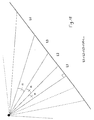
- the distribution of increasing or decreasing mesh sizes over the portions of each intermediate section between each mesh of minimum size and the central portion is obtained for example by determining the points of intersection with each section of pipe, a bundle of straight lines competing at a point and forming a constant angle between them.
- the method according to the invention preferably includes a simplification prior to the pipe topography so that the total number of meshes of the pipe mesh allow realistic modeling of the physics of phenomena in a fixed time.
- the method comprises a representation of the pipe in the form of a graph connecting the curvilinear abscissa and the level variation, and a simplification of the number of sections a) by affecting at each point between two successive sections a weight taking into account the length of the sections and their respective slopes, b) by selecting from the points arranged in ascending or descending weight order, those with the most weight high, the simplified topography being that of the graph passing through the points selected.
- the selection of the most weighted pipe points is obtained for example by locating in the arrangement of points a discontinuity of weight greater than a certain fixed threshold.
- the method includes a representation of the pipe in the form of a graph connecting the curvilinear abscissa and the level variation, and a simplification of the number of sections by a) the formation of the frequency spectrum of the curve representative of the topography of the driving, b) the attenuation of the highest frequencies of the spectrum translating the most small variations in topography and c) reconstruction of a simplified topography corresponding to the rectified frequency spectrum.
- the selection is made for example by a) a sampling of the curve representative of the topography of the pipe with a chosen sampling pitch so that the smallest section of the pipe contains at least two steps b) a determination of the frequency spectrum of the curve sampled by application, c) spectrum correction by low-pass filtering whose cutoff frequency is chosen according to a number of meshes maximum fixed to subdivide the pipe, and, d) a determination of the topography corresponding to the rectified frequency spectrum.
- the two previous automatic simplification modes can be applied independently of one another or else successively, the second mode being applied preferably when the first mode does not allow for simplification notable of the topography.
- the method according to the invention allows, by purely mathematical criteria, automatic identification of the configuration of a pipe, based on a spectral analysis of the curve representative of profile variations.
- a spectral analysis of the curve representative of profile variations we are looking for one that makes it possible to distinguish the portions of the profile to simplify and important profile portions.
- Weight The 1 .
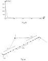
- the spectrum (Curvilinear abscissa - Weight) presents in the majority of cases, a succession of peaks of all sizes. These spectra such as that of Fig. 4 cannot generally be analyzed directly. Under these conditions, the technique used here consists in classifying the weights (P) in ascending or descending order and in assigning to them each the corresponding classification index (CI) by weight from 1 to N.
- CI classification index
- log Weight-Index which brings out the orders of magnitude better because a jump of n on such a spectrum means a ratio of 10 n on the weights. All the weights having the same order of magnitude are classified on more or less horizontal bearings. Two weights of different orders of magnitude will be separated by a vertical line segment. This leads to a cascading spectrum, making it possible to easily read the different orders of magnitude present in the topography.
- the logarithmic spectrum Log P contains two very distinct steps separated by a vertical segment.
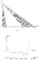
- topography in Fig. 6 there are three parts distinct. It begins with a 3 km riser, followed by a horizontal part sawtooth over 20 km which ends with another 200m riser also in Sawtooth. Its spectrum is that of Fig. 5.
- the first triplet which obeys the criterion threshold is formed by points 4, 5 and 6.
- the simplification threshold is point index 6.
- a jump greater than 2 in the logarithmic scale separates the landings horizontal on either side of points 5 and 6. This ensures that the points to left of index 5 have weights at least 100 times greater than those found to the right of index 6.
- the first simplification mode which has just been described is easy to implement. work and based on relatively simple algorithms executable quickly. he is suitable for topographies with several orders of magnitude, such as previous topography which could have been considerably simplified because it contained points having negligible weights compared to others.
- FFT Fast Fourier Transform
- the simplest method of filtering is, for example, to apply a threshold, all Fourier coefficients (FC) whose amplitude A (FC) is less than this threshold being eliminated (coefficients less than 40 for example on the example of the Fig.9. Only the information contained in frequencies below this threshold is retained. We reconstitute by reverse transform the simplified typography corresponding.
- the principle of the mesh will consist in independently meshing the sections of conduct between two imposed edges.
- the mesh is refined at the points of the topography likely to see build up of liquid or gas. This is why, we are going to arrange to place a short stitch before and after each elbow and larger between the elbows. On the other hand, it is not useful to finely mesh the intermediate parts of the sections between the elbows.
- the size of the meshes after the one following a bend gradually increases over a third of the length of the section, remains constant over the next third to finally decrease gradually over the last third before the final short stitch as shown in Fig. 10.
- Parameter P makes it possible to reduce the difference between the minimum lengths and maximum so as to gradually make the mesh homogeneous for large numbers of meshes.
- This parameter is defined for example as follows. For a number of meshes requested less than or equal to 60 for example, we set it for example to 60. This is the default mesh. The parameter is worth 40. The smallest mesh will be worth L / 100 and the larger L / 20. The total number of meshes will be between 20 and 100.
- a number of meshes greater than or equal to 150 means that the modeling to be treated is certainly more delicate.
- the goal is then to build a homogeneous mesh. For this, the minimum and maximum sizes must be close to each other. We will therefore set the parameter at 10.
- the total number of meshes will then be between L / N +10 and L / N -10.
- This parameter being determined, it is possible to isolate the edges imposed by short cells and to discretize the midpoints of the sections by cells long.
- N E ( ⁇ / ⁇ ).
- the principle used to carry out the insertion of the edges of meshes is at the same time simple and flexible. It allows, through a single parameter, to create a mesh either uniform or heterogeneous, refined in important places.
Landscapes
- Engineering & Computer Science (AREA)
- Mechanical Engineering (AREA)
- General Engineering & Computer Science (AREA)
- Management, Administration, Business Operations System, And Electronic Commerce (AREA)
- Complex Calculations (AREA)
Abstract
Description
- 1 - Assurer la convergence du calcul ;
- 2 - Représenter au mieux les accumulations importantes de liquide dans les points bas de la conduite ;
- 3 - Placer les équipements sur un bord de maille ;
- 4 - Imposer à deux mailles consécutives d'avoir le même ordre de longueur ;
- 5 - Respecter la longueur totale de la conduite ;
- 6 - Limiter le nombre de mailles au minimum possible en respectant les contraintes précédentes, pour ne pas trop pénaliser la simulation avec le temps de calcul.
- -la Fig.1 montre deux modes de représentation schématique de la variation de l'élévation (E) d'une conduite en fonction de l'abscisse (A) selon que c'est une abscisse cartésienne (ca) ou curviligne (cu);
- les Fig.2a, 2b montrent respectivement la topographie schématique d'une conduite en forme de W en coordonnées curvilignes, et une partie agrandie de cette même topographie, discrétisée par un maillage approprié ;
- la Fig. 3 montre un mode d'attribution de poids (P) à des points de la topographie d'une conduite ;
- la Fig. 4 montre un exemple de spectre adimensionnel (PA) de poids en fonction de la longueur (L);
- la Fig. 5 montre un exemple d'arrangement des points par paliers de poids décroissants, permettant de repérer la position d'un seuil et de simplifier la topographie de la conduite ;
- la Fig. 6 montre un exemple de topographie d'une conduite marine (variation de l'élévation E en fonction de l'abscisse curviligne ca) comportant un « riser» à ses extrémités ;
- la Fig. 7 montre la topographie simplifiée de la même conduite, que l'on obtient par sélection des poids ;
- la Fig. 8 montre que, sans les « risers » terminaux, la forme générale de la même conduite est plus difficile à dégager ;
- la Fig.9 montre un spectre de fréquence typique d'une conduite ;
- la Fig. 10 montre un exemple de tronçon de conduite avec une distribution de mailles de différentes tailles, les plus petites M1 étant positionnées aux coudes, les plus grandes, M2 étant placées dans le tiers central, les mailles intermédiaires M3 étant interposées et résultant d'une interpolation I entre les unes et les autres ;
- la Fig. 11 montre un mode de formation de mailles de tailles croissantes ;
- la Fig. 12 illustre le mode de découpage angulaire d'une portion intermédiaire sur un tronçon de conduite ; et
- la Fig.13 montre le maillage obtenu par la mise en oeuvre de la méthode, sur une conduite sous-marine de 90km de longueur.
- la taille d'une maille se déduise de celle de la précédente en la multipliant par un facteur f.
- la somme des n longueurs ainsi créées soit égale à (L1+L2)
- la taille de la dernière cellule puisse s'exprimer sous la forme fn +1.L 1 f.
Claims (8)
- Méthode de maillage automatique de conduites permettant l'implémentation de codes de modélisation de fluides acheminés par ces conduites, caractérisée en ce que, ayant défini une taille minimale de maille et une taille maximale de maille, on subdivise la conduite en tronçons délimités par des coudes, on positionne une maille de taille minimale de part et d'autre de chaque coude, on positionne des grandes mailles de taille au plus égale à la taille maximale dans la portion centrale de chaque tronçon, et on répartit des mailles de tailles croissantes ou décroissantes sur les portions intermédiaires de chaque tronçon entre chaque maille de taille minimale et la portion centrale.
- Méthode selon la revendication 1, caractérisée en ce que l'on répartit des mailles de tailles croissantes ou décroissantes sur les portions de chaque tronçon intermédiaire entre chaque maille de taille minimale et la portion centrale en déterminant les points d'intersection avec chaque tronçon de conduite, d'un faisceau de droites concourant en un point et formant entre elles un angle constant.
- Méthode selon la revendication 1, caractérisée en ce que l'on détermine la position du sommet du faisceau de droites sur un axe passant par un coude de la conduite et perpendiculaire à chaque tronçon, à une distance (y) de celui-ci qui est fonction de la taille (L1, L3) des mailles extrêmes de chaque portion intermédiaire et de leur écart (L2).
- Méthode de maillage selon l'une des revendications 1 à 3, caractérisée en ce qu'elle comporte une simplification préalable de la topographie de la conduite.
- Méthode de maillage selon la revendication 4, caractérisée en ce qu'elle comporte une représentation de la conduite sous la forme d'un graphe reliant l'abscisse curviligne et la variation de niveau, et une simplification du nombre de tronçons en affectant à chaque point entre deux tronçons successifs un poids prenant en compte la longueur (L1, L2) des tronçons et leurs pentes respectives (P1, P2) et en sélectionnant parmi les points rangés par ordre de poids croissant ou décroissant, ceux dont le poids est le plus élevé.
- Méthode de maillage selon la revendication 5, caractérisée en ce l'on sélectionne les points de la conduite dont le poids est le plus élevé en repérant dans le rangement de points une discontinuité de poids supérieure à un certain seuil fixé (ΔP).
- Méthode de maillage selon la revendication 5, caractérisée en ce qu'elle comporte une représentation de la conduite sous la forme d'un graphe reliant l'abscisse curviligne et la variation de niveau, et une simplification du nombre de tronçons par la formation du spectre de fréquence de la courbe représentative de la topographie de la conduite, l'atténuation des plus hautes fréquences du spectre traduisant les plus petites variations de topographie et la reconstruction d'une topographie simplifiée correspondant au spectre de fréquence rectifié.
- Méthode de maillage selon la revendication 7, caractérisée en ce qu'elle comporte un échantillonnage de la courbe représentative de la topographie de la conduite avec un pas d'échantillonnage choisi pour que le plus petit tronçon de la conduite contienne au moins deux pas d'échantillonnage, une détermination du spectre de fréquence de la courbe échantillonnée par application, une correction du spectre par filtrage passe-bas dont la fréquence de coupure est choisie en fonction d'un nombre de mailles maximal fixé pour subdiviser la conduite, et la détermination de la topographie correspondant au spectre de fréquence rectifié.
Applications Claiming Priority (2)
| Application Number | Priority Date | Filing Date | Title |
|---|---|---|---|
| FR0008200A FR2810721B1 (fr) | 2000-06-23 | 2000-06-23 | Methode de maillage automatique de conduites permettant l'implementation de codes de modelisation de flux |
| FR0008200 | 2000-06-23 |
Publications (1)
| Publication Number | Publication Date |
|---|---|
| EP1167865A1 true EP1167865A1 (fr) | 2002-01-02 |
Family
ID=8851703
Family Applications (1)
| Application Number | Title | Priority Date | Filing Date |
|---|---|---|---|
| EP01401422A Withdrawn EP1167865A1 (fr) | 2000-06-23 | 2001-05-31 | Méthode de maillage automatique de conduites permettant l'implémentation de codes de modélisation de flux |
Country Status (5)
| Country | Link |
|---|---|
| US (1) | US6952663B2 (fr) |
| EP (1) | EP1167865A1 (fr) |
| CA (1) | CA2351113A1 (fr) |
| FR (1) | FR2810721B1 (fr) |
| NO (1) | NO20013125L (fr) |
Families Citing this family (1)
| Publication number | Priority date | Publication date | Assignee | Title |
|---|---|---|---|---|
| US20070078637A1 (en) * | 2005-09-30 | 2007-04-05 | Berwanger, Inc. | Method of analyzing oil and gas production project |
Citations (5)
| Publication number | Priority date | Publication date | Assignee | Title |
|---|---|---|---|---|
| US5274643A (en) * | 1992-12-11 | 1993-12-28 | Stratacom, Inc. | Method for optimizing a network having virtual circuit routing over virtual paths |
| EP0626652A1 (fr) * | 1993-05-11 | 1994-11-30 | Tokyo Gas Company Limited | Procédé et appareil pour la détermination des circuits élémentaires et des valeurs de flux initiales dans un réseau de conduites |
| US5550761A (en) | 1994-02-08 | 1996-08-27 | Institut Francais Du Petrole | Method for modelling multiphase flows in pipelines |
| FR2756045A1 (fr) | 1996-11-18 | 1998-05-22 | Inst Francais Du Petrole | Methode pour former un modele de simulation d'ecoulements diphasiques transitoires dans des conduites d'acheminement |
| FR2756044A1 (fr) | 1996-11-18 | 1998-05-22 | Inst Francais Du Petrole | Methode pour constituer un modele representatif d'ecoulements polyphasiques dans des conduites de production petroliere |
Family Cites Families (2)
| Publication number | Priority date | Publication date | Assignee | Title |
|---|---|---|---|---|
| JP3162006B2 (ja) * | 1997-11-10 | 2001-04-25 | 核燃料サイクル開発機構 | 抽出系のシミュレーション方法 |
| JP3440844B2 (ja) * | 1998-10-07 | 2003-08-25 | 三菱電機株式会社 | 二相流熱流動解析方法およびその装置 |
-
2000
- 2000-06-23 FR FR0008200A patent/FR2810721B1/fr not_active Expired - Fee Related
-
2001
- 2001-05-31 EP EP01401422A patent/EP1167865A1/fr not_active Withdrawn
- 2001-06-18 CA CA002351113A patent/CA2351113A1/fr not_active Abandoned
- 2001-06-19 US US09/883,402 patent/US6952663B2/en not_active Expired - Fee Related
- 2001-06-22 NO NO20013125A patent/NO20013125L/no not_active Application Discontinuation
Patent Citations (6)
| Publication number | Priority date | Publication date | Assignee | Title |
|---|---|---|---|---|
| US5274643A (en) * | 1992-12-11 | 1993-12-28 | Stratacom, Inc. | Method for optimizing a network having virtual circuit routing over virtual paths |
| EP0626652A1 (fr) * | 1993-05-11 | 1994-11-30 | Tokyo Gas Company Limited | Procédé et appareil pour la détermination des circuits élémentaires et des valeurs de flux initiales dans un réseau de conduites |
| US5550761A (en) | 1994-02-08 | 1996-08-27 | Institut Francais Du Petrole | Method for modelling multiphase flows in pipelines |
| FR2756045A1 (fr) | 1996-11-18 | 1998-05-22 | Inst Francais Du Petrole | Methode pour former un modele de simulation d'ecoulements diphasiques transitoires dans des conduites d'acheminement |
| FR2756044A1 (fr) | 1996-11-18 | 1998-05-22 | Inst Francais Du Petrole | Methode pour constituer un modele representatif d'ecoulements polyphasiques dans des conduites de production petroliere |
| US5960187A (en) | 1996-11-18 | 1999-09-28 | Institut Francais Du Petrole | Method for forming a simulation model of transient two-phase flows in pipelines |
Also Published As
| Publication number | Publication date |
|---|---|
| CA2351113A1 (fr) | 2001-12-23 |
| NO20013125D0 (no) | 2001-06-22 |
| US6952663B2 (en) | 2005-10-04 |
| US20020046013A1 (en) | 2002-04-18 |
| FR2810721B1 (fr) | 2002-09-20 |
| FR2810721A1 (fr) | 2001-12-28 |
| NO20013125L (no) | 2001-12-24 |
Similar Documents
| Publication | Publication Date | Title |
|---|---|---|
| FR2735571A1 (fr) | Debitmetre a venturi pour mesure dans une veine d'ecoulement d'un fluide | |
| EP1176481B1 (fr) | Methode et système pour estimer en temps réel le mode d'écoulement d'une veine fluide polyphasique, en tous points d'une conduite | |
| CA2175617C (fr) | Filtre de modification ou d'amelioration de la parole et appareils, systemes et methode utilisant ce filtre | |
| EP4047492A1 (fr) | Ré-échantillonnage par interpolation d'un signal audio pour un codage /décodage à bas retard | |
| FR2851670A1 (fr) | Methode pour elaborer plus rapidement un modele stochastique representatif d'un reservoir heterogene souterrain, contraint par des donnees statiques et dynamiques incertaines | |
| FR2900753A1 (fr) | Procede d'optimisation automatique d'un reseau de transport de gaz naturel | |
| EP1741047B1 (fr) | Procédé de recherche de contenu, notamment d'extraits communs entre deux fichiers informatiques | |
| WO2004063983A2 (fr) | Methode pour modeliser des caracteristiques hydrodynamiques d'ecoulements polyphasiques par reseaux de neurones | |
| FR3097968A1 (fr) | Procédé de mesure de la vitesse d’un fluide | |
| EP2232489B1 (fr) | Codage/decodage par transformee, a fenetres adaptatives | |
| WO2011012793A1 (fr) | Procède de prévision d'un bruit de roulement d'un pneumatique | |
| CA2019417C (fr) | Procede d'optimisation de tubes multi-couches en materiaux composites et tubes obtenus par le procede | |
| CA2351113A1 (fr) | Methode de maillage automatique de conduites permettant l'implementation de codes de modelisation de flux | |
| FR2843893A1 (fr) | Methode pour optimiser le fonctionnement d'une unite de separation de xylenes par contre courant simule | |
| EP1746521A1 (fr) | Procédé de classement d'un ensemble de documents électroniques du type pouvant contenir des liens hypertextes vers d'autres documents électroniques | |
| EP3356780B1 (fr) | Procede de detection de fuite dans un reseau de fluide | |
| EP0714030B1 (fr) | Simulateur d'impulsion électromagnétique | |
| BE1013153A3 (fr) | Procede et systeme de prelevement d'information. | |
| FR2691544A1 (fr) | Dispositif de cotation d'un lubrifiant, notamment de moteur de véhicule automobile. | |
| EP2667208A1 (fr) | Système électronique à capteurs intégrés, procédé d'estimation de valeur de grandeur physique de fonctionnement et programme d'ordinateur correspondant | |
| Coquet | La derive dans l’évaluation de l’incertitude | |
| CN108595387A (zh) | 一种自适应的idw插值方法 | |
| FR3142270A1 (fr) | Procédé de détermination d’un réseau de tubes dans un espace de référence d’un véhicule automobile | |
| Pentecôte et al. | Les conséquences de la crise financiere sur le commerce intra-européen | |
| EP2630446B1 (fr) | Système et procédé de cartographie avec représentation appariée continue |
Legal Events
| Date | Code | Title | Description |
|---|---|---|---|
| PUAI | Public reference made under article 153(3) epc to a published international application that has entered the european phase |
Free format text: ORIGINAL CODE: 0009012 |
|
| AK | Designated contracting states |
Kind code of ref document: A1 Designated state(s): AT BE CH CY DE DK ES FI FR GB GR IE IT LI LU MC NL PT SE TR Kind code of ref document: A1 Designated state(s): GB IT SE |
|
| AX | Request for extension of the european patent |
Free format text: AL;LT;LV;MK;RO;SI |
|
| 17P | Request for examination filed |
Effective date: 20020702 |
|
| AKX | Designation fees paid |
Free format text: GB IT SE |
|
| REG | Reference to a national code |
Ref country code: DE Ref legal event code: 8566 |
|
| 17Q | First examination report despatched |
Effective date: 20071217 |
|
| STAA | Information on the status of an ep patent application or granted ep patent |
Free format text: STATUS: THE APPLICATION IS DEEMED TO BE WITHDRAWN |
|
| 18D | Application deemed to be withdrawn |
Effective date: 20121201 |