EP1167639B1 - Device to control the dynamic stability of an industrial vehicle - Google Patents
Device to control the dynamic stability of an industrial vehicle Download PDFInfo
- Publication number
- EP1167639B1 EP1167639B1 EP01202450A EP01202450A EP1167639B1 EP 1167639 B1 EP1167639 B1 EP 1167639B1 EP 01202450 A EP01202450 A EP 01202450A EP 01202450 A EP01202450 A EP 01202450A EP 1167639 B1 EP1167639 B1 EP 1167639B1
- Authority
- EP
- European Patent Office
- Prior art keywords
- vehicle
- stability
- industrial vehicle
- control
- industrial
- Prior art date
- Legal status (The legal status is an assumption and is not a legal conclusion. Google has not performed a legal analysis and makes no representation as to the accuracy of the status listed.)
- Expired - Lifetime
Links
Images


Classifications
-
- B—PERFORMING OPERATIONS; TRANSPORTING
- B66—HOISTING; LIFTING; HAULING
- B66F—HOISTING, LIFTING, HAULING OR PUSHING, NOT OTHERWISE PROVIDED FOR, e.g. DEVICES WHICH APPLY A LIFTING OR PUSHING FORCE DIRECTLY TO THE SURFACE OF A LOAD
- B66F9/00—Devices for lifting or lowering bulky or heavy goods for loading or unloading purposes
- B66F9/06—Devices for lifting or lowering bulky or heavy goods for loading or unloading purposes movable, with their loads, on wheels or the like, e.g. fork-lift trucks
- B66F9/075—Constructional features or details
- B66F9/07586—Suspension or mounting of wheels on chassis
-
- B—PERFORMING OPERATIONS; TRANSPORTING
- B60—VEHICLES IN GENERAL
- B60G—VEHICLE SUSPENSION ARRANGEMENTS
- B60G17/00—Resilient suspensions having means for adjusting the spring or vibration-damper characteristics, for regulating the distance between a supporting surface and a sprung part of vehicle or for locking suspension during use to meet varying vehicular or surface conditions, e.g. due to speed or load
- B60G17/015—Resilient suspensions having means for adjusting the spring or vibration-damper characteristics, for regulating the distance between a supporting surface and a sprung part of vehicle or for locking suspension during use to meet varying vehicular or surface conditions, e.g. due to speed or load the regulating means comprising electric or electronic elements
-
- B—PERFORMING OPERATIONS; TRANSPORTING
- B60—VEHICLES IN GENERAL
- B60G—VEHICLE SUSPENSION ARRANGEMENTS
- B60G9/00—Resilient suspensions of a rigid axle or axle housing for two or more wheels
- B60G9/02—Resilient suspensions of a rigid axle or axle housing for two or more wheels the axle or housing being pivotally mounted on the vehicle, e.g. the pivotal axis being parallel to the longitudinal axis of the vehicle
-
- B—PERFORMING OPERATIONS; TRANSPORTING
- B62—LAND VEHICLES FOR TRAVELLING OTHERWISE THAN ON RAILS
- B62D—MOTOR VEHICLES; TRAILERS
- B62D49/00—Tractors
- B62D49/08—Tractors having means for preventing overturning or tipping
-
- B—PERFORMING OPERATIONS; TRANSPORTING
- B66—HOISTING; LIFTING; HAULING
- B66C—CRANES; LOAD-ENGAGING ELEMENTS OR DEVICES FOR CRANES, CAPSTANS, WINCHES, OR TACKLES
- B66C23/00—Cranes comprising essentially a beam, boom, or triangular structure acting as a cantilever and mounted for translatory of swinging movements in vertical or horizontal planes or a combination of such movements, e.g. jib-cranes, derricks, tower cranes
- B66C23/88—Safety gear
- B66C23/90—Devices for indicating or limiting lifting moment
- B66C23/905—Devices for indicating or limiting lifting moment electrical
-
- B—PERFORMING OPERATIONS; TRANSPORTING
- B66—HOISTING; LIFTING; HAULING
- B66F—HOISTING, LIFTING, HAULING OR PUSHING, NOT OTHERWISE PROVIDED FOR, e.g. DEVICES WHICH APPLY A LIFTING OR PUSHING FORCE DIRECTLY TO THE SURFACE OF A LOAD
- B66F17/00—Safety devices, e.g. for limiting or indicating lifting force
- B66F17/003—Safety devices, e.g. for limiting or indicating lifting force for fork-lift trucks
-
- E—FIXED CONSTRUCTIONS
- E02—HYDRAULIC ENGINEERING; FOUNDATIONS; SOIL SHIFTING
- E02F—DREDGING; SOIL-SHIFTING
- E02F9/00—Component parts of dredgers or soil-shifting machines, not restricted to one of the kinds covered by groups E02F3/00 - E02F7/00
- E02F9/20—Drives; Control devices
- E02F9/22—Hydraulic or pneumatic drives
- E02F9/2257—Vehicle levelling or suspension systems
-
- E—FIXED CONSTRUCTIONS
- E02—HYDRAULIC ENGINEERING; FOUNDATIONS; SOIL SHIFTING
- E02F—DREDGING; SOIL-SHIFTING
- E02F9/00—Component parts of dredgers or soil-shifting machines, not restricted to one of the kinds covered by groups E02F3/00 - E02F7/00
- E02F9/24—Safety devices, e.g. for preventing overload
-
- B—PERFORMING OPERATIONS; TRANSPORTING
- B60—VEHICLES IN GENERAL
- B60G—VEHICLE SUSPENSION ARRANGEMENTS
- B60G2200/00—Indexing codes relating to suspension types
- B60G2200/30—Rigid axle suspensions
- B60G2200/32—Rigid axle suspensions pivoted
-
- B—PERFORMING OPERATIONS; TRANSPORTING
- B60—VEHICLES IN GENERAL
- B60G—VEHICLE SUSPENSION ARRANGEMENTS
- B60G2400/00—Indexing codes relating to detected, measured or calculated conditions or factors
- B60G2400/50—Pressure
- B60G2400/51—Pressure in suspension unit
Definitions
- the present invention relates to a device to control the dynamic stability of an industrial vehicle.
- the device according to the present invention is appropriate to be fitted on an industrial vehicle such as lift trucks with telescoping boom, bucket loaders or back-hoe loaders, crane trucks, tractors and similar.
- the casing or chassis of the vehicle is subjected to a plurality of external loads which can be schematised as forces and moments of forces that tend to influence the stability of the vehicle.
- Measurement of external physical sizes is useful to determine the conditions of operation and stability of the vehicle; for example, it is possible to measure the vertical forces and overturning moments in the various directions of the space to calculate the stability of industrial vehicles with axles with suspensions, during the various manoeuvres of turning, braking, acceleration or lifting the load, in order to calculate the induced forces and the moments of destabilisation of the vehicle.
- Document US 5,627,751 discloses a land vehicle comprising a suspension controller which receives input signals generated from a plurality of sensors, on the basis of which it controls the suspension of the vehicle through the activation of a plurality of servo-valves.
- the suspension controller described in document US 5,627,751 further comprises failure detection means for detecting the failure of a sensor and, in case of failure, for replacing the signal of the failed sensor with a replacement signal calculated on the basis of measured or calculated data stored in a memory device.
- Document US 5,475,593 describes a vehicle comprising a central control device connected to a plurality of corner control devices each of which activates a servo-valve for controlling an actuator connected between the vehicle body and the wheel assembly inter alia on the basis of signals generated from a force transducer.
- the object of the present invention is, therefore, to produce a device for controlling the dynamic stability of an industrial vehicle which operates in an active and integrated mode in the vehicle, during its normal use, to guarantee the best conditions of stability and self-levelling of this vehicle.
- Another object of the present invention is to produce a device for control of the dynamic stability of an industrial vehicle, which can be installed simply and which may allow an operator sitting in the cab to be informed of all conditions in the vicinity of the limit of stability in which the vehicle finds itself operating.
- Yet another object of the present invention is to present a device for control of the dynamic stability of an industrial vehicle which considerably increases the reliability and overall comfort of the vehicle to which it is fitted, reducing stresses to which the chassis of the vehicle might be subjected.
- an industrial vehicle comprising a device for control of the dynamic stability of the vehicle, as claimed in claim 1, which is referred to for brevity.
- each axle 10', 10 " comprises a central casing 11 from which suspension arms 12 and 13 and 12' and 13' extend.
- each of the suspension arms 12, 13, 12' and 13' are articulated steering pivots 14, 15, 14', 15' of the wheels; said wheels are not shown for simplicity.
- the central casing 11 also supports a steering actuator, capable of making its rod slide axially.
- hydraulic cylinders 17, 17' and 18, 18' interposed between the axles 10',10" and the chassis 16 of the industrial vehicle.
- the hydraulic cylinders 17, 17' and 18, 18' are connected to hinges 19, 20 integral with the chassis 16.
- the rods of the hydraulic cylinders 17, 17' and 18, 18' are instead connected to hinges 21, 22, 21' and 22' integral with the suspension arms 12 and 13 and 12' and 13' of the axles 10', 10".
- the hydraulic cylinders 17, 17' and 18, 18' are fed by an electronically controlled hydraulic control unit.
- Each of the hydraulic cylinders L7, 17' and 18, 18' is controlled by the device for control of the dynamic stability of an industrial vehicle, according to the present invention, the block diagram of which is shown globally with the numeric reference 30 in figure 4 .
- the device 30 is firstly provided with pressure transducers 31, 32, 33 and 34, each of which is associated with a respective hydraulic cylinders 17, 17' and 18, 18'.
- Each of the pressure transducers 31, 32, 33 and 34 transmits a signal to a respective amplifier 35, 36, 37 and 38 and these amplified signals are sent to a control unit 39.
- the control unit 39 also receives, from a block 40, data relevant to the specific vehicle to which the device 30 is applied; in fact, the block 40 can memorize or receive data such as type of vehicle, weight, significant dimensions such as track, wheel base, length and significant angles of any lifting booms of crane trucks and/or similar vehicles, etc., all through an intelligent self-learning system which activates itself after installation of the device for stability of the vehicle coming off the assembly line.
- control unit 39 Taking account of the information received from the pressure transducers 31, 32, 33 and 34 together with the information received from the block 40, the control unit 39 processes a signal relevant to the condition of stability of the vehicle, all in real time.
- This signal of the control unit 39 is further processed by a block 41 which transmits it to an appropriate logic-hydraulic system incorporating appropriate hydraulic valves to control the flow towards a plurality of actuation pipes 42, 43, 44 and 45, each of which is associated with one of the hydraulic cylinders 17, 17' and 18, 18'.
- the electronic circuit schematised in figure 4 by means of appropriate control software, processes data received from each pressure sensor 31, 32, 33, and 34, appropriately amplified, so as to calculate the stability of the vehicle in real time and take appropriate measures to dynamically balance the aforesaid vehicle, acting through the actuation pipes 42, 43, 44 and 45 independently on the hydraulic cylinders 17, 17' and 18, 18'.
- each hydraulic cylinder 17, 17' and 18, 18' can be regulated by means of an appropriate logic-hydraulic system incorporating appropriate hydraulic valves to control flow.
- the device 30 also takes account of other important variables such as the extension of the boom of the crane and any downward inclination of the forks fitted to the end of this boom, as the load to be lifted is applied to the aforesaid ends and/or forks.
- the system recognises the overturning moment, as a consequence recognising the decrease in the load on the axles, in particular on the rear axle, after having appropriately processed the data supplied for the purpose of stability.
- the device according to the invention is capable of recognising the limit condition of lateral stability: the signal transmitted by the software could therefore disable vehicle starting, acting on the transmission to prevent motion.
- the device 30 with an acoustic and/or visual warning device which indicates the possibility of limit condition of vehicle stability to the vehicle operator.
- the presence of the device described allows high reliability of the vehicle, simultaneously increasing the comfort of use.
- vehicles equipped with the device according to the invention are safer and easier to drive than those not fitted with the device.
- the device allows the vehicle to which it is fitted to be transformed into a dynamic system permitting prevention of dangerous limit conditions that would lead to instability of the vehicle.
- the device can be fitted to any type of axle with suspension, for example, also to axles without a Panhard rod, that is with different suspension geometries than those indicated herein.
- the system of the invention thus allows active control to be obtained, especially with self-stabilisation of the vehicle, which is extremely interesting when moving at relatively high speeds off road, especially with a load at a considerable height from the ground.
- the shock absorbing effect of the suspensions is deactivated, the axle thus acting as if it was connected rigidly to a component of the articulated quadrilateral identified between the chassis of the vehicle, the suspension cylinders, the axle and the Panhard rod, as in annexed figure 3 .
Landscapes
- Engineering & Computer Science (AREA)
- Mechanical Engineering (AREA)
- Structural Engineering (AREA)
- Transportation (AREA)
- Civil Engineering (AREA)
- General Engineering & Computer Science (AREA)
- Mining & Mineral Resources (AREA)
- Life Sciences & Earth Sciences (AREA)
- Geology (AREA)
- Chemical & Material Sciences (AREA)
- Combustion & Propulsion (AREA)
- Vehicle Body Suspensions (AREA)
- Fluid-Damping Devices (AREA)
- Forklifts And Lifting Vehicles (AREA)
Abstract
Description
- The present invention relates to a device to control the dynamic stability of an industrial vehicle.
- More specifically, the device according to the present invention is appropriate to be fitted on an industrial vehicle such as lift trucks with telescoping boom, bucket loaders or back-hoe loaders, crane trucks, tractors and similar.
- As is known, during operations to manoeuvre or work with these industrial vehicles, the casing or chassis of the vehicle is subjected to a plurality of external loads which can be schematised as forces and moments of forces that tend to influence the stability of the vehicle.
- This is accentuated by these phenomena occurring with the vehicle fully loaded and/or on uneven ground.
- In fact, during operations to manoeuvre an industrial vehicle with suspensions, the entire casing or chassis of the vehicle is subjected to various stresses determined by a series of forces and overturning moments that are produced both due to movement of the load or due to variations in the stability of the vehicle in motion on the ground, all of which may occur in static, almost-static or dynamic conditions.
- Measurement of external physical sizes is useful to determine the conditions of operation and stability of the vehicle; for example, it is possible to measure the vertical forces and overturning moments in the various directions of the space to calculate the stability of industrial vehicles with axles with suspensions, during the various manoeuvres of turning, braking, acceleration or lifting the load, in order to calculate the induced forces and the moments of destabilisation of the vehicle.
- Currently, the operation to measure these forces and moments can be performed using specifically designed measurement instruments, only by simulation to be performed in the laboratory.
- Moreover, to date, the various physical sizes of interest are measured approximately and placed in relation to one another by means of force transducers, which are fixed only externally to the casing of the axle or the chassis of the vehicle, thus influenced by all possible effects of disturbance or drift of the signal to be measured, which can be influenced by the effects of temperature, deflections of the structural components of the axle, operating pressures of the brakes, making the final information inaccurate and unreliable.
- Therefore, fitting these transducers in specific positions of each rotating axle does not permit accurate measurements, as they are influenced by many external factors, in addition to those intrinsic to the geometry of the axle or the coupling of the axle with the vehicle chassis.
- Lastly, all this requires the development of complex transformation algorithms, appropriate to translate the position through time of each vehicle axle into the fixed coordinates system of the vehicle.
- Document
US 5,627,751 discloses a land vehicle comprising a suspension controller which receives input signals generated from a plurality of sensors, on the basis of which it controls the suspension of the vehicle through the activation of a plurality of servo-valves. The suspension controller described in documentUS 5,627,751 further comprises failure detection means for detecting the failure of a sensor and, in case of failure, for replacing the signal of the failed sensor with a replacement signal calculated on the basis of measured or calculated data stored in a memory device. - Document
US 5,475,593 describes a vehicle comprising a central control device connected to a plurality of corner control devices each of which activates a servo-valve for controlling an actuator connected between the vehicle body and the wheel assembly inter alia on the basis of signals generated from a force transducer. - The object of the present invention is, therefore, to produce a device for controlling the dynamic stability of an industrial vehicle which operates in an active and integrated mode in the vehicle, during its normal use, to guarantee the best conditions of stability and self-levelling of this vehicle.
- Another object of the present invention is to produce a device for control of the dynamic stability of an industrial vehicle, which can be installed simply and which may allow an operator sitting in the cab to be informed of all conditions in the vicinity of the limit of stability in which the vehicle finds itself operating.
- Yet another object of the present invention is to present a device for control of the dynamic stability of an industrial vehicle which considerably increases the reliability and overall comfort of the vehicle to which it is fitted, reducing stresses to which the chassis of the vehicle might be subjected.
- These and other objects are attained by an industrial vehicle comprising a device for control of the dynamic stability of the vehicle, as claimed in claim 1, which is referred to for brevity.
- Further characteristics of the present invention are also defined in the subsequent claims.
- Further objects and advantages of the present invention shall become clearer from the description below and the annexed drawings, provided merely as an exemplary and non-limiting example, in which:
-
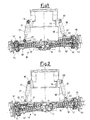
figure 1 shows a front view of a pair of axles, fitted on a generic chassis of an industrial vehicle, incorporating the device for control of the dynamic stability, according to the present invention, said axles being positioned mutually in a first operating position; -
figure 2 shows a front view of the pair of axles infigure 1 , in a second mutual operating position; -
figure 3 shows a view, in a part section according to a plan perpendicular to the axis of one of the axles, of an assembly comprising part of the axle and a hydraulic cylinder, which sends pressure to a transducer positioned therein to electronically read the pressure measurement (on each wheel hub respectively) in order to process data required to establish conditions of dynamic stability of an industrial vehicle, according to the present invention; and -
figure 4 shows a block diagram showing the operating logic of the device for control of the dynamic stability of an industrial vehicle, according to the present invention. - With specific reference firstly to
figure 1-2 , the axle assembly is indicated globally with thenumeric reference 10, and infigures 1-2 it can be seen that eachaxle 10', 10 " comprises acentral casing 11 from whichsuspension arms - At the end of each of the
suspension arms steering pivots - The
central casing 11 also supports a steering actuator, capable of making its rod slide axially. - Moreover, interposed between the
axles 10',10" and thechassis 16 of the industrial vehicle arehydraulic cylinders - The
hydraulic cylinders hinges chassis 16. - The rods of the
hydraulic cylinders hinges suspension arms axles 10', 10". - The
hydraulic cylinders - No further detailed description of the structure of the pair of axles and their assembly on the chassis of an industrial vehicle is given herein and, therefore, only the functional elements useful to interpret and actuate the invention are referred to.
- Each of the hydraulic cylinders L7, 17' and 18, 18' is controlled by the device for control of the dynamic stability of an industrial vehicle, according to the present invention, the block diagram of which is shown globally with the
numeric reference 30 infigure 4 . - The
device 30 is firstly provided withpressure transducers hydraulic cylinders - Each of the
pressure transducers respective amplifier control unit 39. - The
control unit 39 also receives, from ablock 40, data relevant to the specific vehicle to which thedevice 30 is applied; in fact, theblock 40 can memorize or receive data such as type of vehicle, weight, significant dimensions such as track, wheel base, length and significant angles of any lifting booms of crane trucks and/or similar vehicles, etc., all through an intelligent self-learning system which activates itself after installation of the device for stability of the vehicle coming off the assembly line. - Taking account of the information received from the
pressure transducers block 40, thecontrol unit 39 processes a signal relevant to the condition of stability of the vehicle, all in real time. - This signal of the
control unit 39 is further processed by ablock 41 which transmits it to an appropriate logic-hydraulic system incorporating appropriate hydraulic valves to control the flow towards a plurality ofactuation pipes hydraulic cylinders - Essentially, the electronic circuit schematised in
figure 4 , by means of appropriate control software, processes data received from eachpressure sensor actuation pipes hydraulic cylinders - More specifically, the pressure and oil volume inside each
hydraulic cylinder - In the case of industrial vehicles such as lift trucks with telescoping boom or industrial cranes, the
device 30 also takes account of other important variables such as the extension of the boom of the crane and any downward inclination of the forks fitted to the end of this boom, as the load to be lifted is applied to the aforesaid ends and/or forks. - The system recognises the overturning moment, as a consequence recognising the decrease in the load on the axles, in particular on the rear axle, after having appropriately processed the data supplied for the purpose of stability.
- If the industrial vehicle is not working on flat ground, the device according to the invention is capable of recognising the limit condition of lateral stability: the signal transmitted by the software could therefore disable vehicle starting, acting on the transmission to prevent motion.
- It is also possible to associate the
device 30 with an acoustic and/or visual warning device which indicates the possibility of limit condition of vehicle stability to the vehicle operator. - The characteristics of the device for control of the dynamic stability of an industrial vehicle, to which the present invention relates, become more apparent from the description above, as do the advantages.
- To pinpoint these advantages better the following considerations are set down.
- The presence of the device described allows high reliability of the vehicle, simultaneously increasing the comfort of use.
- Moreover, vehicles equipped with the device according to the invention are safer and easier to drive than those not fitted with the device.
- This allows greater driving comfort and an overall decrease in stress and fatigue for the operator of the industrial vehicle, thus increasing productivity.
- The device allows the vehicle to which it is fitted to be transformed into a dynamic system permitting prevention of dangerous limit conditions that would lead to instability of the vehicle.
- It is clear that the device can be fitted to any type of axle with suspension, for example, also to axles without a Panhard rod, that is with different suspension geometries than those indicated herein.
- The system of the invention thus allows active control to be obtained, especially with self-stabilisation of the vehicle, which is extremely interesting when moving at relatively high speeds off road, especially with a load at a considerable height from the ground.
- It is also possible to actuate a longitudinal self-levelling mode of the vehicle in conditions of full load when travelling at low speeds.
- In this case, the shock absorbing effect of the suspensions is deactivated, the axle thus acting as if it was connected rigidly to a component of the articulated quadrilateral identified between the chassis of the vehicle, the suspension cylinders, the axle and the Panhard rod, as in annexed
figure 3 .
Claims (10)
- Industrial vehicle comprising a device (30) to control the dynamic stability of said vehicle, wherein the chassis of said vehicle is fitted with at least one pair of axles (10', 10"), each comprising suspension arms (12, 13, 12', 13'), the distal end of each suspension arm comprising articulated steering pivots (14, 15, 14' 15') for the wheels of said vehicle, and wherein interposed between the axle (10',10'') and the chassis (16) of said industrial vehicle are hydraulic cylinders (17, 17', 18, 18'), said control device (30) comprising a plurality of pressure transducers (31-34) capable of indicating the loads weighing instantaneously on each wheel hub and connected to a control unit (39), wherein each of said hydraulic cylinders (17, 17', 18, 18') is associated with a respective pressure transducer of said plurality of pressure transducers (31-34) so as to detect and provide in real time the control unit (39) with input data on which to base assessment of the stability of the vehicle, thus permitting by means of appropriate data processing, recognition of the condition of stability of said vehicle, wherein said control device (30) further comprises a memory block (40) connected to said control unit (39), said memory block (40) comprising vehicle data of said vehicle, characterised in that said control unit (39) processing a signal relevant to the condition of stability of said vehicle through a self-learning process taking account of said vehicle data which may be stored by the device (30) at the moment in which the vehicle comes off the assembly line.
- Industrial vehicle as claimed in claim 1, characterised in that each of said pressure transducers (31-34) is associated with at least one of said hydraulic cylinders (17, 17', 18, 18'), so that each of said pressure transducers (31-34) transmits its signal to said control unit (39), which processes a signal relevant to the condition of stability of the vehicle, said cylinders being operated by pipes (42-45).
- Industrial vehicle as claimed in claim 1 or 2, characterised in that said control unit (39) sends signals processed by it to an appropriate logic-hydraulic system incorporating appropriate hydraulic valves to control the flow towards said pipes (42-45), each of which is associated with one of said hydraulic cylinders (17, 17', 18, 18') so as to act dynamically on the stability of said vehicle.
- Industrial vehicle as claimed in previous claims, characterised in that said block (40) operates by means of an intelligent self-learning system.
- Industrial vehicle as claimed in previous claims, characterised in that the pressure inside said hydraulic cylinders (17, 17', 18, 18') can be regulated by means of an appropriate logic-hydraulic circuit incorporating appropriate valves to control the flow.
- Industrial vehicle as claimed in previous claims, characterised in that each of said pressure transducers (31, 32, 33, 34) is associated with a respective amplifier (35, 36, 37, 38) to send amplified signals to said control unit (39).
- Industrial vehicle as claimed in previous claims, characterised in that said device (30) is capable of recognising variables such as the extension of the boom of the crane and any downward inclination of the forks fitted to the end of said boom that supports the actual load.
- Industrial vehicle as claimed in previous claims, characterised in that said device (30) is capable of recognising the limit condition of lateral stability, in the case of which it emits a signal that disables vehicle starting, acting on the transmission to thus prevent motion of the vehicle.
- Industrial vehicle as claimed in previous claims, characterised in that said device (30) is provided with an acoustic and/or visual warning device which warns the vehicle operator of the possibility of limit conditions of vehicle stability.
- Industrial vehicle as claimed in previous claims, characterised in that said device (30) is provided with a longitudinal self-levelling mode in conditions of full load when travelling at low speeds with the shock absorbing system of the suspensions deactivated.
Applications Claiming Priority (2)
| Application Number | Priority Date | Filing Date | Title |
|---|---|---|---|
| IT2000MI001463A IT1319455B1 (en) | 2000-06-29 | 2000-06-29 | DEVICE FOR THE DYNAMIC STABILITY CONTROL OF AN INDUSTRIAL VEHICLE. |
| ITMI201463 | 2000-06-29 |
Publications (2)
| Publication Number | Publication Date |
|---|---|
| EP1167639A1 EP1167639A1 (en) | 2002-01-02 |
| EP1167639B1 true EP1167639B1 (en) | 2010-02-24 |
Family
ID=11445371
Family Applications (1)
| Application Number | Title | Priority Date | Filing Date |
|---|---|---|---|
| EP01202450A Expired - Lifetime EP1167639B1 (en) | 2000-06-29 | 2001-06-26 | Device to control the dynamic stability of an industrial vehicle |
Country Status (6)
| Country | Link |
|---|---|
| US (1) | US6477455B2 (en) |
| EP (1) | EP1167639B1 (en) |
| AT (1) | ATE458871T1 (en) |
| DE (1) | DE60141373D1 (en) |
| ES (1) | ES2341840T3 (en) |
| IT (1) | IT1319455B1 (en) |
Families Citing this family (28)
| Publication number | Priority date | Publication date | Assignee | Title |
|---|---|---|---|---|
| GB2385452A (en) * | 2002-02-15 | 2003-08-20 | Roland William Jones | A safety system for vehicles |
| US7334801B2 (en) * | 2005-01-28 | 2008-02-26 | Hohmann Michael F | Automated vehicle suspension system |
| GB2426106A (en) * | 2005-05-11 | 2006-11-15 | Harborough Rail Systems Ltd | Instability alarm for a vehicle with a load bearing arm |
| DE102006048662A1 (en) * | 2006-10-14 | 2008-04-17 | Deere & Company, Moline | suspension system |
| US7644942B2 (en) * | 2007-03-22 | 2010-01-12 | Cnh America Llc | Active axle suspension system |
| EP1972471B1 (en) * | 2007-03-22 | 2012-05-23 | CNH Italia S.p.A. | Active axle suspension system |
| US7510198B2 (en) * | 2007-03-22 | 2009-03-31 | Cnh America Llc | Axle suspension system |
| US8086370B2 (en) * | 2007-10-05 | 2011-12-27 | Nacco | Load controlled stabilizer system |
| US8140228B2 (en) * | 2009-03-27 | 2012-03-20 | The Raymond Corporation | System and method for dynamically maintaining the stability of a material handling vehicle having a vertical lift |
| GB2470410A (en) * | 2009-05-22 | 2010-11-24 | Valtra Oy Ab | Tractor rear axle suspension |
| ITMO20100296A1 (en) * | 2010-10-25 | 2012-04-26 | Bordini Engineering Srl | SYSTEM AND METHOD TO PREVENT A TILTING OF LAND VEHICLES |
| US8731785B2 (en) * | 2011-03-18 | 2014-05-20 | The Raymond Corporation | Dynamic stability control systems and methods for industrial lift trucks |
| AT511234B1 (en) * | 2011-04-08 | 2013-05-15 | Palfinger Ag | STAND SAFETY MONITORING OF A LOADING CRANE MOUNTED ON A VEHICLE |
| CN102529636A (en) * | 2012-01-19 | 2012-07-04 | 太原科技大学 | Hydraulic damping balanced type swing axle device for loading machine |
| FI124565B (en) * | 2012-05-31 | 2014-10-15 | Ponsse Oyj | Stabilization of forestry work unit |
| GB2511827B (en) * | 2013-03-14 | 2015-08-12 | Jaguar Land Rover Ltd | Control unit for a vehicle suspension |
| CN103612549B (en) * | 2013-11-29 | 2015-08-19 | 中联重科股份有限公司 | Wheeled crane suspension adjustment control system, method, device and wheeled crane |
| US9776846B2 (en) | 2014-03-13 | 2017-10-03 | Oshkosh Corporation | Systems and methods for dynamic machine stability |
| CN104943497B (en) * | 2014-04-30 | 2017-02-22 | 比亚迪股份有限公司 | Forward forklift and control method thereof |
| SE540556C2 (en) | 2015-07-03 | 2018-10-02 | Komatsu Forest Ab | Vehicle stabilization system and vehicle stabilization procedure |
| WO2017177174A1 (en) | 2016-04-08 | 2017-10-12 | Oshkosh Corporation | Leveling system for lift device |
| GB2562539A (en) * | 2017-05-19 | 2018-11-21 | Bamford Excavators Ltd | Working machine |
| CN110027397B (en) * | 2018-01-11 | 2024-09-17 | 至玥腾风科技投资集团有限公司 | Dynamic torque control device for vehicle and vehicle having the same |
| US11807508B2 (en) | 2018-08-31 | 2023-11-07 | Hyster-Yale Group, Inc. | Dynamic stability determination system for lift trucks |
| EP3877315B1 (en) | 2018-11-05 | 2025-10-08 | Oshkosh Corporation | Leveling system for lift device |
| CN109703636B (en) * | 2019-01-30 | 2021-02-09 | 刘智慧 | Rollover prevention method and system of all-terrain vehicle |
| DE102020203285A1 (en) * | 2020-03-13 | 2021-09-16 | Deere & Company | Method for determining an axle load of a tractor |
| GB2593723B (en) | 2020-03-31 | 2024-07-03 | Bamford Excavators Ltd | A controller |
Family Cites Families (13)
| Publication number | Priority date | Publication date | Assignee | Title |
|---|---|---|---|---|
| US4058178A (en) | 1971-09-13 | 1977-11-15 | Tadano Ironworks Co., Ltd. | Hydraulic cylinder unit |
| AT385538B (en) | 1986-04-04 | 1988-04-11 | Voest Alpine Ag | DEVICE FOR SECURING MOVABLE CHARGERS |
| GB2255056B (en) | 1991-04-23 | 1994-12-14 | Lotus Car | A vehicle suspension system |
| GB9213178D0 (en) | 1992-06-22 | 1992-08-05 | Lotus Car | Vehicle suspension system |
| US5447331A (en) * | 1994-01-07 | 1995-09-05 | Genie Industries, Inc. | Vehicle axle oscillation system with positive ground contact |
| EP0675069B1 (en) | 1994-02-28 | 1999-09-15 | Franz Plasser Bahnbaumaschinen-Industriegesellschaft m.b.H. | Trackborne machine with a swing crane |
| US5684698A (en) | 1994-04-15 | 1997-11-04 | Kabushiki Kaisha Toyoda Jidoshokki Seisakusho | Vehicle attitude and average height control apparatus |
| GB9524048D0 (en) * | 1995-11-24 | 1996-01-24 | Lucas Ind Plc | Electronic braking system for road vehicles operating with a trailer |
| JP3739126B2 (en) * | 1996-04-04 | 2006-01-25 | 株式会社小松製作所 | Dump truck failure diagnosis method and apparatus |
| IT1286229B1 (en) * | 1996-09-20 | 1998-07-08 | Marco Bettini | PERFECTED LEVELING SYSTEM FOR VEHICLES |
| US5997013A (en) * | 1997-07-23 | 1999-12-07 | Upright, Inc. | Chassis stabilization system |
| JPH1191622A (en) * | 1997-09-18 | 1999-04-06 | Unisia Jecs Corp | Cab suspension control device |
| ZA99618B (en) * | 1998-01-27 | 1999-07-27 | Atlas Copco Wagner Inc | Roll-resistant hydraulic suspension system, kit and method for load handling vehicle. |
-
2000
- 2000-06-29 IT IT2000MI001463A patent/IT1319455B1/en active
-
2001
- 2001-06-25 US US09/891,076 patent/US6477455B2/en not_active Expired - Lifetime
- 2001-06-26 AT AT01202450T patent/ATE458871T1/en active
- 2001-06-26 ES ES01202450T patent/ES2341840T3/en not_active Expired - Lifetime
- 2001-06-26 DE DE60141373T patent/DE60141373D1/en not_active Expired - Lifetime
- 2001-06-26 EP EP01202450A patent/EP1167639B1/en not_active Expired - Lifetime
Also Published As
| Publication number | Publication date |
|---|---|
| EP1167639A1 (en) | 2002-01-02 |
| DE60141373D1 (en) | 2010-04-08 |
| ITMI20001463A0 (en) | 2000-06-29 |
| US20020002431A1 (en) | 2002-01-03 |
| ITMI20001463A1 (en) | 2001-12-29 |
| US6477455B2 (en) | 2002-11-05 |
| ES2341840T3 (en) | 2010-06-29 |
| IT1319455B1 (en) | 2003-10-10 |
| ATE458871T1 (en) | 2010-03-15 |
Similar Documents
| Publication | Publication Date | Title |
|---|---|---|
| US6477455B2 (en) | Device to control the dynamic stability of an industrial vehicle | |
| CN102482066B (en) | Load-carrying vehicle with vertically adjustable lifting device | |
| US5224815A (en) | Industrial truck with a monitoring apparatus for the loading state | |
| US7216024B1 (en) | Industrial truck with a stabilizing device | |
| US10087603B2 (en) | Stability control system for machine in motion | |
| US9169110B2 (en) | Method for determining the probability of a handling truck's tipping over | |
| AU2018304430B2 (en) | Control of a handling machine | |
| US20100204891A1 (en) | Acceleration control for vehicles having a loader arm | |
| JP6951977B2 (en) | Mobile work machine and its operation method | |
| US11577702B2 (en) | Device and method for decelerating a vehicle having a front-loading device | |
| EP3107756B1 (en) | Method of determining whether a frame of a work machine is approaching a tip over point | |
| AU2020273720B2 (en) | Control of a handling machine | |
| US8244409B2 (en) | Method for controlling a braking force of a vehicle | |
| EP2910912A1 (en) | Improved monitoring system | |
| EP3003744B1 (en) | Vehicle anti-rollover system | |
| EP1167638B1 (en) | Device for measurement and control of the conditions of stability of a vehicle, in particular an industrial vehicle | |
| CN103612549A (en) | Wheeled crane suspension adjustment control system, method, device and wheeled crane | |
| CN114802434A (en) | Steering control method and device, engineering vehicle and storage medium | |
| EP0312390B1 (en) | Vehicle | |
| US20210078576A1 (en) | Tow weight evaluation system for wreckers | |
| CN120020031A (en) | Wheel load estimation device, vehicle, program, and wheel load estimation method |
Legal Events
| Date | Code | Title | Description |
|---|---|---|---|
| PUAI | Public reference made under article 153(3) epc to a published international application that has entered the european phase |
Free format text: ORIGINAL CODE: 0009012 |
|
| AK | Designated contracting states |
Kind code of ref document: A1 Designated state(s): AT BE CH CY DE DK ES FI FR GB GR IE IT LI LU MC NL PT SE TR |
|
| AX | Request for extension of the european patent |
Free format text: AL;LT;LV;MK;RO;SI |
|
| 17P | Request for examination filed |
Effective date: 20020306 |
|
| AKX | Designation fees paid |
Free format text: AT BE CH CY DE DK ES FI FR GB GR IE IT LI LU MC NL PT SE TR |
|
| 17Q | First examination report despatched |
Effective date: 20070710 |
|
| GRAP | Despatch of communication of intention to grant a patent |
Free format text: ORIGINAL CODE: EPIDOSNIGR1 |
|
| GRAC | Information related to communication of intention to grant a patent modified |
Free format text: ORIGINAL CODE: EPIDOSCIGR1 |
|
| GRAS | Grant fee paid |
Free format text: ORIGINAL CODE: EPIDOSNIGR3 |
|
| GRAA | (expected) grant |
Free format text: ORIGINAL CODE: 0009210 |
|
| AK | Designated contracting states |
Kind code of ref document: B1 Designated state(s): AT BE CH CY DE DK ES FI FR GB GR IE IT LI LU MC NL PT SE TR |
|
| REG | Reference to a national code |
Ref country code: GB Ref legal event code: FG4D |
|
| REG | Reference to a national code |
Ref country code: CH Ref legal event code: EP |
|
| REG | Reference to a national code |
Ref country code: IE Ref legal event code: FG4D |
|
| REF | Corresponds to: |
Ref document number: 60141373 Country of ref document: DE Date of ref document: 20100408 Kind code of ref document: P |
|
| REG | Reference to a national code |
Ref country code: NL Ref legal event code: VDEP Effective date: 20100224 |
|
| REG | Reference to a national code |
Ref country code: ES Ref legal event code: FG2A Ref document number: 2341840 Country of ref document: ES Kind code of ref document: T3 |
|
| PG25 | Lapsed in a contracting state [announced via postgrant information from national office to epo] |
Ref country code: PT Free format text: LAPSE BECAUSE OF FAILURE TO SUBMIT A TRANSLATION OF THE DESCRIPTION OR TO PAY THE FEE WITHIN THE PRESCRIBED TIME-LIMIT Effective date: 20100624 |
|
| PG25 | Lapsed in a contracting state [announced via postgrant information from national office to epo] |
Ref country code: FI Free format text: LAPSE BECAUSE OF FAILURE TO SUBMIT A TRANSLATION OF THE DESCRIPTION OR TO PAY THE FEE WITHIN THE PRESCRIBED TIME-LIMIT Effective date: 20100224 |
|
| PG25 | Lapsed in a contracting state [announced via postgrant information from national office to epo] |
Ref country code: GR Free format text: LAPSE BECAUSE OF FAILURE TO SUBMIT A TRANSLATION OF THE DESCRIPTION OR TO PAY THE FEE WITHIN THE PRESCRIBED TIME-LIMIT Effective date: 20100525 Ref country code: CY Free format text: LAPSE BECAUSE OF FAILURE TO SUBMIT A TRANSLATION OF THE DESCRIPTION OR TO PAY THE FEE WITHIN THE PRESCRIBED TIME-LIMIT Effective date: 20100224 Ref country code: SE Free format text: LAPSE BECAUSE OF FAILURE TO SUBMIT A TRANSLATION OF THE DESCRIPTION OR TO PAY THE FEE WITHIN THE PRESCRIBED TIME-LIMIT Effective date: 20100224 Ref country code: NL Free format text: LAPSE BECAUSE OF FAILURE TO SUBMIT A TRANSLATION OF THE DESCRIPTION OR TO PAY THE FEE WITHIN THE PRESCRIBED TIME-LIMIT Effective date: 20100224 |
|
| PLBE | No opposition filed within time limit |
Free format text: ORIGINAL CODE: 0009261 |
|
| STAA | Information on the status of an ep patent application or granted ep patent |
Free format text: STATUS: NO OPPOSITION FILED WITHIN TIME LIMIT |
|
| PG25 | Lapsed in a contracting state [announced via postgrant information from national office to epo] |
Ref country code: MC Free format text: LAPSE BECAUSE OF NON-PAYMENT OF DUE FEES Effective date: 20100630 Ref country code: DK Free format text: LAPSE BECAUSE OF FAILURE TO SUBMIT A TRANSLATION OF THE DESCRIPTION OR TO PAY THE FEE WITHIN THE PRESCRIBED TIME-LIMIT Effective date: 20100224 |
|
| REG | Reference to a national code |
Ref country code: CH Ref legal event code: PL |
|
| 26N | No opposition filed |
Effective date: 20101125 |
|
| PG25 | Lapsed in a contracting state [announced via postgrant information from national office to epo] |
Ref country code: CH Free format text: LAPSE BECAUSE OF NON-PAYMENT OF DUE FEES Effective date: 20100630 Ref country code: LI Free format text: LAPSE BECAUSE OF NON-PAYMENT OF DUE FEES Effective date: 20100630 Ref country code: IE Free format text: LAPSE BECAUSE OF NON-PAYMENT OF DUE FEES Effective date: 20100626 |
|
| PG25 | Lapsed in a contracting state [announced via postgrant information from national office to epo] |
Ref country code: LU Free format text: LAPSE BECAUSE OF NON-PAYMENT OF DUE FEES Effective date: 20100626 |
|
| PG25 | Lapsed in a contracting state [announced via postgrant information from national office to epo] |
Ref country code: TR Free format text: LAPSE BECAUSE OF FAILURE TO SUBMIT A TRANSLATION OF THE DESCRIPTION OR TO PAY THE FEE WITHIN THE PRESCRIBED TIME-LIMIT Effective date: 20100224 |
|
| PGFP | Annual fee paid to national office [announced via postgrant information from national office to epo] |
Ref country code: ES Payment date: 20120626 Year of fee payment: 12 |
|
| PGFP | Annual fee paid to national office [announced via postgrant information from national office to epo] |
Ref country code: BE Payment date: 20130627 Year of fee payment: 13 |
|
| PGFP | Annual fee paid to national office [announced via postgrant information from national office to epo] |
Ref country code: AT Payment date: 20140603 Year of fee payment: 14 |
|
| REG | Reference to a national code |
Ref country code: FR Ref legal event code: PLFP Year of fee payment: 15 |
|
| REG | Reference to a national code |
Ref country code: ES Ref legal event code: FD2A Effective date: 20150724 |
|
| PG25 | Lapsed in a contracting state [announced via postgrant information from national office to epo] |
Ref country code: ES Free format text: LAPSE BECAUSE OF NON-PAYMENT OF DUE FEES Effective date: 20140627 |
|
| REG | Reference to a national code |
Ref country code: AT Ref legal event code: MM01 Ref document number: 458871 Country of ref document: AT Kind code of ref document: T Effective date: 20150626 |
|
| PG25 | Lapsed in a contracting state [announced via postgrant information from national office to epo] |
Ref country code: AT Free format text: LAPSE BECAUSE OF NON-PAYMENT OF DUE FEES Effective date: 20150626 |
|
| REG | Reference to a national code |
Ref country code: FR Ref legal event code: PLFP Year of fee payment: 16 |
|
| REG | Reference to a national code |
Ref country code: FR Ref legal event code: PLFP Year of fee payment: 17 |
|
| PG25 | Lapsed in a contracting state [announced via postgrant information from national office to epo] |
Ref country code: BE Free format text: LAPSE BECAUSE OF NON-PAYMENT OF DUE FEES Effective date: 20140630 |
|
| REG | Reference to a national code |
Ref country code: FR Ref legal event code: PLFP Year of fee payment: 18 |
|
| PGFP | Annual fee paid to national office [announced via postgrant information from national office to epo] |
Ref country code: IT Payment date: 20190621 Year of fee payment: 19 |
|
| PGFP | Annual fee paid to national office [announced via postgrant information from national office to epo] |
Ref country code: FR Payment date: 20190625 Year of fee payment: 19 |
|
| PGFP | Annual fee paid to national office [announced via postgrant information from national office to epo] |
Ref country code: DE Payment date: 20190627 Year of fee payment: 19 Ref country code: GB Payment date: 20190627 Year of fee payment: 19 |
|
| REG | Reference to a national code |
Ref country code: DE Ref legal event code: R119 Ref document number: 60141373 Country of ref document: DE |
|
| GBPC | Gb: european patent ceased through non-payment of renewal fee |
Effective date: 20200626 |
|
| PG25 | Lapsed in a contracting state [announced via postgrant information from national office to epo] |
Ref country code: GB Free format text: LAPSE BECAUSE OF NON-PAYMENT OF DUE FEES Effective date: 20200626 Ref country code: FR Free format text: LAPSE BECAUSE OF NON-PAYMENT OF DUE FEES Effective date: 20200630 |
|
| PG25 | Lapsed in a contracting state [announced via postgrant information from national office to epo] |
Ref country code: DE Free format text: LAPSE BECAUSE OF NON-PAYMENT OF DUE FEES Effective date: 20210101 |
|
| PG25 | Lapsed in a contracting state [announced via postgrant information from national office to epo] |
Ref country code: IT Free format text: LAPSE BECAUSE OF NON-PAYMENT OF DUE FEES Effective date: 20200626 |