EP1167149A2 - Self contained, supplemental vacuum assist unit for vehicule brake booster - Google Patents
Self contained, supplemental vacuum assist unit for vehicule brake booster Download PDFInfo
- Publication number
- EP1167149A2 EP1167149A2 EP01202343A EP01202343A EP1167149A2 EP 1167149 A2 EP1167149 A2 EP 1167149A2 EP 01202343 A EP01202343 A EP 01202343A EP 01202343 A EP01202343 A EP 01202343A EP 1167149 A2 EP1167149 A2 EP 1167149A2
- Authority
- EP
- European Patent Office
- Prior art keywords
- vacuum
- assist
- chamber
- unit
- vacuum chamber
- Prior art date
- Legal status (The legal status is an assumption and is not a legal conclusion. Google has not performed a legal analysis and makes no representation as to the accuracy of the status listed.)
- Granted
Links
Images



Classifications
-
- B—PERFORMING OPERATIONS; TRANSPORTING
- B60—VEHICLES IN GENERAL
- B60T—VEHICLE BRAKE CONTROL SYSTEMS OR PARTS THEREOF; BRAKE CONTROL SYSTEMS OR PARTS THEREOF, IN GENERAL; ARRANGEMENT OF BRAKING ELEMENTS ON VEHICLES IN GENERAL; PORTABLE DEVICES FOR PREVENTING UNWANTED MOVEMENT OF VEHICLES; VEHICLE MODIFICATIONS TO FACILITATE COOLING OF BRAKES
- B60T17/00—Component parts, details, or accessories of power brake systems not covered by groups B60T8/00, B60T13/00 or B60T15/00, or presenting other characteristic features
- B60T17/02—Arrangements of pumps or compressors, or control devices therefor
-
- B—PERFORMING OPERATIONS; TRANSPORTING
- B60—VEHICLES IN GENERAL
- B60T—VEHICLE BRAKE CONTROL SYSTEMS OR PARTS THEREOF; BRAKE CONTROL SYSTEMS OR PARTS THEREOF, IN GENERAL; ARRANGEMENT OF BRAKING ELEMENTS ON VEHICLES IN GENERAL; PORTABLE DEVICES FOR PREVENTING UNWANTED MOVEMENT OF VEHICLES; VEHICLE MODIFICATIONS TO FACILITATE COOLING OF BRAKES
- B60T13/00—Transmitting braking action from initiating means to ultimate brake actuator with power assistance or drive; Brake systems incorporating such transmitting means, e.g. air-pressure brake systems
- B60T13/10—Transmitting braking action from initiating means to ultimate brake actuator with power assistance or drive; Brake systems incorporating such transmitting means, e.g. air-pressure brake systems with fluid assistance, drive, or release
- B60T13/24—Transmitting braking action from initiating means to ultimate brake actuator with power assistance or drive; Brake systems incorporating such transmitting means, e.g. air-pressure brake systems with fluid assistance, drive, or release the fluid being gaseous
- B60T13/46—Vacuum systems
- B60T13/52—Vacuum systems indirect, i.e. vacuum booster units
-
- B—PERFORMING OPERATIONS; TRANSPORTING
- B60—VEHICLES IN GENERAL
- B60T—VEHICLE BRAKE CONTROL SYSTEMS OR PARTS THEREOF; BRAKE CONTROL SYSTEMS OR PARTS THEREOF, IN GENERAL; ARRANGEMENT OF BRAKING ELEMENTS ON VEHICLES IN GENERAL; PORTABLE DEVICES FOR PREVENTING UNWANTED MOVEMENT OF VEHICLES; VEHICLE MODIFICATIONS TO FACILITATE COOLING OF BRAKES
- B60T13/00—Transmitting braking action from initiating means to ultimate brake actuator with power assistance or drive; Brake systems incorporating such transmitting means, e.g. air-pressure brake systems
- B60T13/10—Transmitting braking action from initiating means to ultimate brake actuator with power assistance or drive; Brake systems incorporating such transmitting means, e.g. air-pressure brake systems with fluid assistance, drive, or release
- B60T13/66—Electrical control in fluid-pressure brake systems
- B60T13/72—Electrical control in fluid-pressure brake systems in vacuum systems or vacuum booster units
Definitions
- the technical field of this invention is vacuum brake booster apparatus for motor vehicles.
- Power brake assist using differential pressure actuated brake boosters is standard in the motor vehicle industry.
- These brake boosters typically have a diaphragm separating a vacuum chamber always open to a source of vacuum, such as created in an engine intake passage, and a working chamber normally provided with vacuum but controlled by valve apparatus responsive to input brake pedal actuation to allow atmospheric air therein and thus provide brake force assist through a differential pressure across the diaphragm.
- a vacuum pump either in place of the engine vacuum source or as a backup therefor, to provide a normal supplied vacuum.
- the braking assist force provided by such known vacuum brake boosters is only an assist force, which is added to the force provided by the vehicle operator through the brake pedal.
- the vehicle operator applied force is itself transmitted directly through the booster apparatus and applied to the master cylinder, whether or not the assist braking force is generated by the vacuum brake booster.
- vehicles provided with such vacuum brake boosters may be stopped even in the unlikely occurrence of loss of vacuum, producing reduced or non-existent braking assist force, although reduced braking force can result in longer stopping distance.
- Braking systems are designed for safe stopping within specified distances at predetermined vehicle speeds, even with no braking assist; but this task is difficult for heavier vehicles, and a source of back-up vacuum is desired in some cases to ensure that such vacuum based braking assist force is not lost.
- the object of this invention is to provide a self-contained, compact, light-weight, backup vacuum assist apparatus, and particularly such apparatus that is capable of mounting directly to a vacuum brake booster without necessity of additional vacuum hoses and with minimal additional external electrical wiring requirements.
- a self contained, supplemental vacuum assist unit for use with a vacuum brake booster and a source of vacuum in a motor vehicle, wherein the vacuum brake booster has a vacuum chamber and a working pressure chamber.
- the unit has a housing defining an assist vacuum chamber having an opening with a fitting adapted for connection to the vacuum chamber of the vacuum brake booster and further defining an air exhaust chamber having an opening with a fitting adapted for connection to the source of vacuum.
- the assist vacuum chamber and the air exhaust chamber are separated by a wall having a first opening with a first unidirectional flow valve permitting air flow only from the assist vacuum chamber to the air exhaust chamber.
- An electric motor driven air pump is further provided in the housing with an inlet from the assist vacuum chamber and an outlet to the air exhaust chamber.
- the air pump is associated with a second unidirectional flow valve permitting air flow through the air pump only from the assist vacuum chamber to the air exhaust chamber.
- An electric circuit board is provided within the assist vacuum chamber and has a Hall effect sensor thereon to sense a magnetic field of a magnet adjacent the sensor and further has a control circuit thereon responsive to the Hall effect sensor to control operation of the electric motor driven air pump.
- the housing also has an opening from the assist vacuum chamber to a source of air at atmospheric pressure, the opening being closed by a flexible diaphragm.
- a plunger is activated by the diaphragm for axial movement therewith in response to changes in pressure thereacross; and a permanent magnet is affixed to the plunger adjacent the Hall effect sensor.
- the permanent magnet generates a magnetic field sensed by the Hall effect sensor, and the Hall effect sensor is responsive thereto to generate a signal changing with the position of the permanent magnet and thus of the pressure across the diaphragm.
- the unit is self-contained, with the motor, pump, fluid flow passages, check valves, pressure sensor and electronics all within the housing for compact packaging within a crowded vehicle engine compartment, light weight for minimal fuel penalty, and protection of the parts from environmental dirt and humidity.
- the pressure sensor incorporates a Hall effect sensor for significant cost savings and mounts the Hall effect sensor on a circuit board within the assist vacuum chamber, together with the diaphragm activated plunger and magnet, for maximum protection and convenience of design.
- the magnet is axially adjustable with respect to the plunger and adjusted in calibration for minimal temperature variation of motor pump motor switching point.
- the plunger is guided by the circuit board to maintain a specified normal distance from the Hall effect sensor in axial motion.
- the unit is provided with a fitting for direct connection to the vacuum chamber of the booster to eliminate a connecting hose therebetween.
- the unidirectional valve associated with the air pump acts on the air outlet of the pump to create a pressure drop that increases pump efficiency.
- the unit in which the unit is attached directly to the booster, the unit is provided with two levels of sound isolation from the booster, with isolated mounting of the motor within the housing and isolation pads on the booster attachment brackets.
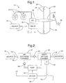
- a motor vehicle generally indicated as 10, includes a primary source of vacuum 12, which is typically an air induction passage of a vehicle engine but could alternatively be a motor driven vacuum pump.
- a vehicle power brake system includes a brake booster 20 that receives an input brake activation force from a brake pedal 22 and communicates the activation force to a master cylinder 24, and thus to one or more vehicle brake units 21, through a valve and power piston apparatus 25 of known construction in the normal manner.
- a portion of the body of booster 20 is divided by a diaphragm 26 into a vacuum chamber 27 and a working chamber 28 to create a differential pressure actuator.
- Vacuum chamber 27 is connected to vacuum source 12 through a conduit 14 and vacuum assist unit 30.
- Unit 30 contains an electric motor driven pump and check valve apparatus, to be described below, to ensure a vacuum supply for vacuum chamber 27; and a substantially constant vacuum level, relative to atmospheric pressure, is maintained in vacuum chamber 27, normally by vacuum source 12 but, if required, by assist unit 30.
- Working chamber 28 is controlled by a multiple valve apparatus, not shown, to normally maintain the supplied vacuum when brake pedal 22 is not activated but to admit atmospheric air in response to activation of brake pedal 22 so as to provide pressure on diaphragm 26 to the left in FIG 1. This pressure is communicated by diaphragm 26, through apparatus not shown, as an output brake assist force to master cylinder 24.
- the parts of brake booster 20 not shown are standard in construction and operation, the details of which are well known in the art and unimportant to this invention. Examples may be found in US Patent No. 3,249,021 to Wuellner and US Patent No. 4,069,742 to Gephart et al, as well as many others.
- Vacuum assist unit 30 is shown in its preferred position, attached directly to booster 20, in FIG. 3.
- the unit is attached by means of one or more mounting brackets 32 assembled on threaded studs 34 and held tightly thereon with nuts 36.
- Rubber isolators 38 may be used between brackets 32 and the body of unit 30 to reduce the transmission of motor and pump noise from unit 30 to booster 20.
- Studs 34 may be welded directly to the case of booster 20; and two such studs will provide sufficient support, with a third support point provided for a fitting 40 providing fluid communication from unit 30 directly into booster 20 without the need for a vacuum hose therebetween.
- Another fitting 42 accepts conduit 14 and communicates unit 30 to vacuum source 12.
- An electrical connector 44 is provided for connection of electrical devices and circuits within unit 30 to a vehicle wiring harness.
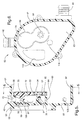
- FIG. 2 shows a schematic diagram of unit 30 and its vacuum connections to source 12 and booster 20.
- Booster 20 is connected through fitting 40 of unit 30 to a vacuum assist chamber 80, which includes an integral pressure sensor 81 for vacuum within the chamber relative to atmosphere.
- Vacuum assist chamber 80 is connected via a check valve 93 to an air exhaust chamber 72 so that air flows only from chamber 80 to chamber 72.
- Chamber 72 is connected via fitting 42 of unit 30 and conduit 14 to vacuum source 12.
- Vacuum assist chamber 80 is also connected to the air inlet of a pump 62; and the air outlet of pump 62 is connected via a check valve 99 to air exhaust chamber 72. Pump 62 may thus pump air only from chamber 80 to chamber 72.
- Motor 60 is electrically connected in series with a switch 79 across a voltage +V and mechanically drives pump 62 when the switch is activated to a closed position.
- Switch 79 is responsive to sensor 81 to close when the sensed vacuum within assist chamber 80, and thus within vacuum chamber 27 of booster 20, falls below a predetermined minimum desired level.
- Switch 79 is preferably a semiconductor switch in a switch control circuit on circuit board 74, the circuit being responsive to the output of sensor 81 and most probably containing a programmed microprocessor.
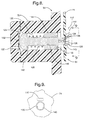
- Vacuum assist unit 30 is shown in cross section in FIG. 4 and in perspective in FIG. 7.
- a housing for unit 30 comprises three parts: a motor/pump housing 50, a manifold housing 52 and an end cap 54.
- Motor/pump housing 50 preferably made of aluminum or steel but possibly thermo-plastic, contains an electric motor 60 and an air pump 62, in this embodiment shown as a vane pump, adapted to be driven by motor 60.
- An open axial end 64 of motor/pump housing 50 is affixed to an axial side 65 of manifold housing 52, with an O-ring seal and isolation member 66.
- End cap 54 made of a thermo-plastic material, is affixed to the opposite axial side 67 of manifold housing 52, in a connection that is also sealed.
- An internal divider member 70 internally affixed to manifold housing helps create a wall that divides the interior of manifold housing 52 and end cap 54 into air exhaust chamber 72 and assist vacuum chamber 80.
- Air exhaust chamber 72 is open through an opening 73 to fitting 42.
- End cap 54 includes a circuit board 74 affixed thereto on a plurality of studs 75 so as to be contained within assist vacuum chamber 80.
- End cap 54 further includes an integral connector fitting 76, through which project electrical connecting terminals 77 having one end connected to circuitry on circuit board 74 within chamber 80 and another end projecting out of unit 30 for connection to a vehicle wiring harness.
- End cap 54 further includes a pressure sensor housing portion 78 housing a differential pressure diaphragm and magnet tipped plunger for use with a Hall effect sensor 110 mounted on circuit board 74. The pressure sensing arrangement is described in greater detail with respect to FIG. 8.
- Manifold housing 52 is shown in an enlarged section viewed from the opposite side in FIG. 5 and, in a section normal to that of FIG. 5, in FIG. 6.
- Manifold housing 52 made of a thermo-plastic material, comprises a main, cup-shaped, outer portion 82 with a wall 83 at one axial end and open at the opposite axial end.
- Another wall 84 extends generally axially from wall 83 toward the open end and defines a receptacle 85 for internal divider member 70, which is fixed in a sealing manner therein to create air exhaust chamber 72.
- An axial projection 90 projects from wall 83 toward the open end of housing 52 to engage an axial projection 91 projecting in the opposite direction from divider member 70.
- a valve seat 92 is formed on the surface of divider member 70 surrounding projection 91; and a movable valve element 93 is retained adjacent valve seat 92 to close one or more openings 94 when the pressure in air exhaust chamber 72 exceeds that in assist vacuum chamber 80. Opening 73 is provided from air exhaust chamber 72 to fitting 42, and thus through conduit 14 to vacuum source 12. Elements 90-94 define a check valve that automatically applies the vacuum of vacuum source 12 to assist vacuum chamber 80.
- a short circular wall 101 projects from the side of wall 83 opposite air exhaust chamber 72 and is provided with a circular groove 102 to receive sealing O-ring 66 (shown in FIG. 4). Openings 100 are sealingly connected to the air outlet of pump 62, with the air inlet of pump 62 being connected to assist vacuum chamber 80 through opening 114 (shown in FIG. 6).
- Elements 96-100 thus define a check valve that automatically applies the vacuum created by pump 62 to assist vacuum chamber 80, which is thus maintained at the greater of the vacuum from vacuum source 12 and the vacuum created by pump 62.
- Assist vacuum chamber 80 is open through an opening 105 in outer portion 82 of manifold housing 52 and fitting 40 to vacuum chamber 27 of booster 20, which is thus also maintained at the same vacuum level.
- the placement of the check valve including element 99 in the outlet path of pump 62 provides a small pressure drop that improves pump efficiency and thus contributes to the compactness of unit 30.
- a cylindrical recess 120 is provided in sensor fitting 78 of end cap 54. Recess 120 is open to assist vacuum chamber 80 at its inner end and, through an opening 122, to outside atmosphere at its opposite end.
- a flexible diaphragm 124 adjacent opening 122 prevents fluid communication between cylindrical recess 120 and the atmosphere and is subject to a differential pressure equal to the vacuum level, relative to atmosphere, in assist vacuum chamber 80.
- a plunger 130 is disposed in cylindrical recess 120 for axial movement therein. Plunger 130 has a diaphragm contacting head 132 at the end adjacent diaphragm 124 and an opposite axial end 134 projecting into vacuum assist chamber 80 and through a guide opening 126 in circuit board 74.
- Diaphragm 124 is preferably a rolling diaphragm so as to eliminate or reduce tension effects in the clamped portion of the diaphragm.
- a permanent magnet 140 is mounted on end 134 of plunger 130 in an axially adjustable manner, such as by mounting on a flat head screw 136 threadably inserted into an axial opening 138 on end 134 of plunger 130.
- plunger 130, screw 136 and other parts near magnet 140 are made of appropriate non-magnetic materials.
- Magnet 140 is magnetized axially, with north and south poles at opposing axial ends thereof.
- Plunger 130 is biased outwardly from chamber 80, into engagement with diaphragm 124, by a coil spring 142 reacting against a spring base member 144 which may be threadably adjustable within cylindrical recess 120 and has an opening 146 therethrough for plunger 130.
- Spring base member 144 may be positionally adjusted during assembly of unit 30 to provide a desired spring preload; and openings 148 may be provided for the insertion of a tool, before positioning of circuit board 74, to rotate spring base member 144 for such adjustment.
- the preload should be adjusted as sufficient to prevent movement of the plunger by forces other than a pressure differential across diaphragm 124 but low enough to allow response of the plunger to the minimum desired sensed pressure across diaphragm 124, as is known to those of skill in the art.
- the diaphragm 124, plunger head 132 and magnet 140 are shown in one extreme position in solid lines and, in another extreme position, in dashed lines.
- the pressure sensing system is essentially used as a switch, to activate motor 60 and thus drive pump 62 when sensed vacuum in assist vacuum chamber 80, which is essentially the same as that in vacuum chamber 27 of booster 20, falls below a predetermined level, in order to maintain that level as a minimum, even if there is a failure of vacuum source 12.
- Hall effect sensor 110 is a temperature sensitive element that produces a voltage output, for a given relative position of magnet 140. Thus, the output voltage of Hall effect sensor 110 will vary with temperature as well as with the axial position of magnet 140. However, Hall effect sensor 110 defines a particular position, which may be called the temperature invariant axis 115, at which the voltage is independent of temperature. In the graph of FIG.
- FIG. 6 shows an opening 112 in wall 83 of manifold housing 52 that communicates assist vacuum chamber 80 with the interior of motor/pump housing 50, so that electrical connections, not shown, may be provided between motor 60 and circuit board 74 within chamber 80.
- all electrical apparatus in unit 30, including motor 60, sensor 81 and circuit board 74 are maintained in a vacuum environment, which is repeatedly and continuously pumped free of contaminants and corrosion causing moisture whenever the vehicle is being operated, whether the vacuum is provided by pump 62 or vacuum source 12.
Landscapes
- Engineering & Computer Science (AREA)
- Transportation (AREA)
- Mechanical Engineering (AREA)
- Valves And Accessory Devices For Braking Systems (AREA)
- Braking Systems And Boosters (AREA)
Abstract
Description
Claims (19)
- A self contained, supplemental vacuum assist unit for use with a vacuum brake booster 20 and a source of vacuum 12 in a motor vehicle, the vacuum brake booster having a vacuum chamber 27 and a working pressure chamber 28, the unit comprising, in combination:a housing 50, 52, 54 defining an assist vacuum chamber 80 having an opening 105 with a fitting 40 adapted for connection to the vacuum chamber of the vacuum brake booster and further defining an air exhaust chamber 72 having an opening 73 with a fitting 42 adapted for connection to the source of vacuum, the assist vacuum chamber and the air exhaust chamber being separated by a wall 70;a first opening 94 in the wall having a first unidirectional flow valve 93 permitting air flow only from the assist vacuum chamber to the air exhaust chamber;an electric motor driven air pump 62 in the housing having an inlet 114 from the assist vacuum chamber and an outlet 100 to the air exhaust chamber, the pump having associated therewith a second unidirectional flow valve 99 permitting air flow through the air pump only from the assist vacuum chamber to the air exhaust chamber;an electric circuit board 74 within the assist vacuum chamber having a Hall effect sensor 110 thereon so as to sense a magnetic field adjacent the sensor and a control circuit thereon responsive to the Hall effect sensor to control operation of the electric motor driven air pump;the housing further defining an opening 122 from the assist vacuum chamber to a source of air at atmospheric pressure, the opening being closed by a flexible diaphragm 124;a plunger 130 activated by the diaphragm for axial movement therewith due to changes in pressure across the diaphragm; anda permanent magnet 140 affixed to the plunger adjacent the Hall effect sensor, the permanent magnet generating a magnetic field sensed by the Hall effect sensor and the Hall effect sensor being responsive thereto to generate a signal changing with the position of the permanent magnet and thus with the pressure across the diaphragm.
- The self contained, supplemental vacuum assist unit of claim 1 in which the electric circuit board is adapted to guide the motion of the plunger in a predetermined direction relative to the Hall effect sensor.
- The self contained, supplemental vacuum assist unit of claim 1 in which the permanent magnet is affixed on an end 134 of the plunger in an axially adjustable manner.
- The self contained, supplemental vacuum assist unit Of claim 3 in which the permanent magnet is affixed on an end of the plunger in an axial position relative thereto to cross a temperature invariant axis of the Hall effect sensor at a predetermined pressure across the diaphragm corresponding to a minimum desired vacuum level in the vacuum chamber of the vacuum brake booster.
- The self contained, supplemental vacuum assist unit of claim 3 in which the diaphragm and plunger are biased by a spring 142 reacting against a spring seat member adjustable to vary the spring preload.
- The self contained, supplemental vacuum assist unit of claim 1 in which one or more brackets 32 are provided for mounting the unit directly on a vacuum booster and the fitting is adapted to directly engage the booster and thus communicate the assist vacuum chamber to the vacuum chamber of the booster, without the use of intervening, removable conduits between the unit and the booster, when the unit is so mounted.
- The self contained, supplemental vacuum assist unit of claim 6 further having two levels of sound isolation apparatus between the electric motor in the unit and the booster: first sound isolating mounting devices 38 associated with the brackets, and second sound isolating mounting devices 56 between the electric motor and housing of the unit.
- The self contained, supplemental vacuum assist unit of claim 1 in which the second unidirectional valve is disposed downstream of the outlet of the air pump.
- The self contained, supplemental vacuum assist unit of claim 1 in which the housing comprises a manifold housing 52 with an end cap 54, the manifold housing including the wall dividing the manifold housing into the vacuum assist chamber and the air exhaust chamber, and the end cap completing the assist vacuum chamber, holding the diaphragm, plunger and magnet of the sensor, and supporting the circuit board and external electrical connection apparatus therefrom.
- The self contained, supplemental vacuum assist unit of claim 9 in which the housing further comprises a motor/pump housing 50 attached to the manifold housing and having an opening 112 to the assist vacuum chamber through which electrical connection is provided therefrom to the motor, whereby the magnet, circuit board, Hall effect sensor and motor are all maintained within the vacuum supplied to the booster, regardless of the source of such vacuum.
- Vehicle power brake assist apparatus for use with a source of vacuum 12 in a motor vehicle, the apparatus comprising a vacuum brake booster 20 and a supplemental vacuum assist unit 30, the vacuum brake booster having a vacuum chamber 27 and a working pressure chamber 28, the supplemental vacuum assist unit being affixed to the vacuum brake booster by one or more brackets 32 and comprising, in combination:a housing 50, 52, 54 defining an assist vacuum chamber 80 having an opening 105 with a fitting 40 directly communicating with the vacuum chamber of the vacuum brake booster and further defining an air exhaust chamber 72 having an opening 73 with a fitting 42 adapted for connection to the source of vacuum, the assist vacuum chamber and the air exhaust chamber being separated by a wall 70;a first opening 94 in the wall having a first unidirectional flow valve 93 permitting air flow only from the assist vacuum chamber to the air exhaust chamber;an electric motor driven air pump 62 in the housing having an inlet 114 from the assist vacuum chamber and an outlet 100 to the air exhaust chamber, the pump having associated therewith a second unidirectional flow valve 99 permitting air flow through the air pump only from the assist vacuum chamber to the air exhaust chamber;an electric circuit board 74 within the assist vacuum chamber having a Hall effect sensor 110 thereon so as to sense a magnetic field adjacent the sensor and a control circuit thereon responsive to the Hall effect sensor to control operation of the electric motor driven air pump;the housing further defining an opening 122 from the assist vacuum chamber to a source of air at atmospheric pressure, the opening being closed by a flexible diaphragm 124;a plunger 130 activated by the diaphragm for axial movement therewith due to changes in pressure across the diaphragm;a permanent magnet 140 affixed to the plunger adjacent the Hall effect sensor, the permanent magnet generating a magnetic field sensed by the Hall effect sensor and the Hall effect sensor being responsive thereto to generate a signal changing with the position of the permanent magnet and thus with the pressure across the diaphragm.
- The vehicle power brake assist apparatus of claim 11 in which the electric circuit board is adapted to guide the motion of the plunger in a predetermined direction relative to the Hall effect sensor.
- The vehicle power brake assist apparatus of claim 11 in which the permanent magnet is affixed on an end 134 of the plunger in an axially adjustable manner.
- The vehicle power brake assist apparatus of claim 13 in which the permanent magnet is affixed on the end of the plunger in an axial position relative thereto to cross a temperature invariant axis of the Hall effect sensor at a predetermined pressure across the diaphragm corresponding to a minimum desired vacuum level in the vacuum chamber of the vacuum brake booster.
- The vehicle power brake assist apparatus of claim 13 in which the diaphragm and plunger are biased by a spring 142 reacting against a spring seat member adjustable to vary the spring preload.
- The vehicle power brake assist apparatus of claim 11 in which the second unidirectional valve is disposed downstream of the outlet of the air pump.
- The vehicle power brake assist apparatus of claim 11 in which the housing comprises a manifold housing 52 with an end cap 54, the manifold housing including the wall 70 dividing the manifold housing into the vacuum assist chamber and the air exhaust chamber, and the end cap completing the assist vacuum chamber, holding the diaphragm, plunger and magnet of the sensor, and supporting the circuit board and external electrical connection apparatus therefrom.
- The vehicle power brake assist apparatus of claim 17 in which the housing further comprises a motor/pump housing 50 attached to the manifold housing and having an opening 112 to the assist vacuum chamber through which electrical connection is provided therefrom to the motor, whereby the magnet, circuit board, Hall effect sensor and motor are all maintained within the vacuum supplied to the booster, regardless of the source of such vacuum.
- The vehicle power brake assist apparatus of claim 11 further having two levels of sound isolation apparatus between the electric motor in the unit and the booster: first sound isolating mounting devices 38 associated with the brackets, and second sound isolating mounting devices 56 between the electric motor and housing of the unit.
Applications Claiming Priority (2)
| Application Number | Priority Date | Filing Date | Title |
|---|---|---|---|
| US602783 | 1984-04-23 | ||
| US09/602,783 US6324845B1 (en) | 2000-06-23 | 2000-06-23 | Self contained, supplemental vacuum assist unit for vehicle brake booster |
Publications (3)
| Publication Number | Publication Date |
|---|---|
| EP1167149A2 true EP1167149A2 (en) | 2002-01-02 |
| EP1167149A3 EP1167149A3 (en) | 2003-12-17 |
| EP1167149B1 EP1167149B1 (en) | 2005-12-07 |
Family
ID=24412789
Family Applications (1)
| Application Number | Title | Priority Date | Filing Date |
|---|---|---|---|
| EP01202343A Expired - Lifetime EP1167149B1 (en) | 2000-06-23 | 2001-06-18 | Self contained, supplemental vacuum assist unit for vehicule brake booster |
Country Status (3)
| Country | Link |
|---|---|
| US (1) | US6324845B1 (en) |
| EP (1) | EP1167149B1 (en) |
| DE (1) | DE60115543T2 (en) |
Cited By (3)
| Publication number | Priority date | Publication date | Assignee | Title |
|---|---|---|---|---|
| CN102371984A (en) * | 2011-08-29 | 2012-03-14 | 温州大学 | Vacuum boosting device of electric vehicle |
| CN105197001A (en) * | 2015-11-05 | 2015-12-30 | 昆山市兴利车辆科技配套有限公司 | Vacuum pump controller of electric vehicle |
| CN107697054A (en) * | 2017-09-18 | 2018-02-16 | 北京长城华冠汽车科技股份有限公司 | A kind of modification method and device of vacuum servo parameter |
Families Citing this family (36)
| Publication number | Priority date | Publication date | Assignee | Title |
|---|---|---|---|---|
| DE10061152A1 (en) * | 2000-12-08 | 2002-06-27 | Lucas Varity Gmbh | Sensor arrangement for a vacuum brake booster and a vacuum brake booster equipped with it |
| US6719477B2 (en) | 2001-11-02 | 2004-04-13 | Delphi Technologies, Inc. | Spacer for vacuum brake booster |
| US6774592B2 (en) * | 2001-12-03 | 2004-08-10 | Delphi Technologies, Inc. | Method and system for controlling a permanent magnet machine |
| US6758041B2 (en) * | 2002-09-12 | 2004-07-06 | Delphi Technologies, Inc. | Electric power brake booster |
| FR2844494B1 (en) * | 2002-09-12 | 2004-11-26 | Bosch Sist De Frenado Sl | BRAKING DEVICE FOR A MOTOR VEHICLE COMPRISING AN EMPTY PUMP |
| DE10248848A1 (en) * | 2002-10-19 | 2004-05-06 | Dr.Ing.H.C. F. Porsche Ag | Arrangement for producing vacuum for motor vehicle brake booster has vacuum pump activated as required according to operating conditions and driven simultaneously with secondary air pump switch-on |
| JP4158507B2 (en) * | 2002-12-05 | 2008-10-01 | トヨタ自動車株式会社 | Valve drive system for internal combustion engine |
| US6964609B2 (en) * | 2003-05-28 | 2005-11-15 | Igt | Gaming device having alternate outcome presentations |
| US6912946B2 (en) * | 2003-05-28 | 2005-07-05 | Delphi Technologies, Inc. | System and method for improved controlled airflow within a vacuum booster system |
| US20050039597A1 (en) * | 2003-08-19 | 2005-02-24 | Delphi Technologies Inc. | Modular valve assembly for a vacuum booster |
| CN100434315C (en) * | 2004-06-17 | 2008-11-19 | 大陆-特韦斯贸易合伙股份公司及两合公司 | Method for providing a vacuum in a vacuum chamber of a pneumatic brake booster |
| DE102005027768A1 (en) * | 2004-06-17 | 2006-04-20 | Continental Teves Ag & Co. Ohg | Method for providing negative pressure in a vacuum chamber of a pneumatic brake booster |
| DE102005036615A1 (en) * | 2004-08-06 | 2006-02-23 | Continental Teves Ag & Co. Ohg | Device for providing pressure for an actuating unit of a motor vehicle brake system and method for controlling the device |
| FR2877629A1 (en) * | 2004-11-05 | 2006-05-12 | Renault Sas | MOTOR VEHICLE HAVING A DEVICE FOR MANAGING A VACUUM PUMP CONNECTED TO A BRAKING SYSTEM |
| EP1681218A1 (en) * | 2005-01-15 | 2006-07-19 | LuK Automobiltechnik GmbH & Co. KG | Negative pressure brake booster |
| EP1681219B1 (en) * | 2005-01-18 | 2008-05-21 | Fuji Jukogyo Kabushiki Kaisha | Control system for a brake booster vacuum pump |
| US20070222282A1 (en) * | 2006-03-27 | 2007-09-27 | Thurm Kenneth R | Motorcycle brake connector |
| JP5039125B2 (en) * | 2006-04-14 | 2012-10-03 | ワイケイ フエン, | Vacuum assist pump system |
| DE102008007593A1 (en) * | 2008-01-25 | 2009-09-03 | Basar Gmbh | Device for measuring geometry on a workpiece and method for measuring geometry on a workpiece |
| EP2396554A4 (en) * | 2009-02-13 | 2017-05-24 | Davey Water Products Pty Ltd | Controller for a liquid supply pump |
| JP2013532320A (en) * | 2010-05-11 | 2013-08-15 | コンティ・テミック・マイクロエレクトロニック・ゲーエムベーハー | Drive pedal unit for automobile |
| DE102010027308A1 (en) * | 2010-07-16 | 2012-01-19 | Lucas Automotive Gmbh | Sensor assembly for a master cylinder |
| US9452746B2 (en) * | 2010-10-01 | 2016-09-27 | GM Global Technology Operations LLC | System and method for controlling a flow of air |
| FR2966410A1 (en) * | 2010-10-20 | 2012-04-27 | Peugeot Citroen Automobiles Sa | Pneumatic circuit for assistance of braking of motor vehicle, has control device and sluice gate for operating accelerator, where average control laid out of conduit enters end of conduit close to vacuum source and accelerator |
| FR2977549A1 (en) * | 2011-07-07 | 2013-01-11 | Peugeot Citroen Automobiles Sa | Vacuum generator device for assisting braking system of diesel engine of e.g. hybrid car, has main vacuum pump whose shaft is permanently driven by wheels of car, where auxiliary unit of vacuum generator is operated independent of pump |
| US10065618B2 (en) * | 2013-04-12 | 2018-09-04 | Ford Global Technologies, Llc | Vehicle braking system and method |
| JP6066113B2 (en) * | 2014-08-19 | 2017-01-25 | トヨタ自動車株式会社 | Control device for electric vacuum pump |
| DE102015217520A1 (en) * | 2015-09-14 | 2017-03-16 | Robert Bosch Gmbh | Electromechanical brake booster and brake system |
| FR3048504B1 (en) * | 2016-03-07 | 2018-03-16 | Peugeot Citroen Automobiles Sa | PRESSURE SENSOR FOR BRAKE ASSIST AMPLIFIER INCLUDING INTEGRATED ANTI-RETURN VALVE |
| CN109026612A (en) * | 2018-06-14 | 2018-12-18 | 安徽安凯汽车股份有限公司 | A kind of intelligent heat dissipation system for integral new-energy passenger inflating pump |
| CN109572648A (en) * | 2018-10-23 | 2019-04-05 | 湖州知谷汽车零部件有限公司 | A kind of controller for vacuum pump and control method |
| CN109572649B (en) * | 2018-12-30 | 2023-10-24 | 吉林东光奥威汽车制动系统有限公司 | Electric vacuum pump control device suitable for plateau and plateau areas |
| KR102681632B1 (en) * | 2019-02-15 | 2024-07-08 | 현대자동차주식회사 | Waterproof Chamber Type Electric Vacuum Pump and Vacuum Boosting Brake System Thereby |
| US12290484B2 (en) | 2021-06-30 | 2025-05-06 | Hill-Rom Services, Inc. | Manifold assembly for pneumatic system |
| CN119855574A (en) | 2022-09-09 | 2025-04-18 | 希尔-罗姆服务公司 | Manifold Assemblies |
| US20240149858A1 (en) * | 2022-11-07 | 2024-05-09 | Bendix Commercial Vehicle Systems Llc | System, method and device for implementing a dual air supply for braking systems |
Family Cites Families (20)
| Publication number | Priority date | Publication date | Assignee | Title |
|---|---|---|---|---|
| US3094843A (en) * | 1960-03-18 | 1963-06-25 | Bendix Corp | Automatic emergency power for vacuum powered braking systems |
| US4043123A (en) * | 1975-12-09 | 1977-08-23 | Toyota Jidosha Kogyo Kabushiki Kaisha | Negative pressure generating system for internal combustion engine powered vehicles |
| US4328669A (en) | 1980-02-15 | 1982-05-11 | General Motors Corporation | Vacuum power system and regulator therefor |
| US4332302A (en) | 1980-07-28 | 1982-06-01 | General Motors Corporation | Vehicle vacuum supply system |
| US4358928A (en) | 1980-08-28 | 1982-11-16 | General Motors Corporation | Altitude compensation vacuum pump control |
| JPS57164854A (en) * | 1981-03-31 | 1982-10-09 | Nissin Kogyo Kk | Negative pressure source in negative pressure type booster for automobile |
| KR870002377A (en) * | 1985-08-05 | 1987-03-31 | 미다 가쓰시게 | Negative pressure supply device for automobile |
| JPS6261868A (en) * | 1985-09-10 | 1987-03-18 | Toyota Motor Corp | Drive controller for motor negative pressure pump |
| US4790937A (en) | 1986-05-20 | 1988-12-13 | Cobe Laboratories, Inc. | Diaphragm and chamber device |
| US4897184A (en) | 1986-10-31 | 1990-01-30 | Cobe Laboratories, Inc. | Fluid flow apparatus control and monitoring |
| US5024294A (en) | 1990-06-07 | 1991-06-18 | Johnson Service Company | Differential pressure transducer |
| US5717135A (en) | 1991-09-30 | 1998-02-10 | Carl A. Fiorletta | Tire pressure monitoring system utilizing a pressure activated transducer and sensor |
| US5219041A (en) | 1992-06-02 | 1993-06-15 | Johnson Service Corp. | Differential pressure sensor for screw compressors |
| TW271424B (en) * | 1992-12-11 | 1996-03-01 | Tokico Ltd | |
| DE4416833A1 (en) * | 1994-05-16 | 1995-11-23 | Teves Gmbh Alfred | Brake system for motor vehicles with a pneumatic brake booster |
| US5881557A (en) * | 1997-06-16 | 1999-03-16 | Shields; David A. | Vacuum system for diesels and high performance vehicles |
| DE19851859C1 (en) * | 1998-11-10 | 2000-04-13 | Lucas Ind Plc | Vacuum pump for motor vehicle brake servo has releasable drive coupling actuated by diaphragm exposed to operating vacuum |
| DE19853050A1 (en) * | 1998-11-17 | 2000-05-25 | Lucas Ind Plc | Vacuum braking pressure amplifier vacuum pump has deflectable membrane bounding working chamber, actuator coupled to membrane with armature moved by electromagnetic coil |
| US6164183A (en) * | 1999-02-10 | 2000-12-26 | Delphi Technologies, Inc. | Brake booster with alternate activation by rotary electric motor |
| US6255941B1 (en) * | 2000-02-24 | 2001-07-03 | Indian Head Industries, Inc. | Brake monitoring system |
-
2000
- 2000-06-23 US US09/602,783 patent/US6324845B1/en not_active Expired - Lifetime
-
2001
- 2001-06-18 DE DE60115543T patent/DE60115543T2/en not_active Expired - Lifetime
- 2001-06-18 EP EP01202343A patent/EP1167149B1/en not_active Expired - Lifetime
Cited By (4)
| Publication number | Priority date | Publication date | Assignee | Title |
|---|---|---|---|---|
| CN102371984A (en) * | 2011-08-29 | 2012-03-14 | 温州大学 | Vacuum boosting device of electric vehicle |
| CN105197001A (en) * | 2015-11-05 | 2015-12-30 | 昆山市兴利车辆科技配套有限公司 | Vacuum pump controller of electric vehicle |
| CN105197001B (en) * | 2015-11-05 | 2018-04-24 | 昆山市兴利车辆科技配套有限公司 | Vacuum pump of electric automobile controller |
| CN107697054A (en) * | 2017-09-18 | 2018-02-16 | 北京长城华冠汽车科技股份有限公司 | A kind of modification method and device of vacuum servo parameter |
Also Published As
| Publication number | Publication date |
|---|---|
| EP1167149B1 (en) | 2005-12-07 |
| US6324845B1 (en) | 2001-12-04 |
| DE60115543T2 (en) | 2006-06-22 |
| EP1167149A3 (en) | 2003-12-17 |
| DE60115543D1 (en) | 2006-01-12 |
Similar Documents
| Publication | Publication Date | Title |
|---|---|---|
| EP1167149B1 (en) | Self contained, supplemental vacuum assist unit for vehicule brake booster | |
| US10246071B2 (en) | Hydraulic pressure generating device | |
| US10207690B2 (en) | Brake apparatus | |
| CN107531225B (en) | Operating device for motor vehicle brakes | |
| KR101914884B1 (en) | Brake device and master cylinder | |
| US7051718B2 (en) | Fuel vapor leak check module | |
| JP6213730B2 (en) | Brake device | |
| US20190039590A1 (en) | Brake Apparatus, Brake System, and Master Cylinder | |
| US20130186082A1 (en) | Electric booster | |
| JP2018188147A (en) | Integrated air supply unit | |
| CA2314974A1 (en) | Air dryer reservoir module | |
| EP1452416A3 (en) | Air dryer reservoir module | |
| SK125196A3 (en) | Brake system for motor vehicles with pneumatic brake booster | |
| US20200254989A1 (en) | Hydraulic Control Device and Brake System | |
| US20190193706A1 (en) | Solenoid valve assembly for a braking system for a vehicle, braking system for a vehicle, and method for mounting a solenoid valve assembly for a braking system for a vehicle | |
| US6301883B1 (en) | Vehicle brake booster with supplemental vacuum assist | |
| JP4440634B2 (en) | Brake vacuum booster for vehicle brake device and method for driving vehicle brake device equipped with this brake vacuum booster | |
| US20010009881A1 (en) | Control system for a transmission | |
| WO2017043269A1 (en) | Electromagnetic valve, hydraulic control device, and brake device | |
| WO1997043558A1 (en) | Hydraulic brake booster | |
| US7059177B2 (en) | Fuel vapor leak check module | |
| CN109311459B (en) | Hydraulic control device and braking system | |
| US20050044936A1 (en) | Fuel vapor leak check module | |
| US6626150B2 (en) | Electronically controlled continuous fuel pressure regulator | |
| KR19990023244A (en) | Electrically actuated and compressed air operated valve assembly |
Legal Events
| Date | Code | Title | Description |
|---|---|---|---|
| PUAI | Public reference made under article 153(3) epc to a published international application that has entered the european phase |
Free format text: ORIGINAL CODE: 0009012 |
|
| AK | Designated contracting states |
Kind code of ref document: A2 Designated state(s): AT BE CH CY DE DK ES FI FR GB GR IE IT LI LU MC NL PT SE TR |
|
| AX | Request for extension of the european patent |
Free format text: AL;LT;LV;MK;RO;SI |
|
| PUAL | Search report despatched |
Free format text: ORIGINAL CODE: 0009013 |
|
| AK | Designated contracting states |
Kind code of ref document: A3 Designated state(s): AT BE CH CY DE DK ES FI FR GB GR IE IT LI LU MC NL PT SE TR |
|
| AX | Request for extension of the european patent |
Extension state: AL LT LV MK RO SI |
|
| 17P | Request for examination filed |
Effective date: 20040617 |
|
| 17Q | First examination report despatched |
Effective date: 20040722 |
|
| AKX | Designation fees paid |
Designated state(s): DE FR GB IT |
|
| GRAP | Despatch of communication of intention to grant a patent |
Free format text: ORIGINAL CODE: EPIDOSNIGR1 |
|
| GRAS | Grant fee paid |
Free format text: ORIGINAL CODE: EPIDOSNIGR3 |
|
| GRAA | (expected) grant |
Free format text: ORIGINAL CODE: 0009210 |
|
| AK | Designated contracting states |
Kind code of ref document: B1 Designated state(s): DE FR GB IT |
|
| PG25 | Lapsed in a contracting state [announced via postgrant information from national office to epo] |
Ref country code: IT Free format text: LAPSE BECAUSE OF FAILURE TO SUBMIT A TRANSLATION OF THE DESCRIPTION OR TO PAY THE FEE WITHIN THE PRESCRIBED TIME-LIMIT;WARNING: LAPSES OF ITALIAN PATENTS WITH EFFECTIVE DATE BEFORE 2007 MAY HAVE OCCURRED AT ANY TIME BEFORE 2007. THE CORRECT EFFECTIVE DATE MAY BE DIFFERENT FROM THE ONE RECORDED. Effective date: 20051207 |
|
| REG | Reference to a national code |
Ref country code: GB Ref legal event code: FG4D |
|
| REF | Corresponds to: |
Ref document number: 60115543 Country of ref document: DE Date of ref document: 20060112 Kind code of ref document: P |
|
| PG25 | Lapsed in a contracting state [announced via postgrant information from national office to epo] |
Ref country code: GB Free format text: LAPSE BECAUSE OF NON-PAYMENT OF DUE FEES Effective date: 20060618 |
|
| PLBE | No opposition filed within time limit |
Free format text: ORIGINAL CODE: 0009261 |
|
| STAA | Information on the status of an ep patent application or granted ep patent |
Free format text: STATUS: NO OPPOSITION FILED WITHIN TIME LIMIT |
|
| 26N | No opposition filed |
Effective date: 20060908 |
|
| EN | Fr: translation not filed | ||
| GBPC | Gb: european patent ceased through non-payment of renewal fee |
Effective date: 20060618 |
|
| PG25 | Lapsed in a contracting state [announced via postgrant information from national office to epo] |
Ref country code: FR Free format text: LAPSE BECAUSE OF FAILURE TO SUBMIT A TRANSLATION OF THE DESCRIPTION OR TO PAY THE FEE WITHIN THE PRESCRIBED TIME-LIMIT Effective date: 20070126 |
|
| PG25 | Lapsed in a contracting state [announced via postgrant information from national office to epo] |
Ref country code: FR Free format text: LAPSE BECAUSE OF FAILURE TO SUBMIT A TRANSLATION OF THE DESCRIPTION OR TO PAY THE FEE WITHIN THE PRESCRIBED TIME-LIMIT Effective date: 20051207 |
|
| PGFP | Annual fee paid to national office [announced via postgrant information from national office to epo] |
Ref country code: DE Payment date: 20170613 Year of fee payment: 17 |
|
| REG | Reference to a national code |
Ref country code: DE Ref legal event code: R119 Ref document number: 60115543 Country of ref document: DE |
|
| PG25 | Lapsed in a contracting state [announced via postgrant information from national office to epo] |
Ref country code: DE Free format text: LAPSE BECAUSE OF NON-PAYMENT OF DUE FEES Effective date: 20190101 |
|
| REG | Reference to a national code |
Ref country code: DE Ref legal event code: R081 Ref document number: 60115543 Country of ref document: DE Owner name: BWI COMPANY LIMITED S.A., LU Free format text: FORMER OWNER: DELPHI TECHNOLOGIES, INC., TROY, MICH., US Ref country code: DE Ref legal event code: R082 Ref document number: 60115543 Country of ref document: DE |