EP1167137A2 - Window wiper arm drive and window lock system - Google Patents
Window wiper arm drive and window lock system Download PDFInfo
- Publication number
- EP1167137A2 EP1167137A2 EP20010115286 EP01115286A EP1167137A2 EP 1167137 A2 EP1167137 A2 EP 1167137A2 EP 20010115286 EP20010115286 EP 20010115286 EP 01115286 A EP01115286 A EP 01115286A EP 1167137 A2 EP1167137 A2 EP 1167137A2
- Authority
- EP
- European Patent Office
- Prior art keywords
- wiper arm
- window
- wiper
- drive
- recited
- Prior art date
- Legal status (The legal status is an assumption and is not a legal conclusion. Google has not performed a legal analysis and makes no representation as to the accuracy of the status listed.)
- Granted
Links
Images



Classifications
-
- E—FIXED CONSTRUCTIONS
- E05—LOCKS; KEYS; WINDOW OR DOOR FITTINGS; SAFES
- E05B—LOCKS; ACCESSORIES THEREFOR; HANDCUFFS
- E05B83/00—Vehicle locks specially adapted for particular types of wing or vehicle
- E05B83/16—Locks for luggage compartments, car boot lids or car bonnets
-
- B—PERFORMING OPERATIONS; TRANSPORTING
- B60—VEHICLES IN GENERAL
- B60S—SERVICING, CLEANING, REPAIRING, SUPPORTING, LIFTING, OR MANOEUVRING OF VEHICLES, NOT OTHERWISE PROVIDED FOR
- B60S1/00—Cleaning of vehicles
- B60S1/02—Cleaning windscreens, windows or optical devices
- B60S1/04—Wipers or the like, e.g. scrapers
- B60S1/06—Wipers or the like, e.g. scrapers characterised by the drive
- B60S1/08—Wipers or the like, e.g. scrapers characterised by the drive electrically driven
-
- B—PERFORMING OPERATIONS; TRANSPORTING
- B60—VEHICLES IN GENERAL
- B60S—SERVICING, CLEANING, REPAIRING, SUPPORTING, LIFTING, OR MANOEUVRING OF VEHICLES, NOT OTHERWISE PROVIDED FOR
- B60S1/00—Cleaning of vehicles
- B60S1/02—Cleaning windscreens, windows or optical devices
- B60S1/04—Wipers or the like, e.g. scrapers
- B60S1/32—Wipers or the like, e.g. scrapers characterised by constructional features of wiper blade arms or blades
- B60S1/34—Wiper arms; Mountings therefor
- B60S1/342—Wiper arms; Mountings therefor with means for temporarily uncoupling the wiper arm from the drive
-
- B—PERFORMING OPERATIONS; TRANSPORTING
- B60—VEHICLES IN GENERAL
- B60S—SERVICING, CLEANING, REPAIRING, SUPPORTING, LIFTING, OR MANOEUVRING OF VEHICLES, NOT OTHERWISE PROVIDED FOR
- B60S1/00—Cleaning of vehicles
- B60S1/02—Cleaning windscreens, windows or optical devices
- B60S1/56—Cleaning windscreens, windows or optical devices specially adapted for cleaning other parts or devices than front windows or windscreens
- B60S1/58—Cleaning windscreens, windows or optical devices specially adapted for cleaning other parts or devices than front windows or windscreens for rear windows
- B60S1/583—Cleaning windscreens, windows or optical devices specially adapted for cleaning other parts or devices than front windows or windscreens for rear windows including wiping devices
-
- B—PERFORMING OPERATIONS; TRANSPORTING
- B60—VEHICLES IN GENERAL
- B60S—SERVICING, CLEANING, REPAIRING, SUPPORTING, LIFTING, OR MANOEUVRING OF VEHICLES, NOT OTHERWISE PROVIDED FOR
- B60S1/00—Cleaning of vehicles
- B60S1/02—Cleaning windscreens, windows or optical devices
- B60S1/04—Wipers or the like, e.g. scrapers
- B60S1/0452—Position of the wipers relative to the vehicle
- B60S1/0466—Arrangement of wipers on openable windows
-
- B—PERFORMING OPERATIONS; TRANSPORTING
- B60—VEHICLES IN GENERAL
- B60S—SERVICING, CLEANING, REPAIRING, SUPPORTING, LIFTING, OR MANOEUVRING OF VEHICLES, NOT OTHERWISE PROVIDED FOR
- B60S1/00—Cleaning of vehicles
- B60S1/02—Cleaning windscreens, windows or optical devices
- B60S1/04—Wipers or the like, e.g. scrapers
- B60S1/0491—Additional elements being fixed on wipers or parts of wipers not otherwise provided for, e.g. covers, antennae or lights
-
- E—FIXED CONSTRUCTIONS
- E05—LOCKS; KEYS; WINDOW OR DOOR FITTINGS; SAFES
- E05B—LOCKS; ACCESSORIES THEREFOR; HANDCUFFS
- E05B81/00—Power-actuated vehicle locks
- E05B81/12—Power-actuated vehicle locks characterised by the function or purpose of the powered actuators
- E05B81/13—Power-actuated vehicle locks characterised by the function or purpose of the powered actuators a single actuator for driving a lock and additional vehicle components, e.g. window wipers or window lifters
Definitions
- This invention relates to window wiper systems and, more particularly, to a wiper system and method for coupling a wiper arm to a drive motor and also for retaining a window in a closed position.
- a window wiper arm is mounted on a rear window hatch or door of a vehicle.
- the rear window is pivotable between an open and closed position to provide access inside the vehicle.
- the window wiper arm is usually directly coupled to a wiper motor which, in turn, is mounted directly on the window or below the window on the door.
- the window wiper arm is mounted on a wiper motor which is mounted on a rear door of a vehicle.
- the window wiper arm and wiper blade are driven below the bottom of the window to permit the rear window to swing open.
- this design approach has several disadvantages, including requiring and causing the wiper blade to be driven below the window and onto the door.
- the window requires a separate latch to latch and lock the window in a closed position. Because it is desired to place the window wiper arm at an approximate center of the rear window, this latch would have to be located "off center.” Because of the non-centered location of the window latch, it was not uncommon that the window would not seal properly to the door, thereby resulting in undesirable wind noise during vehicle operation or even water leakage into the interior compartment of the vehicle.
- both the latch assembly including any latch motor, and a window wiper motor were mounted in the door.
- Such systems oftentimes required the use of multiple motors and apparatus to accomplish the functions of wiping the window and locking the window in a closed position to the door.
- this invention comprises a wiper arm window latch system comprising a wiper arm rotatably mounted in a window for wiping a window, a drive motor for driving a wiper arm, and a drive coupler for coupling a wiper arm to a drive motor in order to latch a window to a door and also for coupling a wiper arm to a drive motor such that when a window is in a closed position a wiper arm may be rotatably driven by a drive motor.
- this invention comprises a wiper system comprising a wiper arm, a wiper system comprising a wiper motor comprising an output shaft having a drive latch assembly, a drive latch assembly comprising a latch release for detachably latching a wiper arm to a wiper motor so that a window becomes locked to a door, and a resilient detent for detachably coupling a wiper arm to an output shaft, regardless of a rotational position of a wiper arm.
- this invention comprises a method for locking a window onto a door and a wiper arm onto an output shaft of a motor comprising the steps of rotatably mounting a wiper arm onto a window, mounting a drive motor for driving a wiper arm onto a door, and situating a drive latch onto a drive motor, a drive latch latching a window to a door when a window is in a closed position and substantially simultaneously coupling a wiper arm to a drive motor such that when a window is in a closed position a wiper arm may be driven by a drive motor.
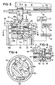
- a wiper arm window latch system 10 for use on a vehicle 12 having a window, such as a rear window 18 which is hingably attached to the vehicle 12 to permit movement between an open position (shown in Fig. 1) and a closed position (shown in Fig. 2).
- the wiper system 10 comprises a wiper arm 16 having a wiper blade 16a which is driven between a first wipe position A (shown in Fig. 2) to a second wipe position B in order to wipe the window 18 which is situated in a frame 20 (Fig. 1), free of debris, such as rain, snow or ice.
- the wiper arm window latch system 10 may be used with a window 18 which itself is hingably attached to the vehicle 12 without the use of a frame 20.
- the wiper arm window latch system 10 comprises a rotatable and generally cylindrical rotatable member or post 22 on which the wiper arm 16 is mounted.
- the rotatable member 22 cooperates with a receiving drive coupler 24 to couple the wiper arm 16 to an output shaft 26 (Fig. 3) of a drive motor 28 which is mounted in a door 30 (Figs. 1 and 2) of the vehicle.
- the drive coupler 24 not only couples the wiper arm 16 to the drive motor 28, but also provides the locking mechanism for retaining and locking the window 18 in the closed position shown in Fig. 2.
- the drive motor 28 may be any suitable drive motor for driving wiper arm 16, such as drive motor 4BE available from Valeo, Auburn Hills, MI.
- the drive motor 28 has the output shaft 26 which is secured by conventional means, such as a cotter pin, screw, key or retention ring to an end 24a of the drive coupler 24.
- the drive coupler 24 couples and locks the wiper arm 16 to the drive motor 28 in order to latch the window 18 to the door 30 (Fig. 2).
- the drive coupler 24 also couples the wiper arm 16 to the drive motor 28 so that when the window 18 is in the closed position, the drive motor 28 may be energized by a controller 32 in order to rotatably drive the wiper motor 28 between the wipe positions A and B (Fig. 2) in order to wipe the window 18 free of debris.
- the controller 32 is coupled to an operator switch 34 for controlling the operation of the wiper motor 28 in the manner described herein.
- the switch 34 is situated in the vehicle compartment 35 (Fig. 1) and may be any suitable switch, such as a rotary switch integrated into a turn signal indicator (not shown) or light control switch (not shown).
- the drive coupler 24 comprises a receiving area 36 for receiving the rotatable member 22 and for securing the rotatable member 22 to the wiper arm 16.
- the rotatable member 22 is rotatably secured in a bearing 38 in the window 18 as shown.
- the bearing 38 may be a ? (Rick, what type of bearing would this be mounted in ?) which, in turn, is mounted in an aperture 18a in the glass 18 as shown.
- the rotatable member 22 comprises means for securing the rotatable member 22 to the drive coupler 24.
- such means includes a plurality of recessed sockets 40 which cooperate with a plurality of balls 42 which are biased by springs 44 to lock into sockets 40 when the rotatable member 22 is fully received in receiving area 36 in order to lock the rotatable member 22 in the receiving area 36 of the drive coupler 24.
- any suitable means may be used to couple the rotatable member 22 to the drive coupler 24.
- the drive coupler 24 has a first end 24a mounted to the output shaft 26 of drive motor 28, as mentioned earlier, and a second end 24b rotatably mounted in a bearing 46 mentioned in a housing 48 in which the drive motor 28 is also securely mounted.
- the housing 48 may be integral with a housing 28a of drive motor 28.
- the bearing 46 may be a sleeve bearing or ball bearing.
- a feature of the wiper arm window latch system 10 is that it functions to retain, latch or lock the window 18 to the door 30 (Fig. 2) in order to retain the window 18 in a locked and closed position.
- the rotatable member 22 comprises a conically-shaped detent 50 (Fig. 3) and cylindrical connector portion 50b which is situated on an end 22a of the rotatable member 22.
- the detent 50 cooperates with a movable or actuatable lock or latch 52 which is driven among several positions, including a closed and locking position (shown in Figs. 3, 7 and 8), a partially open position (shown in Fig. 5) and a fully opened position (shown in Fig. 9). The movement among these positions will be described in further detail later herein.
- the latch system further comprises a spring 56 situated in drive coupler 24 for biasing and forcing a flange 50a of detent 50 against a bottom surface 52a of lock 52 when the drive coupler 24 is in the locked and latched position.
- the latch 52 comprises an aperture 51 in wall 52b for receiving the detent 50.
- the spring 56 biases the rotatable member 22 in the direction of arrow A in Fig. 3 so that when the lock 52 is actuated to an open position (shown in Fig. 9 as described later), the detent 50 of rotatable member 22 is biased out of wall 52b and the rotatable member 22 is actuated out of receiving area 36. This enables the wiper arm 16 to be forced, biased or actuated towards the open position shown in Fig. 1.
- conically-shaped flange 50a having an engaging surface 50c of detent 50 acts upon wall 52b to become driven in a direction opposite arrow A in Fig. 3 until flange 50a passes bottom surface 52a.
- wall 52b engages a cylindrical connector portion 50b which couples detent 50 to rotatable member 22.
- the lock 52 is biased by spring 54 to the right (as viewed in Fig. 6).
- spring 56 biases the rotatable member 22 in the direction of arrow A in Fig. 6 such that the surface 50c becomes biased against the bottom surface 52a. This causes the rotatable members 22 to be locked in drive coupler 24 and also causes the wiper arm 16 to be locked to drive motor 28, thereby also simultaneously locking window 18 to door 30.
- the lock 52 In order to cause the lock 52 to compress spring 54 and move to the left (as viewed in Fig. 6), the lock 52 is provided with a cam end 52c which is driven into engagement with a cam wall 58 on housing 48 when an operator actuates the operator switch 34 (Fig. 3) to open the window 18, as will be described later herein.
Landscapes
- Engineering & Computer Science (AREA)
- Mechanical Engineering (AREA)
- Power-Operated Mechanisms For Wings (AREA)
- Lock And Its Accessories (AREA)
- Window Of Vehicle (AREA)
Abstract
Description
Claims (63)
- A wiper arm window latch system comprising:a wiper arm rotatably mounted in a window for wiping said window;a drive motor for driving said wiper arm; anda drive coupler for coupling said wiper arm to said drive motor in order to latch said window to a door and also for coupling said wiper arm to said drive motor such that when said window is in a closed position said wiper arm may be rotatably driven by said drive motor.
- The wiper arm window latch system as recited in claim 1 wherein said drive latch comprises:a receiver for receiving an end of said wiper arm;a lock associated with said receiver for locking said wiper arm onto said receiver.
- The wiper arm window latch system as recited in claim 2 wherein said end comprises at least one groove, said lock comprising:
a resilient detent for cooperating with said at least one groove to lock said end of said wiper arm in said receiver. - The wiper arm window latch system as recited in claim 3 wherein said drive latch comprises an axis, said resilient detent comprises at least one spring-loaded ball biased towards said axis and received in said at least one groove to detachably lock said end of said wiper arm to said drive motor.
- The wiper arm window latch system as recited in claim 1 wherein an end of said window wiper arm comprises a wiper latch, said drive latch comprises:
a cam member which cooperates with said wiper latch to lock said window to said door and permitting said wiper arm to rotate when driven by said drive motor. - The wiper arm window latch system as recited in claim 5 wherein said drive latch further comprises a cam wall which said cam member engages when said drive motor drives said wiper blade to an open position to unlock said window.
- The wiper arm window latch system as recited in claim 3 wherein said wiper blade comprises an associated wiper drive torque, said resilient detent comprises a resilient detent torque and said drive motor comprises a drive motor torque, said drive motor torque being greater than said resilient detent torque which is greater than said wiper drive torque.
- The wiper arm window latch system as recited in claim 1 wherein said drive coupler is located on an output shaft of said drive motor.
- The wiper arm window latch system as recited in claim 1 wherein said drive coupler is located on an end of said wiper blade.
- The wiper arm window latch system as recited in claim 1 wherein said drive coupler comprises at least one spring-loaded ball.
- The wiper arm window latch system as recited in claim 1 wherein said wiper arm comprises an end for receipt in said drive coupler in order to permit said end to be snap-fit into said drive coupler.
- The wiper arm window latch system as recited in claim 11 wherein said end comprises a portion which is generally conical.
- The wiper arm window latch system as recited in claim 1 wherein said a drive coupler comprises a cam, said system further comprising:
a controller coupled to said drive motor for controlling the operation of said drive motor such that when said controller energizes said drive motor to open said window, said drive motor drives said drive coupler to cause said cam to engage a cam wall to release said end of said wiper arm, thereby opening said window. - The wiper arm as recited in claim 1 wherein said drive coupler comprises a spring for biasing an insert end of said wiper arm away from said drive coupler so that when said drive coupler unlatches said wiper arm said wiper arm and said window are thrust towards an open position.
- The wiper arm window latch system as recited in claim 1 wherein said system comprises a stop for stopping said wiper arm in a predetermined position.
- The wiper arm window latch system as recited in claim 15 wherein said stop is a mechanical stop.
- The wiper arm window latch system as recited in claim 15 wherein said stop is a software algorithm which causes a controller to stop the wiper arm in said predetermined position.
- A wiper system comprising a wiper arm, said wiper system comprising:a wiper motor comprising an output shaft having a drive latch assembly;said drive latch assembly comprising:a latch release for detachably latching said wiper arm to said wiper motor so that said window becomes locked to said door; anda resilient detent for detachably coupling said wiper arm to said output shaft, regardless of a rotational position of said wiper arm.
- The wiper system as recited in claim 18 wherein said latch release comprises a spring-actuated cam lock.
- The wiper system as recited in claim 19 wherein said wiper arm comprises an end comprising at least one groove, said lock comprising:
a resilient detent for cooperating with said at least one groove to lock said end of said wiper arm in said receiver. - The wiper system as recited in claim 20 wherein said drive latch assembly comprises an axis, said resilient detent comprises at least one spring-loaded ball biased towards said axis and received in said at least one groove to detachably lock said end of said wiper arm in said receiver.
- The wiper system as recited in claim 18 wherein an end of said window wiper comprises a wiper latch, said drive latch comprises:
a cam member which cooperates with said wiper latch to lock said window to said door and permitting said wiper arm to rotate when driven by said drive motor. - The wiper system as recited in claim 22 wherein said drive latch assembly further comprises a cam wall which said cam member engages when said drive motor drives said wiper blade to an open position to unlock said window.
- The wiper system as recited in claim 20 wherein said wiper blade comprises an associated wiper drive torque, said resilient detent comprises a resilient detent torque and said drive motor comprises a drive motor torque, said drive motor torque being greater than said resilient detent torque which is greater than said wiper drive torque.
- The wiper system as recited in claim 18 wherein said drive coupler is located on an end of said wiper blade.
- The wiper system as recited in claim 18 wherein said drive coupler comprises at least one spring-loaded ball.
- The wiper system as recited in claim 18 wherein said wiper arm comprises an end for receipt in said drive coupler in order to permit said end to be snap-fit into said drive coupler.
- The wiper system as recited in claim 27 wherein said end comprising a portion which is generally conical.
- The wiper system as recited in claim 18 wherein said drive coupler comprises a cam, said system further comprising:
a controller coupled to said drive motor for controlling the operation of said drive motor such that when said controller energizes said drive motor to open said window, said drive motor drives said drive coupler to cause said cam to engage a cam wall to release said end of said wiper arm, thereby opening said window. - A method for locking a window onto a door and a wiper arm onto an output shaft of a motor comprising the steps of:rotatably mounting a wiper arm onto said window;mounting a drive motor for driving said wiper arm onto a door; andsituating a drive latch onto said drive motor, said drive latch latching said window to said door when said window is in a closed position and substantially simultaneously coupling said wiper arm to said drive motor such that when said window is in said closed position said wiper arm may be driven by said drive motor.
- The method as recited in claim 30 wherein said method further comprises the step of:providing a drive latch comprising a receiver for receiving an end of said wiper arm;providing a drive latch comprising a lock associated with said receiver for locking said wiper arm onto said receiver.
- The method as recited in claim 31 wherein said end comprises at least one groove, said method further comprises:
providing a drive latch comprising a lock comprising a resilient detent for cooperating with said at least one groove to lock said end of said wiper arm in said receiver. - The method as recited in claim 32 wherein said drive latch comprises an axis, said method comprising the step of:
situating at least one spring-loaded ball biased towards said axis in said drive latch to be received in said at least one groove in order to detachably lock said end of said wiper arm in said receiver. - The method as recited in claim 30 wherein said method comprises the steps of:providing a window wiper comprising an end having a wiper latch,providing a drive latch comprising a cam member which cooperates with said wiper latch to lock said window to said door while permitting said wiper arm to rotate when driven by said drive motor.
- The method as recited in claim 34 wherein said drive latch further comprises a cam wall, said method comprising the step of:
positioning said cam wall in proximity to said cam member so that when said drive motor drives said wiper blade to a window open position, said window is unlocked. - The method as recited in claim 32 wherein said method further comprises the step of:
providing a wiper blade comprising an associated wiper drive torque which is less a resilient detent torque of said resilient detent which is less than a drive motor torque of said drive motor. - The method as recited in claim 30 wherein said method further comprises the step of:
stopping the wiper arm on the glass. - The method as recited in claim 37 wherein said method further comprises the step of:
using a mechanical stop to stop the wiper arm on the glass. - The method as recited in claim 37 wherein said method further comprises the step of:
using a stopping routine to cause said controller to stop said wiper arm. - A method for latching a window to a door, said method comprising the steps of:rotatably mounting a wiper arm on a window;using a drive coupler to couple said wiper arm to a drive motor and to also retain the window in a closed position.
- The method as recited in claim 40 wherein said method further comprises the step of:
providing the drive coupler on an output shaft of said drive motor. - The method as recited in claim 40 wherein said method further comprises the step of:
providing the drive coupler on an end of said wiper blade. - The method as recited in claim 40 wherein said method further comprises the step of:
providing a drive coupler having at least one spring-loaded ball. - The method as recited in claim 41 wherein said method further comprises the step of:
providing a wiper arm having a notched end for receipt in said drive coupler in order to permit said end to be snap-fit into said drive coupler. - The method as recited in claim 44 wherein said method further comprises the step of:
providing an end comprising a portion which is conical. - The method as recited in claim 45 wherein said method further comprises the step of:providing a drive coupler having a cam;providing a controller for controlling the operation of said drive motor such that when said controller energizes said drive motor to open said window, said drive motor drives said drive coupler to cause said cam to engage a cam wall to release said end of said wiper arm, thereby opening said window.
- The method as recited in claim 30 wherein said method comprises the step of:
driving said drive latch to a first position where said drive motor is de-coupled from said wiper arm. - The method as recited in claim 30 wherein said method further comprises the step of:
driving said drive latch to a second position where said window becomes unlatched from said door. - The method as recited in claim 47 wherein said method further comprises the step of:
driving said drive latch to a second position where said window becomes unlatched from said door. - A wiper arm window latch system comprising:a wiper arm rotatably mounted in a window for wiping said window;a drive motor for driving said wiper arm; andcoupler means for coupling said wiper arm to said drive motor in order to latch said window to a door and also for coupling said wiper arm to said drive motor such that when said window is in a closed position said wiper arm may be rotatably driven by said drive motor.
- The wiper arm window latch system as recited in claim 50 wherein said drive latch comprises:a receiver for receiving an end of said wiper arm;a lock associated with said receiver for locking said wiper arm onto said receiver.
- The wiper arm window latch system as recited in claim 51 wherein said end comprises at least one groove, said lock comprising:
a resilient detent for cooperating with said at least one groove to lock said end of said wiper arm in said receiver. - The wiper arm window latch system as recited in claim 52 wherein said drive latch comprises an axis, said resilient detent comprises at least one spring-loaded ball biased towards said axis and received in said at least one groove to detachably lock said end of said wiper arm in said receiver.
- The wiper arm window latch system as recited in claim 50 wherein an end of said window wiper comprises a wiper latch, said drive latch comprises:
a cam member which cooperates with said wiper latch to lock said window to said door and permitting said wiper arm to rotate when driven by said drive motor. - The wiper arm window latch system as recited in claim 54 wherein said drive latch further comprises a cam wall which said cam member engages when said drive motor drives said wiper blade to an open position to unlock said window.
- The wiper arm window latch system as recited in claim 52 wherein said wiper blade comprises an associated wiper drive torque, said resilient detent comprises a resilient detent torque and said drive motor comprises a drive motor torque, said drive motor torque being greater than said resilient detent torque which is greater than said wiper drive torque.
- The wiper arm window latch system as recited in claim 50 wherein said coupler means is located on an output shaft of said drive motor.
- The wiper arm window latch system as recited in claim 50 wherein said coupler means is located on an end of said wiper blade.
- The wiper arm window latch system as recited in claim 50 wherein said coupler means comprises at least one spring-loaded ball.
- The wiper arm window latch system as recited in claim 50 wherein said wiper arm comprises an end for receipt in said coupler means in order to permit said end to be snap-fit into said coupler means.
- The wiper arm window latch system as recited in claim 60 wherein said end comprises a portion which is conical.
- The wiper arm window latch system as recited in claim 50 wherein said a coupler means comprises a cam, said system further comprising:
a controller coupled to said drive motor for controlling the operation of said drive motor such that when said controller energizes said drive motor to open said window, said drive motor drives said coupler means to cause said cam to engage a cam wall to release said end of said wiper arm, thereby opening said window. - The wiper arm as recited in claim 50 wherein said coupler means comprises a spring for biasing an end of said wiper arm away from said coupler means so that when said coupler means unlatches said wiper arm said wiper arm and said window are thrust towards an open position.
Applications Claiming Priority (2)
| Application Number | Priority Date | Filing Date | Title |
|---|---|---|---|
| US607294 | 1996-02-26 | ||
| US09/607,294 US6792643B1 (en) | 1998-10-09 | 2000-06-30 | Window wiper arm drive and window lock system |
Publications (3)
| Publication Number | Publication Date |
|---|---|
| EP1167137A2 true EP1167137A2 (en) | 2002-01-02 |
| EP1167137A3 EP1167137A3 (en) | 2003-11-12 |
| EP1167137B1 EP1167137B1 (en) | 2006-03-29 |
Family
ID=24431650
Family Applications (1)
| Application Number | Title | Priority Date | Filing Date |
|---|---|---|---|
| EP20010115286 Expired - Lifetime EP1167137B1 (en) | 2000-06-30 | 2001-06-25 | Window wiper arm drive and window lock system |
Country Status (2)
| Country | Link |
|---|---|
| EP (1) | EP1167137B1 (en) |
| DE (1) | DE60118278T2 (en) |
Cited By (3)
| Publication number | Priority date | Publication date | Assignee | Title |
|---|---|---|---|---|
| US7246840B2 (en) | 2003-01-31 | 2007-07-24 | Valeo Electrical Systems, Inc. | Vehicle liftgate window component module |
| US7537256B2 (en) | 2004-03-02 | 2009-05-26 | Valeo Electrical Systems, Inc. | Component module applique for vehicle lift gate |
| CN102839886A (en) * | 2011-06-23 | 2012-12-26 | 通用汽车环球科技运作有限责任公司 | Integral power tailgate and wiper actuation in a vehicle |
Families Citing this family (1)
| Publication number | Priority date | Publication date | Assignee | Title |
|---|---|---|---|---|
| DE102015215175B4 (en) * | 2015-08-07 | 2022-03-31 | Bayerische Motoren Werke Aktiengesellschaft | Coupling device for a rear window flap of a motor vehicle |
Family Cites Families (8)
| Publication number | Priority date | Publication date | Assignee | Title |
|---|---|---|---|---|
| FR791485A (en) * | 1935-06-20 | 1935-12-11 | Outil Progress | Ball catch |
| GB1448892A (en) * | 1974-04-29 | 1976-09-08 | Chrysler Uk | Vehicle window wipers |
| DE3313057A1 (en) * | 1983-04-12 | 1984-10-18 | Robert Bosch Gmbh, 7000 Stuttgart | Window wiping system, in particular for motor vehicles |
| GB2141520B (en) * | 1983-06-08 | 1986-08-28 | Xerox Corp | Drive shaft connector |
| FR2698060B1 (en) * | 1992-11-18 | 1995-01-06 | Valeo Systemes Dessuyage | Wiper device for wiping a window carried by an opening panel of a motor vehicle. |
| US5519258A (en) * | 1993-11-22 | 1996-05-21 | Ford Motor Company | System and method for controlling vehicle lift gate window wiper |
| FR2724616B1 (en) * | 1994-09-21 | 1997-03-14 | Peugeot | WINDSCREEN WIPER ASSEMBLY FOR MOTOR VEHICLE AND ARRANGEMENT THEREOF ON THE VEHICLE |
| US5844382A (en) * | 1997-04-09 | 1998-12-01 | Ut Automotive Dearborn, Inc | Motion transmitting apparatus for use with an automotive vehicle multi-functional apparatus |
-
2001
- 2001-06-25 EP EP20010115286 patent/EP1167137B1/en not_active Expired - Lifetime
- 2001-06-25 DE DE2001618278 patent/DE60118278T2/en not_active Expired - Lifetime
Non-Patent Citations (1)
| Title |
|---|
| None |
Cited By (4)
| Publication number | Priority date | Publication date | Assignee | Title |
|---|---|---|---|---|
| US7246840B2 (en) | 2003-01-31 | 2007-07-24 | Valeo Electrical Systems, Inc. | Vehicle liftgate window component module |
| US7537256B2 (en) | 2004-03-02 | 2009-05-26 | Valeo Electrical Systems, Inc. | Component module applique for vehicle lift gate |
| CN102839886A (en) * | 2011-06-23 | 2012-12-26 | 通用汽车环球科技运作有限责任公司 | Integral power tailgate and wiper actuation in a vehicle |
| CN102839886B (en) * | 2011-06-23 | 2015-08-19 | 通用汽车环球科技运作有限责任公司 | In vehicle, integral power tailgate and wiper are actuated |
Also Published As
| Publication number | Publication date |
|---|---|
| DE60118278D1 (en) | 2006-05-18 |
| EP1167137B1 (en) | 2006-03-29 |
| DE60118278T2 (en) | 2006-11-09 |
| EP1167137A3 (en) | 2003-11-12 |
Similar Documents
| Publication | Publication Date | Title |
|---|---|---|
| US6792643B1 (en) | Window wiper arm drive and window lock system | |
| US5844382A (en) | Motion transmitting apparatus for use with an automotive vehicle multi-functional apparatus | |
| US6075298A (en) | Rotary and linear translation actuator performing multi-functions in an automobile | |
| US5852943A (en) | Door lock mechanism for an automotive vehicle | |
| EP0775791B1 (en) | Vehicle door lock actuator | |
| US20020089187A1 (en) | Fuel door lock actuator | |
| US5977678A (en) | Magnetic coupling mechanism for use in an automotive vehicle | |
| US5730028A (en) | Linkage for a power liftgate lock system | |
| GB2318611A (en) | Latch device for a tailgate of a vehicle | |
| EP0999325A2 (en) | Vehicle door handle | |
| JPH0516364Y2 (en) | ||
| JPH10121811A (en) | Automobile door lock provided with safety device for child | |
| EP0918914A1 (en) | Double locking vehicle door latch | |
| EP1167137B1 (en) | Window wiper arm drive and window lock system | |
| US5593191A (en) | Automatic pin-type door lock assembly for hobby cars | |
| EP1212501B1 (en) | A powered vehicle door latch and actuator therefor | |
| US5847519A (en) | Multi-functional apparatus for a wiper and cable drive | |
| US5986351A (en) | Bi-directional lever for activating automotive liftgate lock mechanism | |
| US5916327A (en) | Multi-functional apparatus employing an electromagnetic device | |
| US5969431A (en) | Linearly actuating multi-functional apparatus for use in an automotive vehicle | |
| US5979255A (en) | Intermittent rotary motion mechanism for use in an automotive vehicle | |
| US6213524B1 (en) | Rotary link deadbolt locking actuator and method | |
| US20010050511A1 (en) | Electric motor actuator for a motor vehicle lock | |
| US11566463B2 (en) | Door presenter actuator for vehicle door | |
| EP1785557A2 (en) | Door Latch |
Legal Events
| Date | Code | Title | Description |
|---|---|---|---|
| PUAI | Public reference made under article 153(3) epc to a published international application that has entered the european phase |
Free format text: ORIGINAL CODE: 0009012 |
|
| AK | Designated contracting states |
Kind code of ref document: A2 Designated state(s): AT BE CH CY DE DK ES FI FR GB GR IE IT LI LU MC NL PT SE TR |
|
| AX | Request for extension of the european patent |
Free format text: AL;LT;LV;MK;RO;SI |
|
| PUAL | Search report despatched |
Free format text: ORIGINAL CODE: 0009013 |
|
| AK | Designated contracting states |
Kind code of ref document: A3 Designated state(s): AT BE CH CY DE DK ES FI FR GB GR IE IT LI LU MC NL PT SE TR |
|
| AX | Request for extension of the european patent |
Extension state: AL LT LV MK RO SI |
|
| 17P | Request for examination filed |
Effective date: 20031231 |
|
| 17Q | First examination report despatched |
Effective date: 20040519 |
|
| AKX | Designation fees paid |
Designated state(s): DE FR GB |
|
| GRAP | Despatch of communication of intention to grant a patent |
Free format text: ORIGINAL CODE: EPIDOSNIGR1 |
|
| GRAS | Grant fee paid |
Free format text: ORIGINAL CODE: EPIDOSNIGR3 |
|
| GRAA | (expected) grant |
Free format text: ORIGINAL CODE: 0009210 |
|
| AK | Designated contracting states |
Kind code of ref document: B1 Designated state(s): DE FR GB |
|
| REG | Reference to a national code |
Ref country code: GB Ref legal event code: FG4D |
|
| REF | Corresponds to: |
Ref document number: 60118278 Country of ref document: DE Date of ref document: 20060518 Kind code of ref document: P |
|
| ET | Fr: translation filed | ||
| PLBE | No opposition filed within time limit |
Free format text: ORIGINAL CODE: 0009261 |
|
| STAA | Information on the status of an ep patent application or granted ep patent |
Free format text: STATUS: NO OPPOSITION FILED WITHIN TIME LIMIT |
|
| 26N | No opposition filed |
Effective date: 20070102 |
|
| PGFP | Annual fee paid to national office [announced via postgrant information from national office to epo] |
Ref country code: GB Payment date: 20080605 Year of fee payment: 8 |
|
| GBPC | Gb: european patent ceased through non-payment of renewal fee |
Effective date: 20090625 |
|
| PG25 | Lapsed in a contracting state [announced via postgrant information from national office to epo] |
Ref country code: GB Free format text: LAPSE BECAUSE OF NON-PAYMENT OF DUE FEES Effective date: 20090625 |
|
| REG | Reference to a national code |
Ref country code: FR Ref legal event code: PLFP Year of fee payment: 16 |
|
| PGFP | Annual fee paid to national office [announced via postgrant information from national office to epo] |
Ref country code: DE Payment date: 20160616 Year of fee payment: 16 |
|
| REG | Reference to a national code |
Ref country code: FR Ref legal event code: PLFP Year of fee payment: 17 |
|
| REG | Reference to a national code |
Ref country code: DE Ref legal event code: R119 Ref document number: 60118278 Country of ref document: DE |
|
| PG25 | Lapsed in a contracting state [announced via postgrant information from national office to epo] |
Ref country code: DE Free format text: LAPSE BECAUSE OF NON-PAYMENT OF DUE FEES Effective date: 20180103 |
|
| REG | Reference to a national code |
Ref country code: FR Ref legal event code: PLFP Year of fee payment: 18 |
|
| PGFP | Annual fee paid to national office [announced via postgrant information from national office to epo] |
Ref country code: FR Payment date: 20180627 Year of fee payment: 18 |
|
| PG25 | Lapsed in a contracting state [announced via postgrant information from national office to epo] |
Ref country code: FR Free format text: LAPSE BECAUSE OF NON-PAYMENT OF DUE FEES Effective date: 20190630 |