EP1167047A1 - Line thermal printer and energization controlling method - Google Patents
Line thermal printer and energization controlling method Download PDFInfo
- Publication number
- EP1167047A1 EP1167047A1 EP01305187A EP01305187A EP1167047A1 EP 1167047 A1 EP1167047 A1 EP 1167047A1 EP 01305187 A EP01305187 A EP 01305187A EP 01305187 A EP01305187 A EP 01305187A EP 1167047 A1 EP1167047 A1 EP 1167047A1
- Authority
- EP
- European Patent Office
- Prior art keywords
- heating elements
- energization
- correction factor
- line thermal
- temperature
- Prior art date
- Legal status (The legal status is an assumption and is not a legal conclusion. Google has not performed a legal analysis and makes no representation as to the accuracy of the status listed.)
- Granted
Links
- 238000000034 method Methods 0.000 title claims abstract description 85
- 238000010438 heat treatment Methods 0.000 claims abstract description 142
- 238000012937 correction Methods 0.000 claims abstract description 101
- 230000007423 decrease Effects 0.000 description 3
- 230000006870 function Effects 0.000 description 2
- 238000012790 confirmation Methods 0.000 description 1
- 238000007796 conventional method Methods 0.000 description 1
- 238000012986 modification Methods 0.000 description 1
- 230000004048 modification Effects 0.000 description 1
- 238000012545 processing Methods 0.000 description 1
- 238000011160 research Methods 0.000 description 1
- 238000012546 transfer Methods 0.000 description 1
Images




Classifications
-
- B—PERFORMING OPERATIONS; TRANSPORTING
- B41—PRINTING; LINING MACHINES; TYPEWRITERS; STAMPS
- B41J—TYPEWRITERS; SELECTIVE PRINTING MECHANISMS, i.e. MECHANISMS PRINTING OTHERWISE THAN FROM A FORME; CORRECTION OF TYPOGRAPHICAL ERRORS
- B41J2/00—Typewriters or selective printing mechanisms characterised by the printing or marking process for which they are designed
- B41J2/315—Typewriters or selective printing mechanisms characterised by the printing or marking process for which they are designed characterised by selective application of heat to a heat sensitive printing or impression-transfer material
- B41J2/32—Typewriters or selective printing mechanisms characterised by the printing or marking process for which they are designed characterised by selective application of heat to a heat sensitive printing or impression-transfer material using thermal heads
- B41J2/35—Typewriters or selective printing mechanisms characterised by the printing or marking process for which they are designed characterised by selective application of heat to a heat sensitive printing or impression-transfer material using thermal heads providing current or voltage to the thermal head
- B41J2/355—Control circuits for heating-element selection
- B41J2/36—Print density control
- B41J2/365—Print density control by compensation for variation in temperature
-
- B—PERFORMING OPERATIONS; TRANSPORTING
- B41—PRINTING; LINING MACHINES; TYPEWRITERS; STAMPS
- B41J—TYPEWRITERS; SELECTIVE PRINTING MECHANISMS, i.e. MECHANISMS PRINTING OTHERWISE THAN FROM A FORME; CORRECTION OF TYPOGRAPHICAL ERRORS
- B41J2/00—Typewriters or selective printing mechanisms characterised by the printing or marking process for which they are designed
- B41J2/315—Typewriters or selective printing mechanisms characterised by the printing or marking process for which they are designed characterised by selective application of heat to a heat sensitive printing or impression-transfer material
- B41J2/32—Typewriters or selective printing mechanisms characterised by the printing or marking process for which they are designed characterised by selective application of heat to a heat sensitive printing or impression-transfer material using thermal heads
- B41J2/35—Typewriters or selective printing mechanisms characterised by the printing or marking process for which they are designed characterised by selective application of heat to a heat sensitive printing or impression-transfer material using thermal heads providing current or voltage to the thermal head
- B41J2/355—Control circuits for heating-element selection
Definitions
- the present invention relates to a line thermal printer and an energization controlling method thereof. More particularly, the present invention relates to a line thermal printer which makes it possible to perform a controlling operation so that a divided energization process is carried out by easily and properly correcting the temperature loss of heating elements caused by dividing the time of energization with respect to each of the heating elements; and an energization controlling method thereof.
- a line thermal printer in which a line thermal head with a length allowing it to oppose the range of printing of a recording medium in a widthwise direction thereof is brought into contact with a platen roller through the recording medium, and, while, in this state of contact, the recording medium is transported as a result of rotationally driving the platen roller, a plurality of heating elements of the line thermal head are selectively driven based on recording information, and generate heat, thereby recording a desired image or the like.
- the line thermal printer carries out a recording operation by, for example, using a thermosensible paper as a recording medium, and applying heat to the thermosensible paper, or using an ink film, such as an ink ribbon or an ink sheet, and applying heat to the ink film in order to transfer the ink of the ink film onto a recording medium.
- a thermosensible paper as a recording medium
- an ink film such as an ink ribbon or an ink sheet
- the line thermal head of this type of line thermal printer comprises a very large number of heating elements arranged in rows in a direction perpendicular to the direction in which the recording medium is transported. Therefore, when all of the heating elements are energized and driven at the same time, a large drive circuit is required. As a result, the supply power becomes large, so that the heating elements cannot be driven using a battery.
- the time during which the heating elements are energized causes the time during which the heating elements are energized to be longer than the time during which they are not energized, so that the temperature of the heating elements is reduced even more.
- the temperature may not rise high enough to a recording allowing temperature in order for the heating elements to cause a thermosensible paper to be colored or to cause the ink of an ink film to be transferred onto the recording medium. In that case, the problem that a proper image or the like cannot be recorded on the recording medium arises.
- the temperature of each of the heating elements must be corrected in accordance with the number of divisions of the energization process. Consequently, in correcting the temperatures of the heating elements that differ in accordance with the number of divisions of the energization process, either separate correction factors are provided or correction factors are calculated using a linear functional formula as illustrated in Fig. 6.
- the correction factor is expressed in accordance with the number of divisions of the energization time required for the temperature of each of the thermal elements to reach the recording allowing temperature.
- the temperature of each of the heating elements and the energization time required for the temperature of each of the heating elements to reach the recording allowing temperature are different in accordance with high and low applied electrical power values. Therefore, since the temperature losses of the heating elements by the time the next energization process is carried out are different, separate correction factors also need to be provided in accordance with high and low applied electrical power values, making it troublesome to provide the correction factors.
- a line thermal printer in which a plurality of heating elements are disposed at a line thermal head, with the plurality of heating elements being subjected to a divided energization process in order to energize every several number of heating elements by dividing an energization process into a plurality of portions.
- the line thermal printer comprises controlling means for performing a controlling operation so that the energization of the heating elements is carried out in accordance with an energization time that has been obtained based on a correction factor that has been computed using an exponential functional formula previously provided based on a measured temperature of each of the heating elements.
- the correction factor is calculated by the previously provided exponential functional formula, it is not necessary to confirm and to provide the correction factor in accordance with the number of divisions of the energization process and in accordance with high and low electrical power values, so that it is not troublesome to determine the correction factor.
- a more accurate correction factor can be determined compared to when the correction factor is computed using a linear functional formula.
- a line thermal printer in which a plurality of heating elements are disposed at a line thermal head, with the plurality of heating elements being subjected to a divided energization process in order to energize every several number of heating elements by dividing an energization process into a plurality of portions.
- the line thermal printer comprises controlling means, including a correction factor table which stores correction factors that have been previously computed using a previously provided exponential functional formula, for performing a controlling operation so that the energization of the heating elements is carried out in accordance with an energization time that has been obtained by a correction factor corresponding to a measured temperature of each of the heating elements, obtained from the correction factor table.
- the energization time is obtained from the correction factor table which stores the correction factors previously computed using the previously provided exponential functional formula, it is no longer necessary to provide time to compute the correction factor using the exponential functional formula at the controlling means. Therefore, it is possible to easily and properly provide the correction factor, and to quickly provide the correction factor at the controlling means.
- a method of controlling an energization process in which a controlling operation is carried out so that a plurality of heating elements of a line thermal head are subjected to a divided energization process in order to energize every several number of heating elements by dividing the energization process into a plurality of portions.
- a temperature of each of the heating elements is measured, a correction factor is computed using an exponential functional formula that has been previously provided based on the measured temperature of each of the heating elements, and an energization time is determined based on the computed correction factor in order to subject the heating elements to the divided energization process in accordance with the determined energization time.
- the correction factor is calculated by the previously provided exponential functional formula, it is not necessary to confirm and to provide the correction factor in accordance with the number of divisions of the energization process and in accordance with high and low electrical power values, so that it is not troublesome to determine the correction factor.
- a more accurate correction factor can be determined compared to when the correction factor is computed using a linear functional formula.
- a method of controlling an energization process in which a controlling operation is carried out so that a plurality of heating elements of a line thermal head are subjected to a divided energization process in order to energize every several number of heating elements by dividing the energization process into a plurality of portions.
- a temperature of each of the heating elements is measured, the measured temperature of each of the heating elements and a correction factor that corresponds to the measured temperature of each of the heating elements are obtained from a correction factor table which stores the correction factors that have been previously computed by a previously provided exponential functional formula, and an energization time that corresponds to the obtained correction factor is determined in order to subject the heating elements to the divided energization process for a length of time equal to the determined energization time.
- the energization time is obtained from the correction factor table that stores the correction factors that have been previously calculated using the previously provided exponential functional formula, it is no longer necessary to provide time for calculating the correction factor using the exponential functional formula when the controlling operation is carried out. Therefore, it is possible to easily and properly provide the correction factor, and to quickly provide the correction factor during the controlling operation.
- Fig. 1 illustrates an embodiment of a line thermal printer in accordance with the present invention.
- a line thermal head 2 is disposed so as to oppose a platen roller 3.
- the line thermal head 2 has a length which allows it to oppose the range of printing of a thermosensible paper in a widthwise direction thereof.
- the line thermal head 2 comprises a plurality of heating elements 4 that are disposed in rows in a direction which is perpendicular to the direction in which a recording medium is transported.
- a spring 11 for press-contacting the heating elements 4 of the line thermal head 2 to a thermosensible paper is disposed at the surface of the line thermal head 2 opposite to the surface where the heating elements 4 of the line thermal head 2 are disposed.
- a driving motor 6 is mounted at the line thermal printer 1 in order to drive the plate roller 3 and a temperature measuring means 5, such as a thermistor, for measuring a temperature T of each of the heating elements 4.
- the temperature measuring means 5 and the driving motor 6 are electrically connected to a controlling means 7 for controlling the operation of each part of the line thermal printer 1.
- At least a CPU (central processing unit) 8 and a memory 9, such as a ROM or RAM, having the proper capacity are disposed in the controlling means 7.
- the memory 9 is recorded at least a program used performing a controlling operation so that the heating elements 4 are driven by dividing the energization process with respect to each of the heating elements, so that the heating elements 4 are selectively made to generate heat based on recording information, and so that, for example, the platen roller 3 is rotationally driven.
- a temperature T of each of the heating elements 4 decreases.
- Fig. 2 shows the relationship between the temperature T and the energization time t when the electrical power applied to the heating elements 4 is high.
- the applied electrical power is high, the amount of heat generated by the heating elements 4 is high, so the energization time t required for the temperature of each of the heating elements 4 to reach the recording allowing temperature is short. Since the energization time t cycle is short in addition to the amount of heat generated by the heating elements 4 being large, when the energization process is divided into two portions, the temperature T of each of the heating elements 4 is not reduced very much by the time the next energization process of the heating elements 4.
- the temperature T of each of the heating elements 4 is reduced to about the same temperature as that when the energization of the heating elements 4 was started. Therefore, there is a large difference between the temperatures T of the heating elements 4 for the cases where the energization process is divided into two portions and where it is divided into four portions.
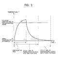
- Fig. 3 shows the relationship between the temperature T and the energization time t when the electrical power applied to the heating elements is low.
- the applied electrical power is low, the amount of heat generated by the heating elements 4 is small, so that the energization time t required for the temperature of each of the heating elements 4 to reach the recording allowing temperature is long. Since the energization time t cycle is long in addition to the amount of heat generated by the heating elements 4 being small, in the case where the energization process is divided into two portions, by the time the next energization of the heating elements 4 is carried out, the temperature of each of the heating elements 4 is reduced to about the temperature T that each of them had when the energization of the heating elements 4 was started.
- the temperature T of the heating elements 4 when they are subjected to the next energization process is such as not to differ greatly from the corresponding temperature where the energization process is divided into two portions.
- correction factors used for correcting the temperature loss caused by dividing the energization process differ depending upon the number of divisions of the energization process and in accordance with high and low applied electrical power values.
- the correction factors f are shown in the graph illustrated in Fig. 5.
- each of the heating elements 4, disposed at the line thermal head 2 is subjected to a divided energization process.
- the energization time t is determined using the correction table 10 which stores the correction factors, previously calculated using the exponential function where temperature T serves as a variable, and the energization times t corresponding to the correction factors.
- the method of obtaining the energization time t is not limited thereto. It may be obtained by successively calculating the correction factor by the previously provided exponential functional formula, and obtaining the energization time t that is in correspondence with the computed correction factor.
- each part of the line thermal printer 1 is similar to that of the conventional line thermal printer, so that a detailed description thereof will not be given below.
- the line thermal head 2 is brought into contact with the platen roller 3 through a thermosensible paper.
- the plurality of heating elements 4 of the line thermal head 2 are energized. Based on the recording information, the heating elements 4 are selectively driven so as to generate heat in order to cause the thermosensible paper to get colored, thereby making it possible to record a desired image or the like.
- the temperature of each of the heating elements 4 is measured by the temperature measuring means 5, and the information regarding the measured temperature T of each of the heating elements 4 is sent to the memory 9, disposed in the controlling means 7. Then, using the correction factor table 10, stored in the memory 9, the energization time t corresponding to the temperature T of each of the heating elements 4, measured by the temperature measuring means 5, is determined, and the information concerning the determined energization time t is sent to the driving motor through the CPU 8.
- the driving motor 6 causes each of the heating elements 4 to be subjected to a divided energization process and to be driven. In addition, it is controlled so that, based on the desired recording information, the heating elements are selectively made to produce heat for driving.
- the energization time t required for the temperature of each of the heating elements 4 to reach the recording allowing temperature can be easily determined in accordance with the number of divisions of the energization process, and, unlike the conventional method of correcting the temperature of each of the heating elements 4 using a linear functional formula, proper temperature corrections can be carried out.
- the present invention is effective in making it possible to record a proper image or the like on a thermosensible paper.
- the correction factor is obtained from the correction factor table 10 which stores the correction values previously computed by the previously provided exponential functional formula, it is not necessary to compute the correction factor using the exponential functional formula during the controlling operation, thereby making it possible to quickly provide the energization time t that is in correspondence with the correction factor at the controlling means 7.
- the recording is described as being carried out using a thermosensible paper as a recording medium
- the recording may be carried out by transferring the ink of an ink film, such as an ink sheet or an ink ribbon, onto an ordinary sheet.
- the line thermal printer of the present invention comprises controlling means for performing a controlling operation so that the energization of the heating elements is carried out in accordance with an energization time that has been obtained based on a correction factor that has been computed using an exponential functional formula previously provided based on a measured temperature of each of the heating elements. Therefore, it is not necessary to confirm and to provide a correction factor in accordance with the number of divisions of the energization process and high and low applied electrical power values, so that it is not troublesome to provide the correction factor.
- the present invention is effective in that a more accurate correction factor can be provided than that computed using a linear functional formula. This makes it possible to record a proper image or the like on the recording medium.
- Another line thermal printer of the present invention comprises controlling means, including a correction factor table which stores correction factors that have been previously computed using a previously provided exponential functional formula, for performing a controlling operation so that the energization of the heating elements is carried out in accordance with an energization time that has been obtained by a correction factor corresponding to a measured temperature of each of the heating elements, obtained from the correction factor table. Therefore, it is no longer necessary to provide time for calculating the correction factor using the exponential functional formula at the controlling means. Therefore, it is possible to easily and properly provide the correction factor, and to quickly provide the correction factor at the controlling means. Consequently, it is possible to properly and quickly record an image or the like on a recording medium.
- controlling means including a correction factor table which stores correction factors that have been previously computed using a previously provided exponential functional formula, for performing a controlling operation so that the energization of the heating elements is carried out in accordance with an energization time that has been obtained by a correction factor corresponding to a measured temperature of each of the
- a method of controlling the energization of a line thermal printer of the present invention is such that a temperature of each of the heating elements is measured, a correction factor is computed using an exponential functional formula that has been previously provided based on the measured temperature of each of the heating elements, and an energization time is determined based on the computed correction factor in order to subject the heating elements to the divided energization process in accordance with the determined energization time. Therefore, it is not necessary to confirm and to provide a correction factor in accordance with the number of divisions of the energization process and high and low applied electrical power values, so that it is not troublesome to provide the correction factor.
- the present invention is effective in that a more accurate correction factor can be provided than that computed using a linear functional formula. This makes it possible to record a proper image or the like on the recording medium.
- Another method of controlling the energization of a line thermal printer of the present invention is such that a temperature of each of the heating elements is measured, the measured temperature of each of the heating elements and a correction factor that corresponds to the measured temperature of each of the heating elements are obtained from a correction factor table which stores the correction factors that have been previously computed by a previously provided exponential functional formula, and an energization time that corresponds to the obtained correction factor is determined in order to subject the heating elements to the divided energization process for a length of time equal to the determined energization time. Therefore, it is no longer necessary to provide time for calculating the correction factor using the exponential functional formula during the controlling operation. Therefore, it is possible to easily and properly provide the correction factor, and to quickly provide the correction factor during the controlling operation. Consequently, it is possible to properly and quickly record an image or the like on a recording medium.
Landscapes
- Electronic Switches (AREA)
- Heat Sensitive Colour Forming Recording (AREA)
Abstract
Description
- The present invention relates to a line thermal printer and an energization controlling method thereof. More particularly, the present invention relates to a line thermal printer which makes it possible to perform a controlling operation so that a divided energization process is carried out by easily and properly correcting the temperature loss of heating elements caused by dividing the time of energization with respect to each of the heating elements; and an energization controlling method thereof.
- Hitherto, there has been known a line thermal printer in which a line thermal head with a length allowing it to oppose the range of printing of a recording medium in a widthwise direction thereof is brought into contact with a platen roller through the recording medium, and, while, in this state of contact, the recording medium is transported as a result of rotationally driving the platen roller, a plurality of heating elements of the line thermal head are selectively driven based on recording information, and generate heat, thereby recording a desired image or the like. The line thermal printer carries out a recording operation by, for example, using a thermosensible paper as a recording medium, and applying heat to the thermosensible paper, or using an ink film, such as an ink ribbon or an ink sheet, and applying heat to the ink film in order to transfer the ink of the ink film onto a recording medium.
- The line thermal head of this type of line thermal printer comprises a very large number of heating elements arranged in rows in a direction perpendicular to the direction in which the recording medium is transported. Therefore, when all of the heating elements are energized and driven at the same time, a large drive circuit is required. As a result, the supply power becomes large, so that the heating elements cannot be driven using a battery.
- For this reason, there has hitherto been used an energization controlling method which makes it possible to reduce the size of the driving circuit and to drive the heating elements using a battery with a small capacity by energizing every several number of heating elements by dividing the energization process in order to reduce the number of heating elements that are energized at the same time, thereby reducing the amount of applied electrical power.
- In the line thermal printer using this type of energization controlling method used to divide the energization process, when a recording operation is being performed on a recording medium, there are times when the heating elements are energized and times when they are not energized. Therefore, when they are not being energized, the heat that has been generated due to the energization of the heating elements that has been previously carried out is radiated, thereby reducing the temperature of the heating elements that are not being energized. In order to decrease the size of the driving circuit and to decrease the amount of applied electrical power, the number of divisions of the energization process with respect to the heating elements must be increased to a certain extent. However, increasing the number of divisions of the energization process with respect to the heating elements causes the time during which the heating elements are energized to be longer than the time during which they are not energized, so that the temperature of the heating elements is reduced even more. In this case, even when the thermal elements are subsequently energized, in performing a recording operation on a recording medium, the temperature may not rise high enough to a recording allowing temperature in order for the heating elements to cause a thermosensible paper to be colored or to cause the ink of an ink film to be transferred onto the recording medium. In that case, the problem that a proper image or the like cannot be recorded on the recording medium arises.
- Accordingly, in order for the temperature of each of the heating elements to reach a recording allowing temperature, and a proper recording operation to be performed on the recording medium, it has been necessary to correct the temperature of each of the heating elements.
- Here, in correcting the temperature of each of the heating elements, when the numbers of divisions of the energization process with respect to each of the heating elements are different, the times during which energization is not carried out differ, so that heat losses of the heating elements when the next energization of each of the heating elements is carried out differ. Therefore, the temperature of each of the heating elements must be corrected in accordance with the number of divisions of the energization process. Consequently, in correcting the temperatures of the heating elements that differ in accordance with the number of divisions of the energization process, either separate correction factors are provided or correction factors are calculated using a linear functional formula as illustrated in Fig. 6. Here, the correction factor is expressed in accordance with the number of divisions of the energization time required for the temperature of each of the thermal elements to reach the recording allowing temperature.
- However, providing separate correction factors that differ in accordance with the number of divisions of the energization process is troublesome because it requires confirmation of the correction factors in accordance with the number of divisions of the energization process.
- Through research, the applicant has found out that changes in the temperature of a heating element can be expressed by an exponential functional formula, so that the correction factor used for correcting the temperature loss of the heating element caused by dividing the energization process can be expressed by an exponential functional formula. Therefore, since, when a correction factor is calculated using a linear functional formula, an error occurs between the correction factor and the energization time required for the temperature of each of the heating elements to reach the recording allowing temperature, the problem that a proper recording operation cannot be carried out on a recording medium arises. In addition, in subjecting the heating elements to a divided energization process, the temperature of each of the heating elements and the energization time required for the temperature of each of the heating elements to reach the recording allowing temperature are different in accordance with high and low applied electrical power values. Therefore, since the temperature losses of the heating elements by the time the next energization process is carried out are different, separate correction factors also need to be provided in accordance with high and low applied electrical power values, making it troublesome to provide the correction factors.
- Accordingly, in view of the above-described problems, it is an object of the present invention to provide a line thermal printer which makes it possible to perform a controlling operation so that a divided energization process is carried out by easily and properly correcting the temperature losses of heating elements caused by dividing the energization process. It is another object of the present invention to provide an energization controlling method of the line thermal printer.
- To this end, according to a first aspect of the present invention, there is provided a line thermal printer in which a plurality of heating elements are disposed at a line thermal head, with the plurality of heating elements being subjected to a divided energization process in order to energize every several number of heating elements by dividing an energization process into a plurality of portions. The line thermal printer comprises controlling means for performing a controlling operation so that the energization of the heating elements is carried out in accordance with an energization time that has been obtained based on a correction factor that has been computed using an exponential functional formula previously provided based on a measured temperature of each of the heating elements.
- According to the first aspect, since the correction factor is calculated by the previously provided exponential functional formula, it is not necessary to confirm and to provide the correction factor in accordance with the number of divisions of the energization process and in accordance with high and low electrical power values, so that it is not troublesome to determine the correction factor. In addition, a more accurate correction factor can be determined compared to when the correction factor is computed using a linear functional formula.
- According to a second aspect of the present invention, there is provided a line thermal printer in which a plurality of heating elements are disposed at a line thermal head, with the plurality of heating elements being subjected to a divided energization process in order to energize every several number of heating elements by dividing an energization process into a plurality of portions. The line thermal printer comprises controlling means, including a correction factor table which stores correction factors that have been previously computed using a previously provided exponential functional formula, for performing a controlling operation so that the energization of the heating elements is carried out in accordance with an energization time that has been obtained by a correction factor corresponding to a measured temperature of each of the heating elements, obtained from the correction factor table.
- According to the second aspect, since the energization time is obtained from the correction factor table which stores the correction factors previously computed using the previously provided exponential functional formula, it is no longer necessary to provide time to compute the correction factor using the exponential functional formula at the controlling means. Therefore, it is possible to easily and properly provide the correction factor, and to quickly provide the correction factor at the controlling means.
- According to a third aspect of the present invention, there is provided a method of controlling an energization process in which a controlling operation is carried out so that a plurality of heating elements of a line thermal head are subjected to a divided energization process in order to energize every several number of heating elements by dividing the energization process into a plurality of portions. In the method, a temperature of each of the heating elements is measured, a correction factor is computed using an exponential functional formula that has been previously provided based on the measured temperature of each of the heating elements, and an energization time is determined based on the computed correction factor in order to subject the heating elements to the divided energization process in accordance with the determined energization time.
- According to the third aspect, since the correction factor is calculated by the previously provided exponential functional formula, it is not necessary to confirm and to provide the correction factor in accordance with the number of divisions of the energization process and in accordance with high and low electrical power values, so that it is not troublesome to determine the correction factor. In addition, a more accurate correction factor can be determined compared to when the correction factor is computed using a linear functional formula.
- According to a fourth aspect of the present invention, there is provided a method of controlling an energization process in which a controlling operation is carried out so that a plurality of heating elements of a line thermal head are subjected to a divided energization process in order to energize every several number of heating elements by dividing the energization process into a plurality of portions. In the method, a temperature of each of the heating elements is measured, the measured temperature of each of the heating elements and a correction factor that corresponds to the measured temperature of each of the heating elements are obtained from a correction factor table which stores the correction factors that have been previously computed by a previously provided exponential functional formula, and an energization time that corresponds to the obtained correction factor is determined in order to subject the heating elements to the divided energization process for a length of time equal to the determined energization time.
- According to the fourth aspect, since the energization time is obtained from the correction factor table that stores the correction factors that have been previously calculated using the previously provided exponential functional formula, it is no longer necessary to provide time for calculating the correction factor using the exponential functional formula when the controlling operation is carried out. Therefore, it is possible to easily and properly provide the correction factor, and to quickly provide the correction factor during the controlling operation.
- An embodiment of the present invention will now be described by way of example only, with reference to the accompanying diagrammatic drawings, in which:
- Fig. 1 illustrates a line thermal printer of the present invention.
- Fig. 2 is a graph showing the changes in temperature of heating elements when the applied electrical power is high.
- Fig. 3 is a graph showing the changes in temperature of the heating elements when the applied electrical power is low.
- Fig. 4 is a graph showing the differences in the times of energization of the heating elements for high and low applied electrical power values.
- Fig. 5 is a graph showing the correction factor in accordance with the number of divisions of the energization process.
- Fig. 6 is a graph showing the correction factor in accordance with the number of divisions of the energization process in a conventional example.
-
- Hereunder, a description of a preferred embodiment of the present invention will be given with reference to Figs. 1 to 5.
- Fig. 1 illustrates an embodiment of a line thermal printer in accordance with the present invention. In a line
thermal printer 1, a linethermal head 2 is disposed so as to oppose aplaten roller 3. The linethermal head 2 has a length which allows it to oppose the range of printing of a thermosensible paper in a widthwise direction thereof. The linethermal head 2 comprises a plurality ofheating elements 4 that are disposed in rows in a direction which is perpendicular to the direction in which a recording medium is transported. Aspring 11 for press-contacting theheating elements 4 of the linethermal head 2 to a thermosensible paper is disposed at the surface of the linethermal head 2 opposite to the surface where theheating elements 4 of the linethermal head 2 are disposed. - A
driving motor 6 is mounted at the linethermal printer 1 in order to drive theplate roller 3 and a temperature measuring means 5, such as a thermistor, for measuring a temperature T of each of theheating elements 4. The temperature measuring means 5 and the drivingmotor 6 are electrically connected to a controllingmeans 7 for controlling the operation of each part of the linethermal printer 1. At least a CPU (central processing unit) 8 and a memory 9, such as a ROM or RAM, having the proper capacity are disposed in the controllingmeans 7. In the memory 9 is recorded at least a program used performing a controlling operation so that theheating elements 4 are driven by dividing the energization process with respect to each of the heating elements, so that theheating elements 4 are selectively made to generate heat based on recording information, and so that, for example, theplaten roller 3 is rotationally driven. - Here, when an energization time t with respect to each of the
heating elements 4 elapses, and energization of theheating elements 4 is no longer carried out, a temperature T of each of theheating elements 4 decreases. At this time, the temperature T of each of theheating elements 4 is:heating elements 4 can be expressed by an exponential function. In other words, a temperature change T(t) of each of theheating elements 4 is: - Fig. 2 shows the relationship between the temperature T and the energization time t when the electrical power applied to the
heating elements 4 is high. When the applied electrical power is high, the amount of heat generated by theheating elements 4 is high, so the energization time t required for the temperature of each of theheating elements 4 to reach the recording allowing temperature is short. Since the energization time t cycle is short in addition to the amount of heat generated by theheating elements 4 being large, when the energization process is divided into two portions, the temperature T of each of theheating elements 4 is not reduced very much by the time the next energization process of theheating elements 4. In contrast, in the case where the energization process is divided into four portions, by the time the next energization of theheating elements 4 is carried out, the temperature T of each of theheating elements 4 is reduced to about the same temperature as that when the energization of theheating elements 4 was started. Therefore, there is a large difference between the temperatures T of theheating elements 4 for the cases where the energization process is divided into two portions and where it is divided into four portions. - Fig. 3 shows the relationship between the temperature T and the energization time t when the electrical power applied to the heating elements is low. When the applied electrical power is low, the amount of heat generated by the
heating elements 4 is small, so that the energization time t required for the temperature of each of theheating elements 4 to reach the recording allowing temperature is long. Since the energization time t cycle is long in addition to the amount of heat generated by theheating elements 4 being small, in the case where the energization process is divided into two portions, by the time the next energization of theheating elements 4 is carried out, the temperature of each of theheating elements 4 is reduced to about the temperature T that each of them had when the energization of theheating elements 4 was started. In the case where the energization process is divided into four portions, the temperature T of theheating elements 4 when they are subjected to the next energization process is such as not to differ greatly from the corresponding temperature where the energization process is divided into two portions. - Comparing the cases where the applied electrical power is high and where it is low, as shown in Fig. 4, a difference occurs between the energization times required for the temperatures of the
heating elements 4 to reach the recording allowing temperature. Therefore, a large difference occurs between the lengths of the energization time cycles when the energization process is divided. - Therefore, the correction factors used for correcting the temperature loss caused by dividing the energization process differ depending upon the number of divisions of the energization process and in accordance with high and low applied electrical power values. A correction factor f in accordance with each number of divisions of the energization process can be expressed by the following exponential functional formula:
- Accordingly, there is stored a program used for a controlling operation carried out so that the correction factor based on the temperature T, measured by the temperature measuring means 5, is obtained from the correction factor table 10, and the energization time t in accordance with the obtained correction factor is determined in order to energize each of the
heating elements 4. - Then, based on the information sent from the controlling means 7, the driving
motor 5 is driven, and, based on the energization time t corresponding to the correction factor, each of theheating elements 4, disposed at the linethermal head 2, is subjected to a divided energization process. - In the embodiment, the energization time t is determined using the correction table 10 which stores the correction factors, previously calculated using the exponential function where temperature T serves as a variable, and the energization times t corresponding to the correction factors. However, the method of obtaining the energization time t is not limited thereto. It may be obtained by successively calculating the correction factor by the previously provided exponential functional formula, and obtaining the energization time t that is in correspondence with the computed correction factor.
- The structure of each part of the line
thermal printer 1 is similar to that of the conventional line thermal printer, so that a detailed description thereof will not be given below. - A description of the method of controlling the energization of the line thermal printer of the present invention will now be given.
- In the line
thermal printer 1 of the embodiment, the linethermal head 2 is brought into contact with theplaten roller 3 through a thermosensible paper. In this state of contact, while theplaten roller 3 is rotationally driven and the thermosensible paper is transported, the plurality ofheating elements 4 of the linethermal head 2 are energized. Based on the recording information, theheating elements 4 are selectively driven so as to generate heat in order to cause the thermosensible paper to get colored, thereby making it possible to record a desired image or the like. - In the method of controlling the energization with respect to each of the
heating elements 4 of the embodiment of the present invention, in order to correct the temperature T which has been lost by dividing the energization process, when the recording information is sent to theCPU 8, disposed in the controlling means 7, the temperature of each of theheating elements 4 is measured by the temperature measuring means 5, and the information regarding the measured temperature T of each of theheating elements 4 is sent to the memory 9, disposed in the controlling means 7. Then, using the correction factor table 10, stored in the memory 9, the energization time t corresponding to the temperature T of each of theheating elements 4, measured by the temperature measuring means 5, is determined, and the information concerning the determined energization time t is sent to the driving motor through theCPU 8. Based on this information, while the thermosensible paper is transported by rotationally driving theplaten roller 3, the drivingmotor 6 causes each of theheating elements 4 to be subjected to a divided energization process and to be driven. In addition, it is controlled so that, based on the desired recording information, the heating elements are selectively made to produce heat for driving. - Accordingly, in the embodiment, by computing the correction value using the previously provided exponential functional formula, the energization time t required for the temperature of each of the
heating elements 4 to reach the recording allowing temperature can be easily determined in accordance with the number of divisions of the energization process, and, unlike the conventional method of correcting the temperature of each of theheating elements 4 using a linear functional formula, proper temperature corrections can be carried out. As a result, the present invention is effective in making it possible to record a proper image or the like on a thermosensible paper. In addition, since the correction factor is obtained from the correction factor table 10 which stores the correction values previously computed by the previously provided exponential functional formula, it is not necessary to compute the correction factor using the exponential functional formula during the controlling operation, thereby making it possible to quickly provide the energization time t that is in correspondence with the correction factor at the controlling means 7. - The present invention is not limited to the above-described embodiment, so that various modifications can be made as necessary.
- For example, although, in the above-described embodiment, the recording is described as being carried out using a thermosensible paper as a recording medium, the recording may be carried out by transferring the ink of an ink film, such as an ink sheet or an ink ribbon, onto an ordinary sheet.
- As can be understood from the foregoing description, the line thermal printer of the present invention comprises controlling means for performing a controlling operation so that the energization of the heating elements is carried out in accordance with an energization time that has been obtained based on a correction factor that has been computed using an exponential functional formula previously provided based on a measured temperature of each of the heating elements. Therefore, it is not necessary to confirm and to provide a correction factor in accordance with the number of divisions of the energization process and high and low applied electrical power values, so that it is not troublesome to provide the correction factor. In addition, the present invention is effective in that a more accurate correction factor can be provided than that computed using a linear functional formula. This makes it possible to record a proper image or the like on the recording medium.
- Another line thermal printer of the present invention comprises controlling means, including a correction factor table which stores correction factors that have been previously computed using a previously provided exponential functional formula, for performing a controlling operation so that the energization of the heating elements is carried out in accordance with an energization time that has been obtained by a correction factor corresponding to a measured temperature of each of the heating elements, obtained from the correction factor table. Therefore, it is no longer necessary to provide time for calculating the correction factor using the exponential functional formula at the controlling means. Therefore, it is possible to easily and properly provide the correction factor, and to quickly provide the correction factor at the controlling means. Consequently, it is possible to properly and quickly record an image or the like on a recording medium.
- A method of controlling the energization of a line thermal printer of the present invention is such that a temperature of each of the heating elements is measured, a correction factor is computed using an exponential functional formula that has been previously provided based on the measured temperature of each of the heating elements, and an energization time is determined based on the computed correction factor in order to subject the heating elements to the divided energization process in accordance with the determined energization time. Therefore, it is not necessary to confirm and to provide a correction factor in accordance with the number of divisions of the energization process and high and low applied electrical power values, so that it is not troublesome to provide the correction factor. In addition, the present invention is effective in that a more accurate correction factor can be provided than that computed using a linear functional formula. This makes it possible to record a proper image or the like on the recording medium.
- Another method of controlling the energization of a line thermal printer of the present invention is such that a temperature of each of the heating elements is measured, the measured temperature of each of the heating elements and a correction factor that corresponds to the measured temperature of each of the heating elements are obtained from a correction factor table which stores the correction factors that have been previously computed by a previously provided exponential functional formula, and an energization time that corresponds to the obtained correction factor is determined in order to subject the heating elements to the divided energization process for a length of time equal to the determined energization time. Therefore, it is no longer necessary to provide time for calculating the correction factor using the exponential functional formula during the controlling operation. Therefore, it is possible to easily and properly provide the correction factor, and to quickly provide the correction factor during the controlling operation. Consequently, it is possible to properly and quickly record an image or the like on a recording medium.
Claims (4)
- A line thermal printer in which a plurality of heating elements are disposed at a line thermal head, with the plurality of heating elements being subjected to a divided energization process in order to energize every several number of heating elements by dividing an energization process into a plurality of portions, the line thermal printer comprising:
controlling means for performing a controlling operation so that the energization of the heating elements is carried out in accordance with an energization time that has been obtained based on a correction factor that has been computed using an exponential functional formula previously provided based on a measured temperature of each of the heating elements. - A line thermal printer in which a plurality of heating elements are disposed at a line thermal head, with the plurality of heating elements being subjected to a divided energization process in order to energize every several number of heating elements by dividing an energization process into a plurality of portions, the line thermal printer comprising:
controlling means, including a correction factor table which stores correction factors that have been previously computed using a previously provided exponential functional formula, for performing a controlling operation so that the energization of the heating elements is carried out in accordance with an energization time that has been obtained by a correction factor corresponding to a measured temperature of each of the heating elements, obtained from the correction factor table. - A method of controlling an energization process of a line printer in which a controlling operation is carried out so that a plurality of heating elements of a line thermal head are subjected to a divided energization process in order to energize every several number of heating elements by dividing the energization process into a plurality of portions, wherein:
a temperature of each of the heating elements is measured, a correction factor is computed using an exponential functional formula that has been previously provided based on the measured temperature of each of the heating elements, and an energization time is determined based on the computed correction factor in order to subject the heating elements to the divided energization process in accordance with the determined energization time. - A method of controlling an energization process of a line thermal printer in which a controlling operation is carried out so that a plurality of heating elements of a line thermal head are subjected to a divided energization process in order to energize every several number of heating elements by dividing the energization process into a plurality of portions, wherein:
a temperature of each of the heating elements is measured, the measured temperature of each of the heating elements and a correction factor that corresponds to the measured temperature of each of the heating elements are obtained from a correction factor table which stores the correction factors that have been previously computed by a previously provided exponential functional formula, and an energization time that corresponds to the obtained correction factor is determined in order to subject the heating elements to the divided energization process for a length of time equal to the determined energization time.
Applications Claiming Priority (2)
| Application Number | Priority Date | Filing Date | Title |
|---|---|---|---|
| JP2000191000A JP2002002011A (en) | 2000-06-26 | 2000-06-26 | Line printer and its electrification control method |
| JP2000191000 | 2000-06-26 |
Publications (2)
| Publication Number | Publication Date |
|---|---|
| EP1167047A1 true EP1167047A1 (en) | 2002-01-02 |
| EP1167047B1 EP1167047B1 (en) | 2005-11-23 |
Family
ID=18690374
Family Applications (1)
| Application Number | Title | Priority Date | Filing Date |
|---|---|---|---|
| EP01305187A Expired - Lifetime EP1167047B1 (en) | 2000-06-26 | 2001-06-14 | Line thermal printer and energization controlling method |
Country Status (9)
| Country | Link |
|---|---|
| US (1) | US6597386B2 (en) |
| EP (1) | EP1167047B1 (en) |
| JP (1) | JP2002002011A (en) |
| KR (1) | KR100378388B1 (en) |
| CN (1) | CN1173831C (en) |
| AT (1) | ATE310642T1 (en) |
| DE (1) | DE60115152T2 (en) |
| ES (1) | ES2248243T3 (en) |
| TW (1) | TW495446B (en) |
Families Citing this family (6)
| Publication number | Priority date | Publication date | Assignee | Title |
|---|---|---|---|---|
| US6815923B2 (en) * | 2002-08-08 | 2004-11-09 | Spielo Manufacturing Incorporated | Stepper motor jam detection circuit |
| JP4062294B2 (en) * | 2004-09-21 | 2008-03-19 | ソニー株式会社 | Printing apparatus and printing method |
| EP2371558B1 (en) * | 2010-03-31 | 2015-04-15 | Brother Kogyo Kabushiki Kaisha | Thermal printer |
| CN102501641B (en) * | 2011-10-10 | 2014-10-01 | 深圳市理邦精密仪器股份有限公司 | Device and method for controlling heating time of thermosensitive head |
| EP3339041B1 (en) * | 2015-08-21 | 2020-03-18 | Sato Holdings Kabushiki Kaisha | Printer |
| US12370809B2 (en) * | 2023-09-20 | 2025-07-29 | Toshiba Tec Kabushiki Kaisha | Printer |
Citations (5)
| Publication number | Priority date | Publication date | Assignee | Title |
|---|---|---|---|---|
| JPS5725977A (en) * | 1980-07-24 | 1982-02-10 | Omron Tateisi Electronics Co | Controlling method of heating in heat-sensitive type printer |
| US4887092A (en) * | 1987-12-07 | 1989-12-12 | Siemens Aktiengesellschaft | Thermal printing method |
| US5339099A (en) * | 1990-03-16 | 1994-08-16 | Seiko Instruments Inc. | Line thermal printer having driving pulses of variable pulse width |
| EP0716927A2 (en) * | 1994-12-16 | 1996-06-19 | Nec Corporation | Thermal head apparatus |
| US5623297A (en) * | 1993-07-07 | 1997-04-22 | Intermec Corporation | Method and apparatus for controlling a thermal printhead |
Family Cites Families (5)
| Publication number | Priority date | Publication date | Assignee | Title |
|---|---|---|---|---|
| EP0368323B1 (en) * | 1988-11-09 | 1999-05-26 | Canon Kabushiki Kaisha | Thermal transfer recording apparatus and facsimile apparatus |
| US5608333A (en) * | 1993-06-18 | 1997-03-04 | Fuji Photo Film Co., Ltd. | Method of driving heating element to match its resistance, thermal printer, and resistance measuring device |
| US5548688A (en) * | 1993-12-23 | 1996-08-20 | Intermec Corporation | Method of data handling and activating thermal print elements in a thermal printhead |
| JPH0890818A (en) | 1994-09-21 | 1996-04-09 | Kofu Nippon Denki Kk | Line thermal printer |
| JPH0890821A (en) | 1994-09-22 | 1996-04-09 | Kofu Nippon Denki Kk | Drive controller for thermal printer |
-
2000
- 2000-06-26 JP JP2000191000A patent/JP2002002011A/en active Pending
-
2001
- 2001-05-23 TW TW090112394A patent/TW495446B/en not_active IP Right Cessation
- 2001-06-14 EP EP01305187A patent/EP1167047B1/en not_active Expired - Lifetime
- 2001-06-14 AT AT01305187T patent/ATE310642T1/en not_active IP Right Cessation
- 2001-06-14 DE DE60115152T patent/DE60115152T2/en not_active Expired - Lifetime
- 2001-06-14 ES ES01305187T patent/ES2248243T3/en not_active Expired - Lifetime
- 2001-06-25 US US09/888,900 patent/US6597386B2/en not_active Expired - Fee Related
- 2001-06-25 KR KR10-2001-0036235A patent/KR100378388B1/en not_active Expired - Fee Related
- 2001-06-25 CN CNB011296259A patent/CN1173831C/en not_active Expired - Fee Related
Patent Citations (5)
| Publication number | Priority date | Publication date | Assignee | Title |
|---|---|---|---|---|
| JPS5725977A (en) * | 1980-07-24 | 1982-02-10 | Omron Tateisi Electronics Co | Controlling method of heating in heat-sensitive type printer |
| US4887092A (en) * | 1987-12-07 | 1989-12-12 | Siemens Aktiengesellschaft | Thermal printing method |
| US5339099A (en) * | 1990-03-16 | 1994-08-16 | Seiko Instruments Inc. | Line thermal printer having driving pulses of variable pulse width |
| US5623297A (en) * | 1993-07-07 | 1997-04-22 | Intermec Corporation | Method and apparatus for controlling a thermal printhead |
| EP0716927A2 (en) * | 1994-12-16 | 1996-06-19 | Nec Corporation | Thermal head apparatus |
Non-Patent Citations (1)
| Title |
|---|
| PATENT ABSTRACTS OF JAPAN vol. 006, no. 089 (M - 132) 27 May 1982 (1982-05-27) * |
Also Published As
| Publication number | Publication date |
|---|---|
| KR100378388B1 (en) | 2003-03-29 |
| TW495446B (en) | 2002-07-21 |
| ATE310642T1 (en) | 2005-12-15 |
| EP1167047B1 (en) | 2005-11-23 |
| DE60115152D1 (en) | 2005-12-29 |
| KR20020001586A (en) | 2002-01-09 |
| CN1173831C (en) | 2004-11-03 |
| US20010055057A1 (en) | 2001-12-27 |
| US6597386B2 (en) | 2003-07-22 |
| CN1329991A (en) | 2002-01-09 |
| ES2248243T3 (en) | 2006-03-16 |
| DE60115152T2 (en) | 2006-08-03 |
| JP2002002011A (en) | 2002-01-08 |
Similar Documents
| Publication | Publication Date | Title |
|---|---|---|
| US4827279A (en) | Process for correcting across-the-head nonuniformity in thermal printers | |
| JP2627348B2 (en) | Line thermal printer | |
| US7830404B2 (en) | Printer and control method thereof | |
| US5841461A (en) | Accumulated heat correction method and apparatus | |
| US6597386B2 (en) | Line thermal printer and energization controlling method | |
| US5204704A (en) | Thermal transfer printer and method of controlling print density in thermal transfer printing using the same | |
| EP3230798A1 (en) | Temperature control for an imaging laser | |
| JP2945434B2 (en) | LED printer | |
| JP2020071325A (en) | Fixing device and image forming apparatus | |
| JP3362448B2 (en) | Printing device | |
| JP2002002010A (en) | Thermal printer | |
| JP2005262814A (en) | Thermal head apparatus | |
| JP2009274410A (en) | Thermal head and thermal transfer printer | |
| JPS63125356A (en) | Thermal printer | |
| JPS6228264A (en) | Multi-value driving system for thermal head | |
| JP5007408B2 (en) | Printer and control method thereof | |
| JPH0890818A (en) | Line thermal printer | |
| JPH04323067A (en) | Print gap adjustment device in printer | |
| JP2025039988A (en) | Thermal printer and method for controlling the same | |
| JP2001253106A (en) | Thermal printer and thermal head control method | |
| JPS6230062A (en) | thermal printer | |
| JPS63178063A (en) | Thermal recording apparatus | |
| JPH04320859A (en) | Thermal printer | |
| JP2000280510A (en) | Method for correcting density irregularity of thermal printer and thermal printer | |
| JPH04187465A (en) | Printer |
Legal Events
| Date | Code | Title | Description |
|---|---|---|---|
| PUAI | Public reference made under article 153(3) epc to a published international application that has entered the european phase |
Free format text: ORIGINAL CODE: 0009012 |
|
| AK | Designated contracting states |
Kind code of ref document: A1 Designated state(s): AT BE CH CY DE DK ES FI FR GB GR IE IT LI LU MC NL PT SE TR |
|
| AX | Request for extension of the european patent |
Free format text: AL;LT;LV;MK;RO;SI |
|
| 17P | Request for examination filed |
Effective date: 20020105 |
|
| AKX | Designation fees paid |
Free format text: AT BE CH CY DE DK ES FI FR GB GR IE IT LI LU MC NL PT SE TR |
|
| 17Q | First examination report despatched |
Effective date: 20040422 |
|
| GRAP | Despatch of communication of intention to grant a patent |
Free format text: ORIGINAL CODE: EPIDOSNIGR1 |
|
| GRAS | Grant fee paid |
Free format text: ORIGINAL CODE: EPIDOSNIGR3 |
|
| GRAA | (expected) grant |
Free format text: ORIGINAL CODE: 0009210 |
|
| AK | Designated contracting states |
Kind code of ref document: B1 Designated state(s): AT BE CH CY DE DK ES FI FR GB GR IE IT LI LU MC NL PT SE TR |
|
| PG25 | Lapsed in a contracting state [announced via postgrant information from national office to epo] |
Ref country code: BE Free format text: LAPSE BECAUSE OF FAILURE TO SUBMIT A TRANSLATION OF THE DESCRIPTION OR TO PAY THE FEE WITHIN THE PRESCRIBED TIME-LIMIT Effective date: 20051123 Ref country code: AT Free format text: LAPSE BECAUSE OF FAILURE TO SUBMIT A TRANSLATION OF THE DESCRIPTION OR TO PAY THE FEE WITHIN THE PRESCRIBED TIME-LIMIT Effective date: 20051123 Ref country code: FI Free format text: LAPSE BECAUSE OF FAILURE TO SUBMIT A TRANSLATION OF THE DESCRIPTION OR TO PAY THE FEE WITHIN THE PRESCRIBED TIME-LIMIT Effective date: 20051123 |
|
| REG | Reference to a national code |
Ref country code: GB Ref legal event code: FG4D |
|
| REG | Reference to a national code |
Ref country code: CH Ref legal event code: EP |
|
| REF | Corresponds to: |
Ref document number: 60115152 Country of ref document: DE Date of ref document: 20051229 Kind code of ref document: P |
|
| REG | Reference to a national code |
Ref country code: IE Ref legal event code: FG4D |
|
| PG25 | Lapsed in a contracting state [announced via postgrant information from national office to epo] |
Ref country code: GR Free format text: LAPSE BECAUSE OF FAILURE TO SUBMIT A TRANSLATION OF THE DESCRIPTION OR TO PAY THE FEE WITHIN THE PRESCRIBED TIME-LIMIT Effective date: 20060223 Ref country code: DK Free format text: LAPSE BECAUSE OF FAILURE TO SUBMIT A TRANSLATION OF THE DESCRIPTION OR TO PAY THE FEE WITHIN THE PRESCRIBED TIME-LIMIT Effective date: 20060223 |
|
| REG | Reference to a national code |
Ref country code: SE Ref legal event code: TRGR |
|
| REG | Reference to a national code |
Ref country code: CH Ref legal event code: NV Representative=s name: BOGENSBERGER PATENT- & MARKENBUERO DR. BURKHARD BO |
|
| REG | Reference to a national code |
Ref country code: ES Ref legal event code: FG2A Ref document number: 2248243 Country of ref document: ES Kind code of ref document: T3 |
|
| PG25 | Lapsed in a contracting state [announced via postgrant information from national office to epo] |
Ref country code: PT Free format text: LAPSE BECAUSE OF FAILURE TO SUBMIT A TRANSLATION OF THE DESCRIPTION OR TO PAY THE FEE WITHIN THE PRESCRIBED TIME-LIMIT Effective date: 20060424 |
|
| PG25 | Lapsed in a contracting state [announced via postgrant information from national office to epo] |
Ref country code: IE Free format text: LAPSE BECAUSE OF NON-PAYMENT OF DUE FEES Effective date: 20060614 |
|
| PG25 | Lapsed in a contracting state [announced via postgrant information from national office to epo] |
Ref country code: MC Free format text: LAPSE BECAUSE OF NON-PAYMENT OF DUE FEES Effective date: 20060630 |
|
| ET | Fr: translation filed | ||
| PLBE | No opposition filed within time limit |
Free format text: ORIGINAL CODE: 0009261 |
|
| STAA | Information on the status of an ep patent application or granted ep patent |
Free format text: STATUS: NO OPPOSITION FILED WITHIN TIME LIMIT |
|
| 26N | No opposition filed |
Effective date: 20060824 |
|
| REG | Reference to a national code |
Ref country code: IE Ref legal event code: MM4A |
|
| PG25 | Lapsed in a contracting state [announced via postgrant information from national office to epo] |
Ref country code: LU Free format text: LAPSE BECAUSE OF NON-PAYMENT OF DUE FEES Effective date: 20060614 Ref country code: TR Free format text: LAPSE BECAUSE OF FAILURE TO SUBMIT A TRANSLATION OF THE DESCRIPTION OR TO PAY THE FEE WITHIN THE PRESCRIBED TIME-LIMIT Effective date: 20051123 |
|
| REG | Reference to a national code |
Ref country code: CH Ref legal event code: PFA Owner name: ALPS ELECTRIC CO., LTD. Free format text: ALPS ELECTRIC CO., LTD.#1-7 YUKIGAYA OTSUKA-CHO#OTA-KU TOKYO 145 (JP) -TRANSFER TO- ALPS ELECTRIC CO., LTD.#1-7 YUKIGAYA OTSUKA-CHO#OTA-KU TOKYO 145 (JP) |
|
| PG25 | Lapsed in a contracting state [announced via postgrant information from national office to epo] |
Ref country code: CY Free format text: LAPSE BECAUSE OF FAILURE TO SUBMIT A TRANSLATION OF THE DESCRIPTION OR TO PAY THE FEE WITHIN THE PRESCRIBED TIME-LIMIT Effective date: 20051123 |
|
| PGFP | Annual fee paid to national office [announced via postgrant information from national office to epo] |
Ref country code: ES Payment date: 20090623 Year of fee payment: 9 Ref country code: NL Payment date: 20090611 Year of fee payment: 9 |
|
| PGFP | Annual fee paid to national office [announced via postgrant information from national office to epo] |
Ref country code: FR Payment date: 20090605 Year of fee payment: 9 Ref country code: IT Payment date: 20090623 Year of fee payment: 9 Ref country code: SE Payment date: 20090605 Year of fee payment: 9 |
|
| PGFP | Annual fee paid to national office [announced via postgrant information from national office to epo] |
Ref country code: CH Payment date: 20090430 Year of fee payment: 9 |
|
| REG | Reference to a national code |
Ref country code: NL Ref legal event code: V1 Effective date: 20110101 |
|
| REG | Reference to a national code |
Ref country code: CH Ref legal event code: PL |
|
| EUG | Se: european patent has lapsed | ||
| REG | Reference to a national code |
Ref country code: FR Ref legal event code: ST Effective date: 20110228 |
|
| PG25 | Lapsed in a contracting state [announced via postgrant information from national office to epo] |
Ref country code: IT Free format text: LAPSE BECAUSE OF NON-PAYMENT OF DUE FEES Effective date: 20100614 |
|
| PG25 | Lapsed in a contracting state [announced via postgrant information from national office to epo] |
Ref country code: LI Free format text: LAPSE BECAUSE OF NON-PAYMENT OF DUE FEES Effective date: 20100630 Ref country code: CH Free format text: LAPSE BECAUSE OF NON-PAYMENT OF DUE FEES Effective date: 20100630 |
|
| PG25 | Lapsed in a contracting state [announced via postgrant information from national office to epo] |
Ref country code: FR Free format text: LAPSE BECAUSE OF NON-PAYMENT OF DUE FEES Effective date: 20100630 Ref country code: NL Free format text: LAPSE BECAUSE OF NON-PAYMENT OF DUE FEES Effective date: 20110101 |
|
| REG | Reference to a national code |
Ref country code: ES Ref legal event code: FD2A Effective date: 20110714 |
|
| PG25 | Lapsed in a contracting state [announced via postgrant information from national office to epo] |
Ref country code: ES Free format text: LAPSE BECAUSE OF NON-PAYMENT OF DUE FEES Effective date: 20110704 |
|
| PGFP | Annual fee paid to national office [announced via postgrant information from national office to epo] |
Ref country code: GB Payment date: 20110523 Year of fee payment: 11 |
|
| PG25 | Lapsed in a contracting state [announced via postgrant information from national office to epo] |
Ref country code: ES Free format text: LAPSE BECAUSE OF NON-PAYMENT OF DUE FEES Effective date: 20100615 |
|
| PGFP | Annual fee paid to national office [announced via postgrant information from national office to epo] |
Ref country code: DE Payment date: 20110630 Year of fee payment: 11 |
|
| PG25 | Lapsed in a contracting state [announced via postgrant information from national office to epo] |
Ref country code: SE Free format text: LAPSE BECAUSE OF NON-PAYMENT OF DUE FEES Effective date: 20100615 |
|
| GBPC | Gb: european patent ceased through non-payment of renewal fee |
Effective date: 20120614 |
|
| PG25 | Lapsed in a contracting state [announced via postgrant information from national office to epo] |
Ref country code: DE Free format text: LAPSE BECAUSE OF NON-PAYMENT OF DUE FEES Effective date: 20130101 Ref country code: GB Free format text: LAPSE BECAUSE OF NON-PAYMENT OF DUE FEES Effective date: 20120614 |
|
| REG | Reference to a national code |
Ref country code: DE Ref legal event code: R119 Ref document number: 60115152 Country of ref document: DE Effective date: 20130101 |