EP1167040A1 - Ink jet printer head and method for manufacturing the same - Google Patents
Ink jet printer head and method for manufacturing the same Download PDFInfo
- Publication number
- EP1167040A1 EP1167040A1 EP01305445A EP01305445A EP1167040A1 EP 1167040 A1 EP1167040 A1 EP 1167040A1 EP 01305445 A EP01305445 A EP 01305445A EP 01305445 A EP01305445 A EP 01305445A EP 1167040 A1 EP1167040 A1 EP 1167040A1
- Authority
- EP
- European Patent Office
- Prior art keywords
- ink
- jet printer
- printer head
- ink jet
- piezoelectric member
- Prior art date
- Legal status (The legal status is an assumption and is not a legal conclusion. Google has not performed a legal analysis and makes no representation as to the accuracy of the status listed.)
- Granted
Links
Images



Classifications
-
- B—PERFORMING OPERATIONS; TRANSPORTING
- B41—PRINTING; LINING MACHINES; TYPEWRITERS; STAMPS
- B41J—TYPEWRITERS; SELECTIVE PRINTING MECHANISMS, i.e. MECHANISMS PRINTING OTHERWISE THAN FROM A FORME; CORRECTION OF TYPOGRAPHICAL ERRORS
- B41J2/00—Typewriters or selective printing mechanisms characterised by the printing or marking process for which they are designed
- B41J2/005—Typewriters or selective printing mechanisms characterised by the printing or marking process for which they are designed characterised by bringing liquid or particles selectively into contact with a printing material
- B41J2/01—Ink jet
- B41J2/135—Nozzles
- B41J2/16—Production of nozzles
- B41J2/1621—Manufacturing processes
- B41J2/1623—Manufacturing processes bonding and adhesion
-
- B—PERFORMING OPERATIONS; TRANSPORTING
- B41—PRINTING; LINING MACHINES; TYPEWRITERS; STAMPS
- B41J—TYPEWRITERS; SELECTIVE PRINTING MECHANISMS, i.e. MECHANISMS PRINTING OTHERWISE THAN FROM A FORME; CORRECTION OF TYPOGRAPHICAL ERRORS
- B41J2/00—Typewriters or selective printing mechanisms characterised by the printing or marking process for which they are designed
- B41J2/005—Typewriters or selective printing mechanisms characterised by the printing or marking process for which they are designed characterised by bringing liquid or particles selectively into contact with a printing material
- B41J2/01—Ink jet
- B41J2/135—Nozzles
- B41J2/14—Structure thereof only for on-demand ink jet heads
- B41J2/14201—Structure of print heads with piezoelectric elements
- B41J2/14209—Structure of print heads with piezoelectric elements of finger type, chamber walls consisting integrally of piezoelectric material
-
- B—PERFORMING OPERATIONS; TRANSPORTING
- B41—PRINTING; LINING MACHINES; TYPEWRITERS; STAMPS
- B41J—TYPEWRITERS; SELECTIVE PRINTING MECHANISMS, i.e. MECHANISMS PRINTING OTHERWISE THAN FROM A FORME; CORRECTION OF TYPOGRAPHICAL ERRORS
- B41J2/00—Typewriters or selective printing mechanisms characterised by the printing or marking process for which they are designed
- B41J2/005—Typewriters or selective printing mechanisms characterised by the printing or marking process for which they are designed characterised by bringing liquid or particles selectively into contact with a printing material
- B41J2/01—Ink jet
- B41J2/135—Nozzles
- B41J2/16—Production of nozzles
- B41J2/1606—Coating the nozzle area or the ink chamber
-
- B—PERFORMING OPERATIONS; TRANSPORTING
- B41—PRINTING; LINING MACHINES; TYPEWRITERS; STAMPS
- B41J—TYPEWRITERS; SELECTIVE PRINTING MECHANISMS, i.e. MECHANISMS PRINTING OTHERWISE THAN FROM A FORME; CORRECTION OF TYPOGRAPHICAL ERRORS
- B41J2/00—Typewriters or selective printing mechanisms characterised by the printing or marking process for which they are designed
- B41J2/005—Typewriters or selective printing mechanisms characterised by the printing or marking process for which they are designed characterised by bringing liquid or particles selectively into contact with a printing material
- B41J2/01—Ink jet
- B41J2/135—Nozzles
- B41J2/16—Production of nozzles
- B41J2/1607—Production of print heads with piezoelectric elements
- B41J2/1609—Production of print heads with piezoelectric elements of finger type, chamber walls consisting integrally of piezoelectric material
-
- B—PERFORMING OPERATIONS; TRANSPORTING
- B41—PRINTING; LINING MACHINES; TYPEWRITERS; STAMPS
- B41J—TYPEWRITERS; SELECTIVE PRINTING MECHANISMS, i.e. MECHANISMS PRINTING OTHERWISE THAN FROM A FORME; CORRECTION OF TYPOGRAPHICAL ERRORS
- B41J2/00—Typewriters or selective printing mechanisms characterised by the printing or marking process for which they are designed
- B41J2/005—Typewriters or selective printing mechanisms characterised by the printing or marking process for which they are designed characterised by bringing liquid or particles selectively into contact with a printing material
- B41J2/01—Ink jet
- B41J2/135—Nozzles
- B41J2/16—Production of nozzles
- B41J2/1621—Manufacturing processes
- B41J2/1632—Manufacturing processes machining
-
- B—PERFORMING OPERATIONS; TRANSPORTING
- B41—PRINTING; LINING MACHINES; TYPEWRITERS; STAMPS
- B41J—TYPEWRITERS; SELECTIVE PRINTING MECHANISMS, i.e. MECHANISMS PRINTING OTHERWISE THAN FROM A FORME; CORRECTION OF TYPOGRAPHICAL ERRORS
- B41J2/00—Typewriters or selective printing mechanisms characterised by the printing or marking process for which they are designed
- B41J2/005—Typewriters or selective printing mechanisms characterised by the printing or marking process for which they are designed characterised by bringing liquid or particles selectively into contact with a printing material
- B41J2/01—Ink jet
- B41J2/135—Nozzles
- B41J2/16—Production of nozzles
- B41J2/1621—Manufacturing processes
- B41J2/164—Manufacturing processes thin film formation
- B41J2/1642—Manufacturing processes thin film formation thin film formation by CVD [chemical vapor deposition]
-
- B—PERFORMING OPERATIONS; TRANSPORTING
- B41—PRINTING; LINING MACHINES; TYPEWRITERS; STAMPS
- B41J—TYPEWRITERS; SELECTIVE PRINTING MECHANISMS, i.e. MECHANISMS PRINTING OTHERWISE THAN FROM A FORME; CORRECTION OF TYPOGRAPHICAL ERRORS
- B41J2/00—Typewriters or selective printing mechanisms characterised by the printing or marking process for which they are designed
- B41J2/005—Typewriters or selective printing mechanisms characterised by the printing or marking process for which they are designed characterised by bringing liquid or particles selectively into contact with a printing material
- B41J2/01—Ink jet
- B41J2/135—Nozzles
- B41J2/16—Production of nozzles
- B41J2/1621—Manufacturing processes
- B41J2/164—Manufacturing processes thin film formation
- B41J2/1643—Manufacturing processes thin film formation thin film formation by plating
-
- B—PERFORMING OPERATIONS; TRANSPORTING
- B41—PRINTING; LINING MACHINES; TYPEWRITERS; STAMPS
- B41J—TYPEWRITERS; SELECTIVE PRINTING MECHANISMS, i.e. MECHANISMS PRINTING OTHERWISE THAN FROM A FORME; CORRECTION OF TYPOGRAPHICAL ERRORS
- B41J2/00—Typewriters or selective printing mechanisms characterised by the printing or marking process for which they are designed
- B41J2/005—Typewriters or selective printing mechanisms characterised by the printing or marking process for which they are designed characterised by bringing liquid or particles selectively into contact with a printing material
- B41J2/01—Ink jet
- B41J2/135—Nozzles
- B41J2/14—Structure thereof only for on-demand ink jet heads
- B41J2/14201—Structure of print heads with piezoelectric elements
- B41J2/14209—Structure of print heads with piezoelectric elements of finger type, chamber walls consisting integrally of piezoelectric material
- B41J2002/14225—Finger type piezoelectric element on only one side of the chamber
Definitions
- the present invention relates to an ink jet printer head being capable of using conductive ink like water ink and the manufacturing the same.
- An ink jet printer comprising a pressure chamber, at least part of which is formed out of piezoelectric member, a nozzle formed in the pressure chamber, and means for applying voltage to the piezoelectric member, so as to jet ink form the pressure chamber through the nozzle using shear mode strain of the pressure chamber generated by applying voltage to the piezoelectric member, has been used so far.
- Japanese laid-open publication (unexamined publication) document Hei 8-52872 discloses an ink jet printer head having a pressure chamber covered with an insulation layer consisting of parylene (registered trade mark) or the like by using CVD (Chemical vapor Deposition), for preventing deterioration of the ink.
- the document Hei 8-52872 discloses the technique to protect an electrode provided in the pressure chamber by the insulation layer so as to prevent flowing up electricity in the ink in case of using conductive ink so that the ink may be protected from deterioration caused by flowing up electricity therein.
- the document Hei 8-52872 also discloses the technique to be capable of uniformly forming the insulation layer consisting of parylene or the like on a substrate having complicated and fine shape like inner surface of the pressure chamber of the ink jet printer head or the like by CDV method.
- Japanese laid-open publication (unexamined publication) document Hei 8-290569 discloses an ink jet printer head, which applies voltage to an electrode on a piezoelectric member, portion inserted into a pressure chamber of which is coated by polyimide resin by using spin coating method for obtaining stability and durability of the piezoelectric member, to generate displacement of the piezoelectric member toward a nozzle so as to jet the ink contained in the pressure chamber.
- the document Hei 8-290569 discloses the technique for preventing the ink to penetrate into the piezoelectric member so as to improve stability and durability of the piezoelectric member.
- the parylene vapor deposition layer formed by CVD method has small adhesion to the substrate, it is required to execute under finishing like silane coupling finishing when the insulation layer is formed.
- the technique disclosed in the document Hei 8-52872 has drawback that the step of forming insulation layer is increased, so that the operability or workability for forming insulation layer is complicated and troublesome.
- the technique disclosed in the document Hei 8-290569 improves stability and durability of the piezoelectric member.
- the technique has drawback that the electricity flows up into the ink contained in the pressure chamber via an ink channel in case of using conductive ink because the electrode is attached to the polyimide resin coated on the piezoelectric member.
- an object of the present invention is to obtain an ink jet printer head and method for manufacturing the same being capable of using the ink jet printer head for a long time in steady without deterioration of the piezoelectric member and the ink in case of using conductive ink like water ink.
- Another object of the present invention is to obtain an ink jet printer head and method for manufacturing the same being capable of using the ink jet printer head for a long time in steady without deterioration of the piezoelectric member and the ink in case of using conductive ink like water ink, even though the piezoelectric member deteriorates polarization property under high temperature.
- the novel ink jet printer head of the present invention comprising a pressure chamber, at least part of which is formed out of piezoelectric member, to be supplied ink, a nozzle connecting the pressure chamber to outside, an electrode for applying voltage to the piezoelectric member; and an insulation layer, covering the electrode, comprising from organic macromolecule material to be capable of forming by vapor deposition polymerization method.
- the electrode provided on the piezoelectric member is covered with insulation layer comprising from organic macromolecule material, which is capable of forming by vapor deposition polymerization method, having high adhesion and throwing power, so that the electrodes not disposed on the same plane respectively may be covered with insulation layer.
- an ink jet printer head of the present invention comprising the steps of forming a pressure chamber, at least part of which is formed out of piezoelectric member, forming an electrode for applying voltage to the piezoelectric member; and covering the electrode with an insulation layer comprising from organic macromolecule material by vapor deposition polymerization method. Accordingly, the electrode provided on the piezoelectric member is covered with insulation layer comprising from organic macromolecule material, which is capable of forming by vapor deposition polymerization method, having high adhesion and throwing power, so that the electrodes not disposed on the same plane respectively may be covered with insulation layer.
- a first embodiment of the present invention is now explained with reference to Figures 1 - 3.
- the first embodiment directs to an ink jet printer.
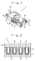
- Figure 1 is a perspective view of an ink jet printer head according to a first embodiment of the present invention.
- Figure 2 is a partial longitudinal sectional view of the ink jet printer head broken away in right-angled direction to longer direction of grooves.
- An ink jet printer head 1 has multi-layered piezoelectric member 4 formed by layered two piezoelectric members 2 and 3 (refer Figure 2) comprising from piezoelectric material like PZT (lead zirconate titanate).
- the polarization direction of the piezoelectric members 2 and 3 are reverse along thickness thereof.
- the multi-layered piezoelectric member 4 provides a plurality of grooves 5 opening toward upper and front surface of the multi-layered piezoelectric member 4 in parallel. Grinding technology using dicing with a diamond wheel, which is used for IC wafer cutting, is uses for forming these grooves 5.
- Each grooves 5 is divided by a plurality of supports 6.
- the grooves 5 is determined in depth range of 0.2 - 1.0 mm (up-and-down direction in Figure 2), width range of 20 - 200 ⁇ m (right and left direction in Figure 2), and length range of 1 - 500 mm(right angled direction to the paper in Figure 2).
- the inner surface of the grooves 5 and the upper surface of the multi-layered piezoelectric member 4 provides a plurality of electrodes 7 forming by the electroless nickel plating method.
- nickel is used for the material forming the electrodes 7, but the present invention does not limit the material of the electrodes 7 to nickel.
- gold, copper or the like may be used as the material of the electrodes 7.
- the nozzle plate 10 has a thickness of 10 - 100 ⁇ m.
- the lid 12 provides an ink supply channel 15 as an ink channel at backside thereof.
- the ink supply channel 15 allows an ink tank (not shown) containing the ink to connect via a pair of ink supply pipes 14 for supplying each pressure chamber 13 (described below).
- the pressure chambers 13 are produced. Each pressure chamber 13 is connected to each other via the ink channel 15.
- the ink jet printer head 1 is connected to a controller (not shown) and a power source (not shown) via a flexible cable (not shown).
- driving pulse (voltage), printing data or the like is input into the ink jet printer head 1 via the flexible cable.
- the electricity flows through the ink filled in each pressure chamber 13 via the ink filled up in the ink channel 15.
- the electricity flowing through the ink may cause the ink to generate electrolysis so as to generate bubbles in the pressure chamber 13.
- the electricity flowing through the ink also may cause the electrodes 7 to precipitate the solid-state material by the electrophoresis. Consequently, the electrodes may not operate correctly.
- the ink jet printer head 1 in order to avoid above mentioned problem, provides the insulation layer 16 comprised from polyurea by vapor deposition polymerization method on the surface of the electrodes 7 contacting to the ink, that is, the inner surface of the pressure chambers 13.
- the vapor deposition polymerization method is defined as the method for forming the organic macromolecule material on the substrate by adding the monomer evaporated by thermal energy and activated thereby to the substrate for forming the layer so as to generate polymerization reaction on the substrate.
- the insulation layer 16 is formed by polyurea in the first embodiment of the present invention, but polyimide, polyimideamide, polyamide, or polyazomethine, for instance, may be used for forming the insulation layer 16.
- the insulation layer 16 is formed by using a vapor deposition polymerization apparatus 17 shown in Figure 3 in this embodiment.
- FIG. 3 is a block schematic diagram of the vapor deposition polymerization apparatus 17.
- the vapor deposition polymerization apparatus 17 has a chamber 19 containing a stage 18 for holding a sample (the piezoelectric member 2 and 3 on which the grooves 5 and the electrodes 7 are formed in this embodiment) that is intended to form a layer by using vapor deposition polymerization.
- the stage 18 provides a temperature control mechanism (not shown). The temperature of the sample can be kept in ordinary temperature (outside temperature) by the temperature control mechanism since the insulation layer 16 is comprised from polyerea.
- the chamber 19 contains inside temperature control mechanism (not shown) for controlling the inside temperature of the chamber 19.
- the inside temperature of the chamber 19 is kept in temperature range of ordinary temperature to 50 ° C since the insulation layer 16 is comprised from polyerea.
- the chamber 19 also provides a pressure reducing mechanism (not shown) for reducing the pressure in the chamber 19.
- the pressure reducing mechanism may be structured as the mechanism that compels the air in the chamber 19 to exhaust to outside of the chamber 19 with a fan or the like.
- a mixing tank 19 is provided on the chamber 19.
- the mixing tank 19 connects with the chamber 19 via a shower plate 21 having a plurality of holes.
- the vapor deposition polymerizing apparatus 17 provides a plurality of evaporation tanks 22 containing source monomer material for adding to the sample.
- Each evaporation tanks 22 contains 4, 4' diaminophenylmethane (MDA) and 4, 4' diphenylmethaneisocyanato as the source monomer material used for forning the insulation layer 16 comprised from polyurea.
- Each evaporation tanks 22 contains heating mechanism (not shown) for heating the source monomer material.
- Each evaporation tanks 22 connects with the mixing tank 20 via a plurality of monomer introduction pipes 23 respectively.
- Each monomer introduction pipes 23 provides a plurality of valves 24 being capable of opening and closing the monomer introduction pipes 23. The monomer introduction pipes 23 are kept in close by the valves 24 except when vapor deposition polymerization is executed.
- step for forming the insulation layer 16 will be explained.
- multi-layered piezoelectric member 4 the grooves 5 of which is formed the electrodes 7 is attached to the stage 18 so as to direct the upper surface on which the grooves 5 are formed toward upper direction. Portions not forming the insulation layer 16 like electrodes 7 to which the flexible cable will connect or the like should be masked previously.
- the evaporation tanks 22 are heated by using a heating mechanism.
- the heated source monomer material evaporates as vapor.
- the monomer introduction pipes 23 are opened after the source monomer was vaporized sufficiently.
- vaporized source monomer material is introduced into the mixing tank 20 via the monomer introduction pipes 23.
- Several kind of monomers are mixed in the mixing tank 20 so as to generate mixed monomer in the mixing tank 20.
- the pressure of the inside of the chamber 19 is reduced by using a pressure reducing mechanism.
- the inside pressure of the mixing tank 20 becomes different to the inside pressure of the chamber 19, so that the mixed monomer is introduced into the chamber via the shower plate 21.
- the mixing monomer introduced into the chamber 19 adds to the multi-layered piezoelectric member 4.
- the source monomer material added on the surface of the multi-layered piezoelectric member 4 begins to deposit to the surface of the multi-layered piezoelectric member 4 on condition that the temperature of the multi-layered piezoelectric member 4 and the inside of the chamber 19 are controlled. Then, the insulation layer 16 comprised from polyerea is formed on the surface of the multi-layered piezoelectric member 4.
- the materials desired to form as the layer is added to the substrate in unit of monomer so as to deposit on the substrate, so that the monomer molecule penetrates to the substrate satisfactorily even though the substrate has complicated form, and the insulation layer 16 can be formed uniformly to even fine portion regardless of shape of the substrate thereby.
- the insulation layer 16 is formed by using the vapor deposition polymerization method having high adhesion and throwing power, under finishing to the surface of the multi-layered piezoelectric member 4 can be eliminated.
- the present invention using the vapor deposition polymerization has advantage to be able to form the insulation layer 16 uniformly to even fine portion, and the operability and workability for forming the insulation layer 16 can be improved thereby.
- the present invention presents the method for covering the electrodes 7 with insulation layer 16 comprised from polyurea, which is one of organic macromolecule material, by using the vapor deposition polymerization method having high adhesion and throwing power, so that the electrodes 7 not arranged on the same plane can be covered satisfactorily at the same time.
- the ink jet printer head 1 of the present invention is capable of using for a long time in steady without deterioration of the ink in case of using conductive ink like water ink.
- the polarization direction of the piezoelectric members 2 and 3 is set at right angle to the direction of the electric field generated by applying voltage to the piezoelectric members 2 and 3.
- the ink jet printer head 1 using shear mode strain of the present invention is capable of using for a long time in steady without deterioration of the piezoelectric member.
- the first embodiment of the present invention introduces the step for forming the insulation layer 16 before attaching the nozzle plate 10 and lid 12 to the multi-layered piezoelectric member 4. But, this step is not limited for manufacturing the ink jet printer head 1 of the present invention. As other embodiment, the insulation layer 16 may be formed after attaching the nozzle plate 10 and lid 12 to the multi-layered piezoelectric member 4, under appreciation of high throwing power of the vapor deposition polymerization. This modified step can eliminate the masking operation to the portions not forming the insulation layer 16 like the portions forming electrode 7 or the like.
- the first embodiment of the present invention also introduces the step for forming the insulation layer 16 out of polyurea in order to prevent the deterioration with respect to the polarization property of the electrodes 2 and 3 caused by over heat.
- polyimide can be used for the material of the insulation layer 16 on condition that a method not causing the deterioration to the polarization property of the electrodes 2 and 3, for instance:
- a second embodiment of the present invention is now explained with reference to Figure 4.
- the same parts as those in the first embodiment are designated by the same reference numerals, and are not again explained herein.
- the polarization direction of the piezoelectric member is different to the same of the firs embodiment of the present invention.
- the piezoelectric member is polarized in right and left direction in Figure 4.
- Figure 4 is a partial longitudinal sectional view of an ink jet printer head broken away in right-angled direction to longer direction of grooves according to a second embodiment of the present invention.
- the ink jet printer head 25 provides a piezoelectric member 27 layered on a substrate 26.
- a plurality of electrodes 28 is provided between the substrate 26 and the piezoelectric member 27.
- the substrate 26 and the piezoelectric member 27 are adhered via the electrodes 28 by conductive adhesive (not shown).
- the ink jet printer 25 provides a plurality of grooves 30 divided in parallel with certain interval by a plurality of supports 29 formed with the substrate 26 and the piezoelectric member 27. The upper and front of the grooves 30 is opened.
- the lid 32 closing upper openings 31 of the grooves 30.
- the lid 32 provides a common electrode 33 at a surface facing to the ink jet printer head 25.
- the lid 32 connects to the upper surface of the supports 29 via the common electrodes 33 by conductive adhesive (not shown).
- the lid 32 also provides an ink channel (not shown) for supplying ink to each pressure chambers 35.
- the front openings of the grooves 30 are closed by a nozzle plate 10 having a plurality of ink nozzles 9.
- the pressure chambers 35 are formed at the grooves 30 in condition of closing the upper openings 31 and the front openings of the grooves 30 with the lid 32 and the nozzle plate 10.
- an insulation layer 36 is formed on the surface of the electrodes 28 which contacts to the ink by using vapor deposition polymerization method before closing the upper openings 31 of the grooves 30 with the lid 32.
- the insulation layer 36 is formed on whole inner surface of the pressure chambers 35 because it can improve operability and workability for forming the insulation layer 36 as compared with a process to mask the portions other than the electrodes 28 in the pressure chamber 35.
- the insulation layer 36 covering the electrodes 28 prevents electricity to flow through the ink, so that the ink jet printer head 25 of the present invention is capable of using for a long time in steady without deterioration of the ink, producing bubbles in the ink or the like.
- the vapor deposition polymerization method may be executed in condition of closing the upper openings 31 with lid 32 so as to cover the electrodes 28 and common electrode 33 surely with the insulation layer 36.
- the insolating layer 36 covering not only the electrodes 28 but also common electrode 33 is able to prevent the electricity to flow through the ink surely.
- the insulation layer 36 may be formed before closing the front opening of the grooves 30 with the nozzle plate 10 or after closing the front opening of the grooves 30 with the nozzle plate 10.
- a third embodiment of the present invention is now explained with reference to Figure 6.
- the same parts as those in the first and second embodiments are designated by the same reference numerals, and are not again explained herein.
- the polarization direction of the piezoelectric member is determined as one direction. This point is different to the first and second embodiments of the present invention.
- Such type of ink jet printer head will be called normal mode type hereinafter.
- Figure 6 is a partial horizontal sectional view of the ink jet printer head broken away along longer direction of grooves according to a third embodiment of the present invention.
- An ink jet printer head 37 arranges a plurality of multi-layered piezoelectric members 38 on a substrate 39 in certain interval. This arrangement produces a plurality of grooves 40 between the multi-layered piezoelectric members 38.
- the multi-layered piezoelectric members 38 operate as a plurality of supports.
- the grooves 40 are formed by the arrangement that the multi-layered piezoelectric members 38 formed as cubic form previously are disposed on the substrate 39. Thus, the grooves 40 are formed easily even though the multi-layered piezoelectric member 38 is used.
- Each multi-layered piezoelectric members 38 provides a pair of electrodes 41 at both side thereof (the right and left surfaces of the multi-layered piezoelectric member 38 in Figure 6). These electrodes 41 are connected with the controller (not shown) and the power source (not shown) for supplying voltage to each multi-layered piezoelectric members 38 via the flexible cable (not shown).
- a front opening 43 of the grooves 40 are closed with the nozzle plate 10 having a plurality of nozzles 9.
- the lid provides an ink channel (refer in Figure 1) for supplying ink to each pressure chamber 44 described below.
- the pressure chambers 44 are formed at the grooves 40 in condition of closing the grooves 40 with the nozzle plate 10, the fillers 42 and the lid.
- the pair of multi-layered piezoelectric members 38 corresponding to the electrodes 41 to which the voltage is applied deforms so as to increase the volume in the pressure chambers 44 and restores consequently so as to decrease the volume in the pressure chambers 44.
- Such restoration of the pair of multi-layered piezoelectric members 38 causes the ink in the pressure chambers 44 to be pressed so as to jet the ink from the nozzles 9 as ink drops.
- insulation layers 45 comprised form polyimide are formed on the surface of the multi-layered piezoelectric members 38 which contact to the ink by using vapor deposition polymerization method before closing the front openings 43 of the grooves 40 with the nozzle plate 10.
- the insulation layers 45 comprised form polyimide resin, are formed on the surface of the electrodes 41, which contacts to the ink, in this embodiment.
- the evaporation tank 22 (refer in Figure 1) contains pyromelliticdianhydride (PDMA) and 4, 4' diaminodiphenylether (ODA) as the source polymer material.
- PDMA pyromelliticdianhydride
- ODA 4' diaminodiphenylether
- the source monomer material is added to the surface of the substrate 39 on which the multi-layered piezoelectric members 38 and the fillers 42 are attached and masked at certain portion, in condition of keeping temperature of 170 - 230 °C in the chamber.
- a macromolecule layer of amino acid is layered on the surface of the grooves 40.
- the macromolecule layer has hydrophilic amino acid in this state.
- the substrate 39 is heated in temperature of over 250 ° C so as to cause the amino acid to imidate.
- the inner surface of the grooves 40 is covered by polyimide resin layer.
- the present invention does not limited for causing the amino acid to imidiate.
- Imidiate can be progressed to the extent of obtaining satisfactory property as the ink jet printer head by increasing process time in temperature 220 ° C as compared with temperature 250 ° C, for instance.
- piezoelectric material the property of which is deteriorated in temperature 250 ° C but is not deteriorated in temperature 220 ° C, for instance, so that wide choice of the piezoelectric material being capable of applying to the ink jet printer head can be obtain.
- the insulation layer 45 covering the electrodes 41 prevents electricity to flow through the ink, so that the ink jet printer head 37 of the present invention is capable of using for a long time in steady without deterioration of the ink, producing bubbles in the ink or the like.
- PZT may cause deterioration of the polarization in high temperature as mentioned above, and the piezoelectric property may be deteriorated thereby.
- the polarization can be executed after forming the insulation layers 45 by using electrodes for driving, for instance, even though the multi-layered piezoelectric member 38 was headed in temperature of over 250 ° C for imidate.
- the polarization can be executed again by using electrodes for driving, for instance, even though the polarization property of the multi-layered piezoelectric member 38 is deteriorated while the ink jet printer head 37 is manufactured.
- PZT not polarized previously can be polarized later by using electrodes for driving, for instance, if the polarization directions are same.
- productivity with respect to the normal mode ink jet printer head 37 being capable of polarizing after manufacturing can be improved. Further, since the cost of polyimide is low, using polyimide as the insulation layers 45 can decrease product cost for forming the insulation layers 45.
- the insulation layers 45 comprised from polyimide is applied for the normal mode ink jet printer head 37, but the present invention does not limit such structure.
- the insulation layer 45 can be formed from polyimide on condition that PZT having heat resistance not causing the deterioration in the forming temperature of the layer is used.
- the multi-layered piezoelectric members 38 of this embodiment has cubic shape, the insulation layers 45 can be easily formed to the individual multi-layered piezoelectric members 38 having the electrodes 41 using well known process thereby.
- the process requires arraying the multi-layered piezoelectric members 38 on which the insulation layers 45 have been formed. Thus, the process is complicated.
- the plurality of insulation layers 45 can be formed at the same time by using vapor deposition polymerization method after arraying the multi-layered piezoelectric members 38 on which the insulation layers 45 have been formed, so that the operation for forming the insulation layers 45 on the inside of the grooves 40 can be executed easily.
- This embodiment introduces to form the insulation layers 45 before attaching the nozzle plate 10 and the lid to the multi-layered piezoelectric members 38. But, the invention does not limit to form the insulation layers 45 by the process. Since the vapor deposition polymerization method contributes high throwing power, the insulation layers 45 may be formed after attaching the nozzle plate 10 and the lid.
- this embodiment introduces to form the insulation layers 45 from polyimide resin, but the present invention does not limit to form the insulation layers 45 from polyimide resin.
- the insulation layers 45 may be formed from polyurea, for instance.
- a fourth embodiment of the present invention is now explained with reference to Figure 7.
- the same parts as those in the first, second and third embodiments are designated by the same reference numerals, and are not again explained herein.
- polarization direction of the multi-layered piezoelectric member is different to the third embodiment of the present invention.
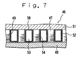
- Figure 7 is a partial longitudinal sectional view of an ink jet printer head broken away in right-angled direction to longer direction of grooves according to a fourth embodiment of the present invention.
- An ink jet printer head 46 arranges a plurality of multi-layered piezoelectric members 47 on a substrate 48 in certain interval. This arrangement produces a plurality of grooves 49 between the multi-layered piezoelectric members 47.
- the multi-layered piezoelectric members 47 operate as a plurality of supports.
- the grooves 49 are formed by the arrangement that the multi-layered piezoelectric members 47 formed as cubic form previously are disposed on the substrate 48. Thus, the grooves 49 are formed easily even though the multi-layered piezoelectric member 47 is used.
- the lid 51 provides an ink channel (not shown but refer in Figure 1).
- the lid 51 of this embodiment has flexibility which deforms according to the deformation of the multi-layered piezoelectric member 47.
- a front opening of the grooves 49, as same to the first and second embodiment of the present invention, are closed with the nozzle plate 10 having a plurality of nozzles 9.
- pressure chambers 53 are formed at inside of the grooves 49 in condition of closing the grooves 49 with the nozzle plate 10, the fillers 42 and the lid.
- each pressure chamber 53 Inside of each pressure chambers 53 provides an electrode 52.
- the electrodes 52 are connected with the controller (not shown) and the power source (not shown) for supplying voltage to each multi-layered piezoelectric members 47 via the flexible cable (not shown).
- the pair of multi-layered piezoelectric members 47 corresponding to the electrodes 52 to which the voltage is applied deforms so as to increase the volume in the pressure chambers 53 and restores consequently so as to decrease the volume in the pressure chambers 53.
- Such restoration of the pair of multi-layered piezoelectric members 47 causes the ink in the pressure chambers 53 to be pressed so as to jet the ink from the nozzles 9 as ink drops.
- insulation layers 54 are formed on the surface of the electrodes 52 which contact to the ink by using vapor deposition polymerization method after closing the upper openings 50 of the grooves 49 with the lid 51.
- the insulation layers 54 comprised form polyimide resin, are formed on the surface of the electrodes 52 which contacts to the ink in this embodiment.
- the insulation layer 54 covering the electrodes 52 prevents electricity to flow through the ink, so that the ink jet printer head 46 of the present invention is capable of using for a long time in steady without deterioration of the ink, producing bubbles in the ink or the like.
- PZT may cause deterioration of the polarization in high temperature as mentioned above, and the piezoelectric property may be deteriorated thereby.
- the polarization can be executed after forming the insulation layers 54 by using electrodes for driving, for instance, even though the multi-layered piezoelectric member 47 was headed in temperature of over 250 ° C for imidate.
- the polarization can be executed again by using electrodes for driving, for instance, even though the polarization property of the multi-layered piezoelectric member 47 is deteriorated while the ink jet printer head 46 is manufactured.
- PZT not polarized previously can be polarized later by using electrodes for driving, for instance, if the polarization directions are same.
- productivity with respect to the normal mode ink jet printer head 46 being capable of polarizing after manufacturing can be improved. Further, since the cost of polyimide is low, using polyimide as the insulation layers 54 can decrease product cost for forming the insulation layers 54.
- the multi-layered piezoelectric members 47 of this embodiment has cubic shape, the insulation layers 54 can be easily formed to the individual multi-layered piezoelectric members 47 having the electrodes 52 using well known process thereby.
- the process requires arraying the multi-layered piezoelectric members 47 on which the insulation layers 54 have been formed. Thus, the process is complicated.
- the plurality of insulation layers 54 can be formed at the same time by using vapor deposition polymerization method after arraying the multi-layered piezoelectric members 47 on which the insulation layers 54 have been formed, so that the operation for forming the insulation layers 54 on the inside of the grooves 49 can be executed easily.
- This embodiment introduces to form the insulation layers 54 before attaching the lid 51 to the multi-layered piezoelectric members 47. But, the invention does not limit to form the insulation layers 54 by the process. Since the vapor deposition polymerization method contributes high throwing power, the insulation layers 54 may be formed after attaching the lid 51.
- this embodiment introduces to form the insulation layers 54 from polyimide resin, but the present invention does not limit to form the insulation layers 54 from polyimide resin.
- the insulation layers 54 may be formed from polyurea, for instance.
- a fifth embodiment of the present invention is now explained with reference to Figure 8. Since ink jet printer head of this embodiment is difference to the first, second, third and fourth embodiment of the present invention, it is described together with process for manufacturing the same.
- the process requests forming a plurality of concave portions 57 on an upper surface of a piezoelectric member 56.
- Concavities 58 and convexity 59 are formed on the upper surface of the piezoelectric member 56 thereby as shown in Figure 8(B).
- an electrode layer 60 is formed on the concavities 58 and the convexity 59 of the piezoelectric member 56 by using spattering or the like as shown in Figure 8(C). Then, the process requests cutting the electrode layer 60 and the upper portion of the piezoelectric member 56 between the concavities 58 and convexity 59 (step) so as to divide the concavities 58 and convexity 59 by narrow grooves 61. Thus, continued electrode layer 60 is divided so as to form a plurality of electrodes 62. A plurality of convex portions 63 is also formed in each concave portion 57.
- a plurality of electrodes 64 are formed on the bottom surface of the piezoelectric member 56 so as to corresponding to the electrodes 62 formed on the upper surface of the piezoelectric member 56. Explanation for forming the electrodes 62 is eliminated because it is well known, but the bottom surface of the piezoelectric member 56 is plane, the electrodes 64 having pattern corresponding to the electrodes 62 formed on the upper surface of the piezoelectric member 56 can be easily formed thereby.
- a lid 65 is attached to the upper surface of the piezoelectric member 56.
- a nozzle plate having nozzles (not shown) is also attached to the front surface of the piezoelectric member 56.
- a plurality of pressure chambers 66 is provided as shown in Figure 8(E).
- the piezoelectric member 56 is grinded from upper together with the lid 65, so that a plurality of dividing grooves 67 are formed which divides each convexity 59.
- a plurality of supports 68 is provided as shown in Figure 8(F).
- a insulation layer 69 covering the electrodes 62 provided on the supports 68 and the electrode 62 provided on the convex portion 63 with polyimide resin is formed on inside of each pressure chamber 66 (refer in Figure 8(G)).
- the insulation layer 69 is formed after attaching the lid 65 to the piezoelectric member 56 and before attaching the nozzle plate to the piezoelectric member 56.
- the insulation layer 69 covering the inside of the pressure chamber 66 prevents electricity to flow through the ink, so that the ink jet printer head 46 of the present invention is capable of using for a long time in steady without deterioration of the ink, producing bubbles in the ink or the like.
- the ink jet printer head 55 of this embodiment has complicated shape in inside of the pressure chamber 66, forming layer method by using vapor deposition polymerization method is especially effective. That is, the insulation layer 69 can be formed uniformly to the fine portion in the pressure chamber 66 by using vapor deposition polymerization method.
- insulation layer 69 may be formed before attaching the lid 65 to the piezoelectric member 56 or after attaching the lid 65 to the piezoelectric member 56.
- this embodiment introduces to form the insulation layers 54 from polyimide resin, but the present invention does not limit to form the insulation layers 54 from polyimide resin.
- the insulation layers 54 may be formed from polyurea, for instance.
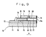
- Figure 9 is a longitudinal sectional view of an ink jet printer head broken away along longer direction of grooves according to a sixth embodiment of the present invention.
- a substrate 73 formed a plurality of grooves 72 in parallel is attached to a base plate 71.
- the grooves 72 are formed so as to open both ends. One end of the grooves 72 is closed with a nozzle plate 74 having a plurality of nozzles 74a. At the other end of the grooves 72 a piezoelectric member 75 is inserted. Upper surface and bottom surface of the piezoelectric member 75 provides electrodes 76 respectively. The piezoelectric member 75 deforms longer direction of the grooves 72 (shown in arrow A in Figure 9) with applying voltage to the electrodes 76. The piezoelectric member 75 is adhered at rear portion of the grooves 72 by adhesive B.
- An upper opening 77 of the grooves 72 is closed with a lid 79 providing a supply nozzle 78.
- the supply nozzle 78 is connected with an ink tank (not shown) and an ink channel (not shown) for supplying ink to each pressure chambers 80 described below.
- the grooves 72, the nozzle plate 74, and the lid 79 form the pressure chambers 80.
- the piezoelectric member 75 In operation of the ink jet printer head 70, voltage is applied to the electrodes 76 provided on the piezoelectric member 75 which intends to jet the ink.
- the piezoelectric member 75 corresponding to the electrodes 76 to which the voltage is applied is expanded and contracted in its length direction. Since the piezoelectric members 75 are adhered to the substrate 73 by the adhesion B, The piezoelectric member 75 corresponding to the electrodes 76 to which the voltage is applied deforms toward right direction in Figure 9 so as to decrease the volume in the pressure chamber 80, the ink contained in the pressure chamber 80 jets as ink drop thereby.
- insulation layers 81 comprised form polyimide are formed on the surface of the piezoelectric members 75 having the electrodes 76. The insulation layers 81 are formed before closing one opening ends of the grooves 72.
- the insulation layer 81 covering the electrodes 76 prevents electricity to flow through the ink, so that the ink jet printer head 70 of the present invention is capable of using for a long time in steady without deterioration of the ink, producing bubbles in the ink or the like.
- the piezoelectric members 75 of this embodiment have cubic shape, and the insulation layers 81 can be easily formed to the piezoelectric members 75 using well known process thereby. Especially, the insulation layers 81 can be formed at the same time by using vapor deposition polymerization method after fabricating the ink jet printer head 70, so that the operability and workability for forming the insulation layers 81 can be improved.
Landscapes
- Engineering & Computer Science (AREA)
- Manufacturing & Machinery (AREA)
- Particle Formation And Scattering Control In Inkjet Printers (AREA)
Abstract
Description
- The present application is based on Japanese Priority Document 2000-191906 filed on June 6, 2000, the content of which is incorporated herein by reference.
- The present invention relates to an ink jet printer head being capable of using conductive ink like water ink and the manufacturing the same.
- An ink jet printer, comprising a pressure chamber, at least part of which is formed out of piezoelectric member, a nozzle formed in the pressure chamber, and means for applying voltage to the piezoelectric member, so as to jet ink form the pressure chamber through the nozzle using shear mode strain of the pressure chamber generated by applying voltage to the piezoelectric member, has been used so far.
- Japanese laid-open publication (unexamined publication) document Hei 8-52872 discloses an ink jet printer head having a pressure chamber covered with an insulation layer consisting of parylene (registered trade mark) or the like by using CVD (Chemical vapor Deposition), for preventing deterioration of the ink. The document Hei 8-52872 discloses the technique to protect an electrode provided in the pressure chamber by the insulation layer so as to prevent flowing up electricity in the ink in case of using conductive ink so that the ink may be protected from deterioration caused by flowing up electricity therein. The document Hei 8-52872 also discloses the technique to be capable of uniformly forming the insulation layer consisting of parylene or the like on a substrate having complicated and fine shape like inner surface of the pressure chamber of the ink jet printer head or the like by CDV method.
- Japanese laid-open publication (unexamined publication) document Hei 8-290569 discloses an ink jet printer head, which applies voltage to an electrode on a piezoelectric member, portion inserted into a pressure chamber of which is coated by polyimide resin by using spin coating method for obtaining stability and durability of the piezoelectric member, to generate displacement of the piezoelectric member toward a nozzle so as to jet the ink contained in the pressure chamber. Thus, the document Hei 8-290569 discloses the technique for preventing the ink to penetrate into the piezoelectric member so as to improve stability and durability of the piezoelectric member.
- The drawbacks of the above techniques disclosed in the documents Hei 8-52872 and 8-290569 are now explained.
- Because the parylene vapor deposition layer formed by CVD method has small adhesion to the substrate, it is required to execute under finishing like silane coupling finishing when the insulation layer is formed. Thus, the technique disclosed in the document Hei 8-52872 has drawback that the step of forming insulation layer is increased, so that the operability or workability for forming insulation layer is complicated and troublesome.
- The technique disclosed in the document Hei 8-290569 improves stability and durability of the piezoelectric member. However, the technique has drawback that the electricity flows up into the ink contained in the pressure chamber via an ink channel in case of using conductive ink because the electrode is attached to the polyimide resin coated on the piezoelectric member.
- Accordingly, an object of the present invention is to obtain an ink jet printer head and method for manufacturing the same being capable of using the ink jet printer head for a long time in steady without deterioration of the piezoelectric member and the ink in case of using conductive ink like water ink.
- Another object of the present invention is to obtain an ink jet printer head and method for manufacturing the same being capable of using the ink jet printer head for a long time in steady without deterioration of the piezoelectric member and the ink in case of using conductive ink like water ink, even though the piezoelectric member deteriorates polarization property under high temperature.
- These and further object of the present invention are achieved by the novel ink jet printer head and method for manufacturing the same of the present invention.
- According to the novel ink jet printer head of the present invention, comprising a pressure chamber, at least part of which is formed out of piezoelectric member, to be supplied ink, a nozzle connecting the pressure chamber to outside, an electrode for applying voltage to the piezoelectric member; and an insulation layer, covering the electrode, comprising from organic macromolecule material to be capable of forming by vapor deposition polymerization method. Accordingly, the electrode provided on the piezoelectric member is covered with insulation layer comprising from organic macromolecule material, which is capable of forming by vapor deposition polymerization method, having high adhesion and throwing power, so that the electrodes not disposed on the same plane respectively may be covered with insulation layer.
- According to the novel method for an ink jet printer head of the present invention, comprising the steps of forming a pressure chamber, at least part of which is formed out of piezoelectric member, forming an electrode for applying voltage to the piezoelectric member; and covering the electrode with an insulation layer comprising from organic macromolecule material by vapor deposition polymerization method. Accordingly, the electrode provided on the piezoelectric member is covered with insulation layer comprising from organic macromolecule material, which is capable of forming by vapor deposition polymerization method, having high adhesion and throwing power, so that the electrodes not disposed on the same plane respectively may be covered with insulation layer.
- A more complete appreciation of the present invention and many of the attendant advantages thereof will be readily obtained as the same becomes better understood by reference to the following detailed description when considered in connection with the accompanying drawings, wherein:
- Figure 1 is a perspective view of an ink jet printer head according to a first embodiment of the present invention;
- Figure 2 is a partial longitudinal sectional view of the ink jet printer head broken away in right-angled direction to longer direction of grooves;
- Figure 3 is a block schematic diagram of a vapor deposition polymerization apparatus;
- Figure 4 is a partial longitudinal sectional view of an ink jet printer head broken away in right-angled direction to longer direction of grooves according to a second embodiment of the present invention;
- Figure 5 is a partial longitudinal sectional view of the ink jet printer head broken away in right-angled direction to longer direction of grooves according to the second embodiment with modification of the present invention;
- Figure 6 is a partial horizontal sectional view of the ink jet printer head broken away along longer direction of grooves according to a third embodiment of the present invention;
- Figure 7 is a partial longitudinal sectional view of an ink jet printer head broken away in right-angled direction to longer direction of grooves according to a fourth embodiment of the present invention; and
- Figure 8 is a partial longitudinal sectional view of an ink jet printer head broken away in right-angled direction to longer direction of grooves with steps for manufacturing the same according to a fifth embodiment of the present invention; and
- Figure 9 is a longitudinal sectional view of an ink jet printer head broken away along longer direction of grooves according to a sixth embodiment of the present invention.
-
- A first embodiment of the present invention is now explained with reference to Figures 1 - 3. The first embodiment directs to an ink jet printer.
- Figure 1 is a perspective view of an ink jet printer head according to a first embodiment of the present invention. Figure 2 is a partial longitudinal sectional view of the ink jet printer head broken away in right-angled direction to longer direction of grooves.
- An ink jet printer head 1 has multi-layered piezoelectric member 4 formed by layered two piezoelectric members 2 and 3 (refer Figure 2) comprising from piezoelectric material like PZT (lead zirconate titanate). The polarization direction of the
piezoelectric members 2 and 3 are reverse along thickness thereof. - The multi-layered piezoelectric member 4 provides a plurality of
grooves 5 opening toward upper and front surface of the multi-layered piezoelectric member 4 in parallel. Grinding technology using dicing with a diamond wheel, which is used for IC wafer cutting, is uses for forming thesegrooves 5. Eachgrooves 5 is divided by a plurality ofsupports 6. Thegrooves 5 is determined in depth range of 0.2 - 1.0 mm (up-and-down direction in Figure 2), width range of 20 - 200 µm (right and left direction in Figure 2), and length range of 1 - 500 mm(right angled direction to the paper in Figure 2). - The inner surface of the
grooves 5 and the upper surface of the multi-layered piezoelectric member 4 provides a plurality of electrodes 7 forming by the electroless nickel plating method. - It is eliminated to explain with respect to the electroless nickel plating method since the technique is well known, but, the method presents to form the electrodes 7 even in the fine area like the inner surface of the
grooves 5. - In the first embodiment of the present invention, nickel is used for the material forming the electrodes 7, but the present invention does not limit the material of the electrodes 7 to nickel. For instance, gold, copper or the like may be used as the material of the electrodes 7.
- A plurality of front openings 8 of the
grooves 5, which connects thegrooves 5 to the front surface of the multi-layered piezoelectric member 4, is plugged up with anozzle plate 10 having a plurality ofnozzles 9. Thenozzle plate 10 has a thickness of 10 - 100 µm. - A plurality of
upper openings 11 of thegrooves 5, which connects thegrooves 5 to the upper surface of the multi-layered piezoelectric member 4, is plugged up with alid 12. Thelid 12 provides anink supply channel 15 as an ink channel at backside thereof. Theink supply channel 15 allows an ink tank (not shown) containing the ink to connect via a pair ofink supply pipes 14 for supplying each pressure chamber 13 (described below). - In condition of closing the front opening 8 and the
upper opening 11 of the multi-layered piezoelectric member 4 (head substrate) with thenozzle plate 10 and thelid 12, thepressure chambers 13 are produced. Eachpressure chamber 13 is connected to each other via theink channel 15. The ink jet printer head 1 is connected to a controller (not shown) and a power source (not shown) via a flexible cable (not shown). Thus, in printing operation, driving pulse (voltage), printing data or the like is input into the ink jet printer head 1 via the flexible cable. - In operation of the ink jet printer using the ink jet printer head 1, voltage is applied to the pair of electrodes 7 disposed at both inner sides of the
pressure chamber 13 contributing ink jetted in condition of supplying ink into thepressure chamber 13. The pair ofsupports 6 corresponding to the electrodes 7 to which the voltage is applied deforms so as to increase the volume in thepressure chamber 13 by shear mode strain of thepiezoelectric members 2 and 3 having reverse polarization directions each other. Then, the pair ofsupports 6 restores rapidly by applying voltage in reverse polarity to the electrodes 7. Such rapid restoration of the pair ofsupports 6 causes the ink in thepressure chamber 13 to be pressed so as to jet the ink from thenozzle 9 as ink drop. - When the voltage is applied to the electrodes 7 in condition of filling the
pressure chamber 13 of the ink jet printer head 1 with high conductive ink like water ink in, the electricity flows through the ink filled in eachpressure chamber 13 via the ink filled up in theink channel 15. Thus, the electricity flowing through the ink may cause the ink to generate electrolysis so as to generate bubbles in thepressure chamber 13. The electricity flowing through the ink also may cause the electrodes 7 to precipitate the solid-state material by the electrophoresis. Consequently, the electrodes may not operate correctly. - The ink jet printer head 1, in order to avoid above mentioned problem, provides the
insulation layer 16 comprised from polyurea by vapor deposition polymerization method on the surface of the electrodes 7 contacting to the ink, that is, the inner surface of thepressure chambers 13. The vapor deposition polymerization method is defined as the method for forming the organic macromolecule material on the substrate by adding the monomer evaporated by thermal energy and activated thereby to the substrate for forming the layer so as to generate polymerization reaction on the substrate. Theinsulation layer 16 is formed by polyurea in the first embodiment of the present invention, but polyimide, polyimideamide, polyamide, or polyazomethine, for instance, may be used for forming theinsulation layer 16. - Next, step of forming the
insulation layer 16 which covers the electrodes 7 will be explained hereinafter. Theinsulation layer 16 is formed by using a vapordeposition polymerization apparatus 17 shown in Figure 3 in this embodiment. - Figure 3 is a block schematic diagram of the vapor
deposition polymerization apparatus 17. The vapordeposition polymerization apparatus 17 has achamber 19 containing astage 18 for holding a sample (thepiezoelectric member 2 and 3 on which thegrooves 5 and the electrodes 7 are formed in this embodiment) that is intended to form a layer by using vapor deposition polymerization. Thestage 18 provides a temperature control mechanism (not shown). The temperature of the sample can be kept in ordinary temperature (outside temperature) by the temperature control mechanism since theinsulation layer 16 is comprised from polyerea. - The
chamber 19 contains inside temperature control mechanism (not shown) for controlling the inside temperature of thechamber 19. The inside temperature of thechamber 19 is kept in temperature range of ordinary temperature to 50 ° C since theinsulation layer 16 is comprised from polyerea. - The
chamber 19 also provides a pressure reducing mechanism (not shown) for reducing the pressure in thechamber 19. The pressure reducing mechanism may be structured as the mechanism that compels the air in thechamber 19 to exhaust to outside of thechamber 19 with a fan or the like. - A mixing
tank 19 is provided on thechamber 19. The mixingtank 19 connects with thechamber 19 via ashower plate 21 having a plurality of holes. - The vapor
deposition polymerizing apparatus 17 provides a plurality ofevaporation tanks 22 containing source monomer material for adding to the sample. Eachevaporation tanks 22 contains 4, 4' diaminophenylmethane (MDA) and 4, 4' diphenylmethaneisocyanato as the source monomer material used for forning theinsulation layer 16 comprised from polyurea. - Each
evaporation tanks 22 contains heating mechanism (not shown) for heating the source monomer material. Eachevaporation tanks 22 connects with the mixingtank 20 via a plurality ofmonomer introduction pipes 23 respectively. Eachmonomer introduction pipes 23 provides a plurality ofvalves 24 being capable of opening and closing themonomer introduction pipes 23. Themonomer introduction pipes 23 are kept in close by thevalves 24 except when vapor deposition polymerization is executed. - Next, step for forming the
insulation layer 16 will be explained. First of all, multi-layered piezoelectric member 4, thegrooves 5 of which is formed the electrodes 7 is attached to thestage 18 so as to direct the upper surface on which thegrooves 5 are formed toward upper direction. Portions not forming theinsulation layer 16 like electrodes 7 to which the flexible cable will connect or the like should be masked previously. - As next stage, the
evaporation tanks 22 are heated by using a heating mechanism. The heated source monomer material evaporates as vapor. Themonomer introduction pipes 23 are opened after the source monomer was vaporized sufficiently. Thus, vaporized source monomer material is introduced into the mixingtank 20 via themonomer introduction pipes 23. Several kind of monomers are mixed in themixing tank 20 so as to generate mixed monomer in themixing tank 20. - The pressure of the inside of the
chamber 19 is reduced by using a pressure reducing mechanism. Thus, the inside pressure of the mixingtank 20 becomes different to the inside pressure of thechamber 19, so that the mixed monomer is introduced into the chamber via theshower plate 21. - The mixing monomer introduced into the
chamber 19 adds to the multi-layered piezoelectric member 4. The source monomer material added on the surface of the multi-layered piezoelectric member 4 begins to deposit to the surface of the multi-layered piezoelectric member 4 on condition that the temperature of the multi-layered piezoelectric member 4 and the inside of thechamber 19 are controlled. Then, theinsulation layer 16 comprised from polyerea is formed on the surface of the multi-layered piezoelectric member 4. - In operation of the vapor deposition polymerization method, the materials desired to form as the layer is added to the substrate in unit of monomer so as to deposit on the substrate, so that the monomer molecule penetrates to the substrate satisfactorily even though the substrate has complicated form, and the
insulation layer 16 can be formed uniformly to even fine portion regardless of shape of the substrate thereby. - Also, since the
insulation layer 16 is formed by using the vapor deposition polymerization method having high adhesion and throwing power, under finishing to the surface of the multi-layered piezoelectric member 4 can be eliminated. - Further more, forming layer method, other than the vapor deposition polymerization, requiring under finishing to the substrate has difficulties to process the under finishing to the substrate having complicated form like the ink jet printer head 1. Thus, the present invention using the vapor deposition polymerization has advantage to be able to form the
insulation layer 16 uniformly to even fine portion, and the operability and workability for forming theinsulation layer 16 can be improved thereby. - The present invention presents the method for covering the electrodes 7 with
insulation layer 16 comprised from polyurea, which is one of organic macromolecule material, by using the vapor deposition polymerization method having high adhesion and throwing power, so that the electrodes 7 not arranged on the same plane can be covered satisfactorily at the same time. Thus, the ink jet printer head 1 of the present invention is capable of using for a long time in steady without deterioration of the ink in case of using conductive ink like water ink. - In the ink jet printer head 1 of the present embodiment, the polarization direction of the
piezoelectric members 2 and 3 is set at right angle to the direction of the electric field generated by applying voltage to thepiezoelectric members 2 and 3. In the ink jet printer head 1 using shear mode strain of thepiezoelectric members 2 and 3, it is difficult to polarize thepiezoelectric members 2 and 3 again after deterioration of the polarization with respect to thepiezoelectric members 2 and 3. - The polarization property deteriorates by the over heat of the piezoelectric members 2 and 4, for instance. On the contrast, present embodiment introduces polyurea for the material of the
insulation layer 16 being capable of beginning deposition in low temperature, so that theinsulation layer 16 can be formed on the electrodes 7 in sufficient low temperature to the extent of not deteriorating the polarization property of thepiezoelectric members 2 and 3. Accordingly, the ink jet printer head 1 using shear mode strain of the present invention is capable of using for a long time in steady without deterioration of the piezoelectric member. - The first embodiment of the present invention introduces the step for forming the
insulation layer 16 before attaching thenozzle plate 10 andlid 12 to the multi-layered piezoelectric member 4. But, this step is not limited for manufacturing the ink jet printer head 1 of the present invention. As other embodiment, theinsulation layer 16 may be formed after attaching thenozzle plate 10 andlid 12 to the multi-layered piezoelectric member 4, under appreciation of high throwing power of the vapor deposition polymerization. This modified step can eliminate the masking operation to the portions not forming theinsulation layer 16 like the portions forming electrode 7 or the like. - The first embodiment of the present invention also introduces the step for forming the
insulation layer 16 out of polyurea in order to prevent the deterioration with respect to the polarization property of theelectrodes 2 and 3 caused by over heat. However, polyimide can be used for the material of theinsulation layer 16 on condition that a method not causing the deterioration to the polarization property of theelectrodes 2 and 3, for instance: - a method for forming the
pressure chamber 13 by using piezoelectric material not causing the deterioration of the polarization under temperature of deposition reaction in imidate; - a method for forming the
insulation layer 16 using imidate by not temperature condition but chemical; or the like is used. Further more, theinsulation layer 16 can be formed from polyimide on condition that PZT having heat resistance not causing the deterioration in the forming temperature of the layer is used. -
- A second embodiment of the present invention is now explained with reference to Figure 4. The same parts as those in the first embodiment are designated by the same reference numerals, and are not again explained herein. In the second embodiment of the present invention, the polarization direction of the piezoelectric member is different to the same of the firs embodiment of the present invention. The piezoelectric member is polarized in right and left direction in Figure 4.
- Figure 4 is a partial longitudinal sectional view of an ink jet printer head broken away in right-angled direction to longer direction of grooves according to a second embodiment of the present invention. The ink
jet printer head 25 provides apiezoelectric member 27 layered on asubstrate 26. A plurality ofelectrodes 28 is provided between thesubstrate 26 and thepiezoelectric member 27. Thesubstrate 26 and thepiezoelectric member 27 are adhered via theelectrodes 28 by conductive adhesive (not shown). - The
ink jet printer 25 provides a plurality ofgrooves 30 divided in parallel with certain interval by a plurality ofsupports 29 formed with thesubstrate 26 and thepiezoelectric member 27. The upper and front of thegrooves 30 is opened. - There is provided a
lid 32 closingupper openings 31 of thegrooves 30. Thelid 32 provides acommon electrode 33 at a surface facing to the inkjet printer head 25. Thelid 32 connects to the upper surface of thesupports 29 via thecommon electrodes 33 by conductive adhesive (not shown). Thelid 32 also provides an ink channel (not shown) for supplying ink to eachpressure chambers 35. - As same to the first embodiment of the present invention, the front openings of the
grooves 30 are closed by anozzle plate 10 having a plurality ofink nozzles 9. - Then, the
pressure chambers 35 are formed at thegrooves 30 in condition of closing theupper openings 31 and the front openings of thegrooves 30 with thelid 32 and thenozzle plate 10. - In operation of an ink jet printer using the ink
jet printer head 25, voltage is applied to the pair ofelectrodes 28 disposed at both inner sides of thepressure chambers 35 contributing ink jetted in condition of supplying ink into thepressure chambers 35. The pair ofpiezoelectric members 27 corresponding to theelectrodes 28 to which the voltage is applied deforms so as to increase the volume in thepressure chambers 35 and restores consequently so as to decrease the volume in thepressure chambers 44. Such restoration of the pair ofpiezoelectric members 27 causes the ink in thepressure chambers 35 to be pressed so as to jet the ink from thenozzles 9 as ink drops. - When the voltage is applied to the
electrodes 28 in condition of filling thepressure chambers 35 of the inkjet printer head 25 with conductive ink, the electricity flows through the ink filled in eachpressure chambers 35 via the ink filled up in the ink channel. The electricity flowing through the ink may cause deterioration of the ink, deterioration of the polarization property with respect to thepiezoelectric member 27, or the like. Thus, in the second embodiment of the present invention, aninsulation layer 36 is formed on the surface of theelectrodes 28 which contacts to the ink by using vapor deposition polymerization method before closing theupper openings 31 of thegrooves 30 with thelid 32. - The
insulation layer 36 is formed on whole inner surface of thepressure chambers 35 because it can improve operability and workability for forming theinsulation layer 36 as compared with a process to mask the portions other than theelectrodes 28 in thepressure chamber 35. - Accordingly, in case of using conductive ink, the
insulation layer 36 covering the electrodes 28 (the inner surface of the pressure chambers 35) prevents electricity to flow through the ink, so that the inkjet printer head 25 of the present invention is capable of using for a long time in steady without deterioration of the ink, producing bubbles in the ink or the like. - It is not necessary to cover the
common electrode 33 because common voltage is applied to thecommon electrode 33 in eachpressure chambers 35. However, as modified embodiment of the second embodiment of the present invention, as shown in Figure 5, the vapor deposition polymerization method may be executed in condition of closing theupper openings 31 withlid 32 so as to cover theelectrodes 28 andcommon electrode 33 surely with theinsulation layer 36. Theinsolating layer 36 covering not only theelectrodes 28 but alsocommon electrode 33 is able to prevent the electricity to flow through the ink surely. - Further more, the
insulation layer 36 may be formed before closing the front opening of thegrooves 30 with thenozzle plate 10 or after closing the front opening of thegrooves 30 with thenozzle plate 10. - A third embodiment of the present invention is now explained with reference to Figure 6. The same parts as those in the first and second embodiments are designated by the same reference numerals, and are not again explained herein. In the third embodiment of the present invention, the polarization direction of the piezoelectric member is determined as one direction. This point is different to the first and second embodiments of the present invention. Such type of ink jet printer head will be called normal mode type hereinafter.
- Figure 6 is a partial horizontal sectional view of the ink jet printer head broken away along longer direction of grooves according to a third embodiment of the present invention. An ink
jet printer head 37 arranges a plurality of multi-layeredpiezoelectric members 38 on asubstrate 39 in certain interval. This arrangement produces a plurality ofgrooves 40 between the multi-layeredpiezoelectric members 38. Thus, the multi-layeredpiezoelectric members 38 operate as a plurality of supports. - Generally, it is difficult to form the
grooves 40 to the multi-layeredpiezoelectric member 38. In the inkjet printer head 37 of the present embodiment, thegrooves 40 are formed by the arrangement that the multi-layeredpiezoelectric members 38 formed as cubic form previously are disposed on thesubstrate 39. Thus, thegrooves 40 are formed easily even though the multi-layeredpiezoelectric member 38 is used. - Each multi-layered
piezoelectric members 38 provides a pair ofelectrodes 41 at both side thereof (the right and left surfaces of the multi-layeredpiezoelectric member 38 in Figure 6). Theseelectrodes 41 are connected with the controller (not shown) and the power source (not shown) for supplying voltage to each multi-layeredpiezoelectric members 38 via the flexible cable (not shown). - There are provided a plurality of
fillers 42 to close the end of thegrooves 40 respectively at the end of the grooves. - A
front opening 43 of thegrooves 40, as same to the first and second embodiment of the present invention, are closed with thenozzle plate 10 having a plurality ofnozzles 9. - Upper openings of the
grooves 40 are closed with lid (not shown). The lid provides an ink channel (refer in Figure 1) for supplying ink to eachpressure chamber 44 described below. - Then, the
pressure chambers 44 are formed at thegrooves 40 in condition of closing thegrooves 40 with thenozzle plate 10, thefillers 42 and the lid. - In operation of the ink
jet printer head 37, voltage is applied to the pair ofelectrodes 41 disposed at both inner sides of thepressure chambers 44 contributing ink jetted in condition of supplying ink into thepressure chambers 44. The pair of multi-layeredpiezoelectric members 38 corresponding to theelectrodes 41 to which the voltage is applied deforms so as to increase the volume in thepressure chambers 44 and restores consequently so as to decrease the volume in thepressure chambers 44. Such restoration of the pair of multi-layeredpiezoelectric members 38 causes the ink in thepressure chambers 44 to be pressed so as to jet the ink from thenozzles 9 as ink drops. - When the voltage is applied to the
electrodes 41 in condition of filling thepressure chambers 44 of the inkjet printer head 37 with conductive ink, the electricity flows through the ink filled in eachpressure chambers 44 via the ink filled up in the ink channel. The electricity flowing through the ink may cause deterioration of the ink or the like. Thus, in the third embodiment of the present invention, insulation layers 45 comprised form polyimide are formed on the surface of the multi-layeredpiezoelectric members 38 which contact to the ink by using vapor deposition polymerization method before closing thefront openings 43 of thegrooves 40 with thenozzle plate 10. - The insulation layers 45, comprised form polyimide resin, are formed on the surface of the
electrodes 41, which contacts to the ink, in this embodiment. In process of forming the insulation layers 45, the evaporation tank 22 (refer in Figure 1) contains pyromelliticdianhydride (PDMA) and 4, 4' diaminodiphenylether (ODA) as the source polymer material. - Detailed description is eliminated, but as a process for forming the insulation layers 45, the source monomer material is added to the surface of the
substrate 39 on which the multi-layeredpiezoelectric members 38 and thefillers 42 are attached and masked at certain portion, in condition of keeping temperature of 170 - 230 °C in the chamber. Thus, a macromolecule layer of amino acid is layered on the surface of thegrooves 40. The macromolecule layer has hydrophilic amino acid in this state. Thus, thesubstrate 39 is heated in temperature of over 250 ° C so as to cause the amino acid to imidate. Then, the inner surface of thegrooves 40 is covered by polyimide resin layer. - In this embodiment, it is introduced to cause the amino acid on the
substrate 39 to imidate in temperature 250 ° C, but the present invention does not limited for causing the amino acid to imidiate. Imidiate can be progressed to the extent of obtaining satisfactory property as the ink jet printer head by increasing process time in temperature 220 ° C as compared with temperature 250 ° C, for instance. Thus, it is possible to use piezoelectric material, the property of which is deteriorated in temperature 250 ° C but is not deteriorated in temperature 220 ° C, for instance, so that wide choice of the piezoelectric material being capable of applying to the ink jet printer head can be obtain. - Accordingly, in case of using conductive ink, the
insulation layer 45 covering theelectrodes 41 prevents electricity to flow through the ink, so that the inkjet printer head 37 of the present invention is capable of using for a long time in steady without deterioration of the ink, producing bubbles in the ink or the like. - Generally, PZT may cause deterioration of the polarization in high temperature as mentioned above, and the piezoelectric property may be deteriorated thereby. However, in this embodiment, since the normal mode ink
jet printer head 37 having same polarization directions with respect to the piezoelectric members is used the polarization can be executed after forming the insulation layers 45 by using electrodes for driving, for instance, even though the multi-layeredpiezoelectric member 38 was headed in temperature of over 250 ° C for imidate. - In this embodiment, since the normal mode ink
jet printer head 37 having same polarization direction with respect to the piezoelectric members is used the polarization can be executed again by using electrodes for driving, for instance, even though the polarization property of the multi-layeredpiezoelectric member 38 is deteriorated while the inkjet printer head 37 is manufactured. - Further more, PZT not polarized previously can be polarized later by using electrodes for driving, for instance, if the polarization directions are same.
- Thus, productivity with respect to the normal mode ink
jet printer head 37 being capable of polarizing after manufacturing can be improved. Further, since the cost of polyimide is low, using polyimide as the insulation layers 45 can decrease product cost for forming the insulation layers 45. - In this embodiment, the insulation layers 45 comprised from polyimide is applied for the normal mode ink
jet printer head 37, but the present invention does not limit such structure. Theinsulation layer 45 can be formed from polyimide on condition that PZT having heat resistance not causing the deterioration in the forming temperature of the layer is used. - The multi-layered
piezoelectric members 38 of this embodiment has cubic shape, the insulation layers 45 can be easily formed to the individual multi-layeredpiezoelectric members 38 having theelectrodes 41 using well known process thereby. However, the process requires arraying the multi-layeredpiezoelectric members 38 on which the insulation layers 45 have been formed. Thus, the process is complicated. - In this embodiment, the plurality of insulation layers 45 can be formed at the same time by using vapor deposition polymerization method after arraying the multi-layered
piezoelectric members 38 on which the insulation layers 45 have been formed, so that the operation for forming the insulation layers 45 on the inside of thegrooves 40 can be executed easily. - This embodiment introduces to form the insulation layers 45 before attaching the
nozzle plate 10 and the lid to the multi-layeredpiezoelectric members 38. But, the invention does not limit to form the insulation layers 45 by the process. Since the vapor deposition polymerization method contributes high throwing power, the insulation layers 45 may be formed after attaching thenozzle plate 10 and the lid. - Further, this embodiment introduces to form the insulation layers 45 from polyimide resin, but the present invention does not limit to form the insulation layers 45 from polyimide resin. The insulation layers 45 may be formed from polyurea, for instance.
- A fourth embodiment of the present invention is now explained with reference to Figure 7. The same parts as those in the first, second and third embodiments are designated by the same reference numerals, and are not again explained herein. In this embodiment, polarization direction of the multi-layered piezoelectric member is different to the third embodiment of the present invention.
- Figure 7 is a partial longitudinal sectional view of an ink jet printer head broken away in right-angled direction to longer direction of grooves according to a fourth embodiment of the present invention. An ink
jet printer head 46 arranges a plurality of multi-layeredpiezoelectric members 47 on asubstrate 48 in certain interval. This arrangement produces a plurality ofgrooves 49 between the multi-layeredpiezoelectric members 47. Thus, the multi-layeredpiezoelectric members 47 operate as a plurality of supports. - Generally, it is difficult to form the
grooves 49 to the multi-layeredpiezoelectric member 47. In the inkjet printer head 46 of the present embodiment, thegrooves 49 are formed by the arrangement that the multi-layeredpiezoelectric members 47 formed as cubic form previously are disposed on thesubstrate 48. Thus, thegrooves 49 are formed easily even though the multi-layeredpiezoelectric member 47 is used. -
upper openings 50 of thegrooves 49 are closed withlid 51. Thelid 51 provides an ink channel (not shown but refer in Figure 1). Thelid 51 of this embodiment has flexibility which deforms according to the deformation of the multi-layeredpiezoelectric member 47. - A front opening of the
grooves 49, as same to the first and second embodiment of the present invention, are closed with thenozzle plate 10 having a plurality ofnozzles 9. - There are provided a plurality of fillers to close the end of the
grooves 49 respectively at the end of the grooves. - Then,
pressure chambers 53 are formed at inside of thegrooves 49 in condition of closing thegrooves 49 with thenozzle plate 10, thefillers 42 and the lid. - Inside of each
pressure chambers 53 provides anelectrode 52. Theelectrodes 52 are connected with the controller (not shown) and the power source (not shown) for supplying voltage to each multi-layeredpiezoelectric members 47 via the flexible cable (not shown). - In operation of the ink
jet printer head 46, voltage is applied to the pair ofelectrodes 52 disposed at both inner sides of thepressure chambers 53 contributing ink jetted in condition of supplying ink into thepressure chambers 53. The pair of multi-layeredpiezoelectric members 47 corresponding to theelectrodes 52 to which the voltage is applied deforms so as to increase the volume in thepressure chambers 53 and restores consequently so as to decrease the volume in thepressure chambers 53. Such restoration of the pair of multi-layeredpiezoelectric members 47 causes the ink in thepressure chambers 53 to be pressed so as to jet the ink from thenozzles 9 as ink drops. - When the voltage is applied to the
electrodes 52 in condition of filling thepressure chambers 53 of the inkjet printer head 46 with conductive ink, the electricity flows through the ink filled in eachpressure chambers 53 via the ink filled up in the ink channel. The electricity flowing through the ink may cause deterioration of the ink or the like. Thus, in the fourth embodiment of the present invention, insulation layers 54 are formed on the surface of theelectrodes 52 which contact to the ink by using vapor deposition polymerization method after closing theupper openings 50 of thegrooves 49 with thelid 51. - The insulation layers 54, comprised form polyimide resin, are formed on the surface of the
electrodes 52 which contacts to the ink in this embodiment. - Accordingly, in case of using conductive ink, the
insulation layer 54 covering theelectrodes 52 prevents electricity to flow through the ink, so that the inkjet printer head 46 of the present invention is capable of using for a long time in steady without deterioration of the ink, producing bubbles in the ink or the like. - Generally, PZT may cause deterioration of the polarization in high temperature as mentioned above, and the piezoelectric property may be deteriorated thereby. However, in this embodiment, since the normal mode ink
jet printer head 46 having same polarization directions with respect to the piezoelectric members is used the polarization can be executed after forming the insulation layers 54 by using electrodes for driving, for instance, even though the multi-layeredpiezoelectric member 47 was headed in temperature of over 250 ° C for imidate. - In this embodiment, since the normal mode ink
jet printer head 46 having same polarization direction with respect to the piezoelectric members is used the polarization can be executed again by using electrodes for driving, for instance, even though the polarization property of the multi-layeredpiezoelectric member 47 is deteriorated while the inkjet printer head 46 is manufactured. - Further more, PZT not polarized previously can be polarized later by using electrodes for driving, for instance, if the polarization directions are same.
- Thus, productivity with respect to the normal mode ink
jet printer head 46 being capable of polarizing after manufacturing can be improved. Further, since the cost of polyimide is low, using polyimide as the insulation layers 54 can decrease product cost for forming the insulation layers 54. - The multi-layered
piezoelectric members 47 of this embodiment has cubic shape, the insulation layers 54 can be easily formed to the individual multi-layeredpiezoelectric members 47 having theelectrodes 52 using well known process thereby. However, the process requires arraying the multi-layeredpiezoelectric members 47 on which the insulation layers 54 have been formed. Thus, the process is complicated. - In this embodiment, the plurality of insulation layers 54 can be formed at the same time by using vapor deposition polymerization method after arraying the multi-layered
piezoelectric members 47 on which the insulation layers 54 have been formed, so that the operation for forming the insulation layers 54 on the inside of thegrooves 49 can be executed easily. - This embodiment introduces to form the insulation layers 54 before attaching the
lid 51 to the multi-layeredpiezoelectric members 47. But, the invention does not limit to form the insulation layers 54 by the process. Since the vapor deposition polymerization method contributes high throwing power, the insulation layers 54 may be formed after attaching thelid 51. - Further, this embodiment introduces to form the insulation layers 54 from polyimide resin, but the present invention does not limit to form the insulation layers 54 from polyimide resin. The insulation layers 54 may be formed from polyurea, for instance.
- A fifth embodiment of the present invention is now explained with reference to Figure 8. Since ink jet printer head of this embodiment is difference to the first, second, third and fourth embodiment of the present invention, it is described together with process for manufacturing the same.
- First of all, as shown in Figure 8(A), the process requests forming a plurality of
concave portions 57 on an upper surface of apiezoelectric member 56. Concavities 58 andconvexity 59 are formed on the upper surface of thepiezoelectric member 56 thereby as shown in Figure 8(B). - As next step, an
electrode layer 60 is formed on theconcavities 58 and theconvexity 59 of thepiezoelectric member 56 by using spattering or the like as shown in Figure 8(C). Then, the process requests cutting theelectrode layer 60 and the upper portion of thepiezoelectric member 56 between theconcavities 58 and convexity 59 (step) so as to divide theconcavities 58 andconvexity 59 bynarrow grooves 61. Thus, continuedelectrode layer 60 is divided so as to form a plurality ofelectrodes 62. A plurality ofconvex portions 63 is also formed in eachconcave portion 57. - As next process, a plurality of
electrodes 64 are formed on the bottom surface of thepiezoelectric member 56 so as to corresponding to theelectrodes 62 formed on the upper surface of thepiezoelectric member 56. Explanation for forming theelectrodes 62 is eliminated because it is well known, but the bottom surface of thepiezoelectric member 56 is plane, theelectrodes 64 having pattern corresponding to theelectrodes 62 formed on the upper surface of thepiezoelectric member 56 can be easily formed thereby. - As next process, a
lid 65 is attached to the upper surface of thepiezoelectric member 56. A nozzle plate having nozzles (not shown) is also attached to the front surface of thepiezoelectric member 56. Thus, a plurality ofpressure chambers 66 is provided as shown in Figure 8(E). - As last process, the
piezoelectric member 56 is grinded from upper together with thelid 65, so that a plurality of dividinggrooves 67 are formed which divides eachconvexity 59. Thus, a plurality ofsupports 68 is provided as shown in Figure 8(F). - In operation of the ink
jet printer head 55, reverse voltages are applied to theelectrodes 62 provided at thesupports 68 of thepressure chamber 66 which intends to jet the ink and theelectrode 62 provided on theconvex portion 63 of itspressure chamber 66 in condition of supplying ink into thepressure chambers 66. The supports 68 and theconvex portion 63 corresponding to theelectrodes 52 to which the voltage is applied deform so as to increase the volume in thepressure chambers 66 and restores consequently so as to decrease the volume in thepressure chambers 66. Such restoration of thesupports 68 and theconvex portion 63 causes the ink in thepressure chambers 66 to be pressed so as to jet the ink from thenozzle 9 as ink drop. - In the ink
jet printer head 55 of the present invention, high electric field is generated on the bottom side of the piezoelectric member 56 (making shear mode complex) in case of setting electric potentials with respect to theelectrodes 62 provided on thesupports 68 and theelectrode 62 provided on theconvex portion 63 equal, so that thepiezoelectric member 56 does not work desirably. Thus, ainsulation layer 69 covering theelectrodes 62 provided on thesupports 68 and theelectrode 62 provided on theconvex portion 63 with polyimide resin is formed on inside of each pressure chamber 66 (refer in Figure 8(G)). Theinsulation layer 69 is formed after attaching thelid 65 to thepiezoelectric member 56 and before attaching the nozzle plate to thepiezoelectric member 56. - Accordingly, in case of using conductive ink, the
insulation layer 69 covering the inside of thepressure chamber 66 prevents electricity to flow through the ink, so that the inkjet printer head 46 of the present invention is capable of using for a long time in steady without deterioration of the ink, producing bubbles in the ink or the like. - Since the ink
jet printer head 55 of this embodiment has complicated shape in inside of thepressure chamber 66, forming layer method by using vapor deposition polymerization method is especially effective. That is, theinsulation layer 69 can be formed uniformly to the fine portion in thepressure chamber 66 by using vapor deposition polymerization method. - Further, the
insulation layer 69 may be formed before attaching thelid 65 to thepiezoelectric member 56 or after attaching thelid 65 to thepiezoelectric member 56. - Further more, this embodiment introduces to form the insulation layers 54 from polyimide resin, but the present invention does not limit to form the insulation layers 54 from polyimide resin. The insulation layers 54 may be formed from polyurea, for instance.
- A sixth embodiment of the present invention is now explained with reference to Figure 9. The same parts as those in the first embodiment are designated by the same reference numerals, and are not again explained herein.
- Figure 9 is a longitudinal sectional view of an ink jet printer head broken away along longer direction of grooves according to a sixth embodiment of the present invention. A
substrate 73 formed a plurality ofgrooves 72 in parallel is attached to abase plate 71. - The
grooves 72 are formed so as to open both ends. One end of thegrooves 72 is closed with anozzle plate 74 having a plurality ofnozzles 74a. At the other end of the grooves 72 apiezoelectric member 75 is inserted. Upper surface and bottom surface of thepiezoelectric member 75 provideselectrodes 76 respectively. Thepiezoelectric member 75 deforms longer direction of the grooves 72 (shown in arrow A in Figure 9) with applying voltage to theelectrodes 76. Thepiezoelectric member 75 is adhered at rear portion of thegrooves 72 by adhesive B. - An
upper opening 77 of thegrooves 72 is closed with alid 79 providing asupply nozzle 78. Thesupply nozzle 78 is connected with an ink tank (not shown) and an ink channel (not shown) for supplying ink to eachpressure chambers 80 described below. - Thus, the
grooves 72, thenozzle plate 74, and thelid 79 form thepressure chambers 80. - In operation of the ink
jet printer head 70, voltage is applied to theelectrodes 76 provided on thepiezoelectric member 75 which intends to jet the ink. Thepiezoelectric member 75 corresponding to theelectrodes 76 to which the voltage is applied is expanded and contracted in its length direction. Since thepiezoelectric members 75 are adhered to thesubstrate 73 by the adhesion B, Thepiezoelectric member 75 corresponding to theelectrodes 76 to which the voltage is applied deforms toward right direction in Figure 9 so as to decrease the volume in thepressure chamber 80, the ink contained in thepressure chamber 80 jets as ink drop thereby. - When the voltage is applied to the
electrodes 76 in condition of filling thepressure chambers 80 of the inkjet printer head 70 with conductive ink, since eachpressure chambers 80 provides plus andminus electrodes 76, the electricity flows through the ink filled in eachpressure chambers 80. The electricity flowing through the ink may cause deterioration of the ink, generating bubbles from the ink, or the like. Thus, in this embodiment of the present invention, insulation layers 81 comprised form polyimide are formed on the surface of thepiezoelectric members 75 having theelectrodes 76. The insulation layers 81 are formed before closing one opening ends of thegrooves 72. - Accordingly, in case of using conductive ink, the
insulation layer 81 covering theelectrodes 76 prevents electricity to flow through the ink, so that the inkjet printer head 70 of the present invention is capable of using for a long time in steady without deterioration of the ink, producing bubbles in the ink or the like. - The
piezoelectric members 75 of this embodiment have cubic shape, and the insulation layers 81 can be easily formed to thepiezoelectric members 75 using well known process thereby. Especially, the insulation layers 81 can be formed at the same time by using vapor deposition polymerization method after fabricating the inkjet printer head 70, so that the operability and workability for forming the insulation layers 81 can be improved. - Obviously, numerous modifications and variations of the present invention are possible in light of the above teachings. It is therefore to be understood that within the scope of the appended claims, the invention may be practiced otherwise than as specifically described herein.
Claims (12)
- An ink jet printer head, comprising:a pressure chamber, at least part of which is formed out of piezoelectric member, to be supplied ink;a nozzle connecting the pressure chamber to outside;an electrode for applying voltage to the piezoelectric member; andan insulation layer, covering the electrode, comprising from organic macromolecule material which is capable of forming by vapor deposition polymerization method.
- An ink jet printer head according to claim 1, wherein a plurality of pressure chambers is provided, and ink is supplied into each pressure chamber through an ink channel contributing to connect each pressure chamber to an ink tank.
- An ink jet printer head according to claim 2, wherein the pressure chambers are provided in a space between a pair of supports, at least part of which is formed out of the piezoelectric member, the nozzle and the electrodes are provided in each pressure chamber.
- An ink jet printer head according to claim 2, wherein the pressure chambers are provided in a space between a pair of supports, at least part of which is formed out of the piezoelectric member, the nozzle is provided in each pressure chamber, the electrode comprises a pair of electrodes, at least one of which is provided on each support.
- An ink jet printer head according to claim 1, wherein the electrode comprises a pair of electrodes.
- An ink jet printer head according to claim 1, wherein the insulation layer contains polyurea.
- An ink jet printer head according to claim 1, wherein the insulation layer contains polyimide.
- A method for manufacturing an ink jet printer head, comprising the steps of:forming a pressure chamber, at least part of which is formed out of piezoelectric member;forming an electrode for applying voltage to the piezoelectric member; andcovering the electrode with an insulation layer comprising from organic macromolecule material by vapor deposition polymerization method.
- A method for manufacturing an ink jet printer head according to claim 8, wherein the pressure chamber forming step includes forming a plurality of pressure chambers,further comprising the step of forming an ink channel, contributing to connect each pressure chamber to an ink tank, for supplying into each pressure chamber.
- A method for manufacturing an ink jet printer head according to claim 8, wherein the electrode forming step includes forming a pair of electrodes.
- A method for manufacturing an ink jet printer head according to claim 8, wherein the electrode covering step includes covering the electrode with polyurea.
- A method for manufacturing an ink jet printer head according to claim 8, wherein the electrode covering step includes covering the electrode with polyimide.
Applications Claiming Priority (2)
| Application Number | Priority Date | Filing Date | Title |
|---|---|---|---|
| JP2000191906 | 2000-06-26 | ||
| JP2000191906A JP2002001955A (en) | 2000-06-26 | 2000-06-26 | Ink jet printer head and its manufacturing method |
Publications (2)
| Publication Number | Publication Date |
|---|---|
| EP1167040A1 true EP1167040A1 (en) | 2002-01-02 |
| EP1167040B1 EP1167040B1 (en) | 2008-02-20 |
Family
ID=18691120
Family Applications (1)
| Application Number | Title | Priority Date | Filing Date |
|---|---|---|---|
| EP01305445A Expired - Lifetime EP1167040B1 (en) | 2000-06-26 | 2001-06-22 | Ink jet printer head and method for manufacturing the same |
Country Status (4)
| Country | Link |
|---|---|
| US (1) | US6547374B2 (en) |
| EP (1) | EP1167040B1 (en) |
| JP (1) | JP2002001955A (en) |
| DE (1) | DE60132849T2 (en) |
Cited By (2)
| Publication number | Priority date | Publication date | Assignee | Title |
|---|---|---|---|---|
| US7896630B2 (en) | 2006-12-11 | 2011-03-01 | Regi U.S., Inc. | Rotary device with reciprocating vanes and seals therefor |
| EP3199349A1 (en) * | 2016-01-29 | 2017-08-02 | Toshiba TEC Kabushiki Kaisha | Ink jet head and ink jet printer |
Families Citing this family (3)
| Publication number | Priority date | Publication date | Assignee | Title |
|---|---|---|---|---|
| GB0919404D0 (en) | 2009-11-05 | 2009-12-23 | Xennia Technology Ltd | Inkjet printer |
| JP5606266B2 (en) | 2010-10-26 | 2014-10-15 | 東芝テック株式会社 | Inkjet head |
| CN103963468B (en) * | 2014-05-21 | 2016-02-10 | 北京派和科技股份有限公司 | Piezoelectric ink jet head and comprise the printing device of this piezoelectric ink jet head |
Citations (4)
| Publication number | Priority date | Publication date | Assignee | Title |
|---|---|---|---|---|
| JPH0726023A (en) * | 1993-07-14 | 1995-01-27 | Furukawa Electric Co Ltd:The | Method for producing organic polymer thin film |
| JPH0852872A (en) * | 1994-08-15 | 1996-02-27 | Citizen Watch Co Ltd | Inkjet head and manufacturing method thereof |
| EP0863008A2 (en) * | 1997-01-10 | 1998-09-09 | Konica Corporation | Production method of ink-jet head |
| US6074048A (en) * | 1993-05-12 | 2000-06-13 | Minolta Co., Ltd. | Ink jet recording head including interengaging piezoelectric and non-piezoelectric members and method of manufacturing same |
Family Cites Families (3)
| Publication number | Priority date | Publication date | Assignee | Title |
|---|---|---|---|---|
| JPH0383017A (en) * | 1989-08-28 | 1991-04-09 | Sharp Corp | Production of liquid crystal display device |
| JPH08290569A (en) | 1995-04-24 | 1996-11-05 | Minolta Co Ltd | Ink jet recording device |
| JP3414227B2 (en) * | 1997-01-24 | 2003-06-09 | セイコーエプソン株式会社 | Ink jet recording head |
-
2000
- 2000-06-26 JP JP2000191906A patent/JP2002001955A/en active Pending
-
2001
- 2001-06-22 DE DE60132849T patent/DE60132849T2/en not_active Expired - Lifetime
- 2001-06-22 EP EP01305445A patent/EP1167040B1/en not_active Expired - Lifetime
- 2001-06-25 US US09/887,432 patent/US6547374B2/en not_active Expired - Lifetime
Patent Citations (4)
| Publication number | Priority date | Publication date | Assignee | Title |
|---|---|---|---|---|
| US6074048A (en) * | 1993-05-12 | 2000-06-13 | Minolta Co., Ltd. | Ink jet recording head including interengaging piezoelectric and non-piezoelectric members and method of manufacturing same |
| JPH0726023A (en) * | 1993-07-14 | 1995-01-27 | Furukawa Electric Co Ltd:The | Method for producing organic polymer thin film |
| JPH0852872A (en) * | 1994-08-15 | 1996-02-27 | Citizen Watch Co Ltd | Inkjet head and manufacturing method thereof |
| EP0863008A2 (en) * | 1997-01-10 | 1998-09-09 | Konica Corporation | Production method of ink-jet head |
Non-Patent Citations (3)
| Title |
|---|
| DATABASE WPI Derwent World Patents Index; AN 1995-101963, XP002177727 * |
| PATENT ABSTRACTS OF JAPAN vol. 1995, no. 04 31 May 1995 (1995-05-31) * |
| PATENT ABSTRACTS OF JAPAN vol. 1996, no. 06 28 June 1996 (1996-06-28) * |
Cited By (4)
| Publication number | Priority date | Publication date | Assignee | Title |
|---|---|---|---|---|
| US7896630B2 (en) | 2006-12-11 | 2011-03-01 | Regi U.S., Inc. | Rotary device with reciprocating vanes and seals therefor |
| EP3199349A1 (en) * | 2016-01-29 | 2017-08-02 | Toshiba TEC Kabushiki Kaisha | Ink jet head and ink jet printer |
| CN107020814A (en) * | 2016-01-29 | 2017-08-08 | 东芝泰格有限公司 | Ink gun and ink-jet printer |
| CN107020814B (en) * | 2016-01-29 | 2018-06-12 | 东芝泰格有限公司 | Ink gun and ink-jet printer |
Also Published As
| Publication number | Publication date |
|---|---|
| US6547374B2 (en) | 2003-04-15 |
| DE60132849D1 (en) | 2008-04-03 |
| EP1167040B1 (en) | 2008-02-20 |
| DE60132849T2 (en) | 2009-02-12 |
| US20010055050A1 (en) | 2001-12-27 |
| JP2002001955A (en) | 2002-01-08 |
Similar Documents
| Publication | Publication Date | Title |
|---|---|---|
| CN111788073B (en) | Liquid droplet ejector | |
| US5984447A (en) | L-shaped inkjet print head in which driving voltage is directly applied to driving electrodes | |
| JP4829165B2 (en) | Piezoelectric element manufacturing method and liquid discharge head manufacturing method | |
| US20080034563A1 (en) | Manufacturing method of actuator device and liquid jet apparatus provided wirth actuator device formed by manufacturing method of the same | |
| JP2012096554A (en) | Inkjet printing module | |
| NZ243925A (en) | Manufacture of piezoelectric ink jet printer head | |
| US20130250005A1 (en) | Ink-jet head and method of manufacturing ink-jet head | |
| US7926920B2 (en) | Liquid discharging head and method for producing the liquid discharging head | |
| US9498950B2 (en) | Retaining structure of wiring member, liquid discharge head, liquid discharge device, and liquid discharge apparatus | |
| US7976133B2 (en) | Liquid-jetting apparatus and method for producing the same | |
| US6547374B2 (en) | Ink jet printer head and method for manufacturing the same | |
| JP5288530B2 (en) | Piezoelectric element manufacturing method and liquid discharge head manufacturing method | |
| CN1299319A (en) | Droplet deposition apparatus and method of mfg. same | |
| JP4021687B2 (en) | Inkjet printer head manufacturing method | |
| US6351879B1 (en) | Method of making a printing apparatus | |
| JP6686635B2 (en) | INKJET HEAD, METHOD FOR MANUFACTURING THE SAME, AND INKJET PRINTER | |
| JP4287278B2 (en) | Low voltage inkjet print module | |
| US20090020504A1 (en) | Method for manufacturing ink-jet head | |
| WO1994001284A1 (en) | Ink jet head | |
| US4449134A (en) | Composite ink jet drivers | |
| JP2003266691A (en) | Ink jet printer head and method of manufacturing the same | |
| US5980027A (en) | Ink jet print head including adhesive layers enabling optimal electrode coverage and ink droplet velocity | |
| CN113442586A (en) | Liquid ejection head, liquid ejection device, and actuator | |
| JPH09174861A (en) | Method for manufacturing inkjet printer head | |
| JP3414905B2 (en) | Recording head |
Legal Events
| Date | Code | Title | Description |
|---|---|---|---|
| PUAI | Public reference made under article 153(3) epc to a published international application that has entered the european phase |
Free format text: ORIGINAL CODE: 0009012 |
|
| 17P | Request for examination filed |
Effective date: 20010705 |
|
| AK | Designated contracting states |
Kind code of ref document: A1 Designated state(s): BE CH DE FR GB LI Kind code of ref document: A1 Designated state(s): AT BE CH CY DE DK ES FI FR GB GR IE IT LI LU MC NL PT SE TR |
|
| AX | Request for extension of the european patent |
Free format text: AL;LT;LV;MK;RO;SI |
|
| AKX | Designation fees paid |
Free format text: BE CH DE FR GB LI |
|
| 17Q | First examination report despatched |
Effective date: 20030910 |
|
| GRAP | Despatch of communication of intention to grant a patent |
Free format text: ORIGINAL CODE: EPIDOSNIGR1 |
|
| GRAS | Grant fee paid |
Free format text: ORIGINAL CODE: EPIDOSNIGR3 |
|
| GRAA | (expected) grant |
Free format text: ORIGINAL CODE: 0009210 |
|
| AK | Designated contracting states |
Kind code of ref document: B1 Designated state(s): BE CH DE FR GB LI |
|
| REG | Reference to a national code |
Ref country code: GB Ref legal event code: FG4D |
|
| REG | Reference to a national code |
Ref country code: CH Ref legal event code: EP |
|
| REF | Corresponds to: |
Ref document number: 60132849 Country of ref document: DE Date of ref document: 20080403 Kind code of ref document: P |
|
| PG25 | Lapsed in a contracting state [announced via postgrant information from national office to epo] |
Ref country code: BE Free format text: LAPSE BECAUSE OF FAILURE TO SUBMIT A TRANSLATION OF THE DESCRIPTION OR TO PAY THE FEE WITHIN THE PRESCRIBED TIME-LIMIT Effective date: 20080220 |
|
| PGFP | Annual fee paid to national office [announced via postgrant information from national office to epo] |
Ref country code: CH Payment date: 20080710 Year of fee payment: 8 |
|
| ET | Fr: translation filed | ||
| PLBE | No opposition filed within time limit |
Free format text: ORIGINAL CODE: 0009261 |
|
| STAA | Information on the status of an ep patent application or granted ep patent |
Free format text: STATUS: NO OPPOSITION FILED WITHIN TIME LIMIT |
|
| 26N | No opposition filed |
Effective date: 20081121 |
|
| REG | Reference to a national code |
Ref country code: CH Ref legal event code: PL |
|
| PG25 | Lapsed in a contracting state [announced via postgrant information from national office to epo] |
Ref country code: LI Free format text: LAPSE BECAUSE OF NON-PAYMENT OF DUE FEES Effective date: 20090630 Ref country code: CH Free format text: LAPSE BECAUSE OF NON-PAYMENT OF DUE FEES Effective date: 20090630 |
|
| PGFP | Annual fee paid to national office [announced via postgrant information from national office to epo] |
Ref country code: FR Payment date: 20100709 Year of fee payment: 10 |
|
| REG | Reference to a national code |
Ref country code: FR Ref legal event code: ST Effective date: 20120229 |
|
| PG25 | Lapsed in a contracting state [announced via postgrant information from national office to epo] |
Ref country code: FR Free format text: LAPSE BECAUSE OF NON-PAYMENT OF DUE FEES Effective date: 20110630 |
|
| PGFP | Annual fee paid to national office [announced via postgrant information from national office to epo] |
Ref country code: GB Payment date: 20130619 Year of fee payment: 13 Ref country code: DE Payment date: 20130619 Year of fee payment: 13 |
|
| REG | Reference to a national code |
Ref country code: DE Ref legal event code: R119 Ref document number: 60132849 Country of ref document: DE |
|
| GBPC | Gb: european patent ceased through non-payment of renewal fee |
Effective date: 20140622 |
|
| REG | Reference to a national code |
Ref country code: DE Ref legal event code: R119 Ref document number: 60132849 Country of ref document: DE Effective date: 20150101 |
|
| PG25 | Lapsed in a contracting state [announced via postgrant information from national office to epo] |
Ref country code: DE Free format text: LAPSE BECAUSE OF NON-PAYMENT OF DUE FEES Effective date: 20150101 |
|
| PG25 | Lapsed in a contracting state [announced via postgrant information from national office to epo] |
Ref country code: GB Free format text: LAPSE BECAUSE OF NON-PAYMENT OF DUE FEES Effective date: 20140622 |