Background of the Invention
The present invention relates to a cleaning
apparatus for cleaning an outer surface of a rotary
member by pressing a cleaning web against it and, more
particularly, to a catching detecting method and unit in
the cleaning apparatus which detect that a cleaning web
is caught in a rotary member.
In general, a printing press has a cleaning
apparatus for cleaning the outer surface of a cylinder
serving as a rotary member by urging a belt-like
cleaning cloth against it. EP 0552856 (reference 1)
discloses a cleaning apparatus of this type, the main
part of which is shown in Fig. 11. Referring to Fig. 11,
reference numeral 1 denotes the blanket cylinder of the
printing press. A supply shaft 2 supplies a belt-like
cleaning cloth 6. A take-up shaft 3 takes up the
cleaning cloth 6. Guide rollers 4 and 5 guide the
cleaning cloth 6 to the outer surface of the blanket
cylinder 1. A lever 8 is axially supported by a support
pin 7 and detects that the cleaning cloth 6 is caught.
A tension spring 11 has two ends respectively fixed by
spring catches 9 and 10. A limit switch 12 is actuated
by the lever 8.
The take-up shaft 3 intermittently takes up
the cleaning cloth 6 supplied from the supply shaft 2
through the guide rollers 4 and 5. In this cleaning
apparatus, the cleaning cloth 6 intermittently traveling
between the supply shaft 2 and take-up shaft 3 is
pressed against the rotating blanket cylinder 1 in a
taught state, so the outer surface of the blanket
cylinder 1 is cleaned with it. At this time, since the
blanket cylinder 1 is rotating, the cleaning cloth 6
might be caught in the blanket cylinder 1 during
cleaning. In other words, the cleaning cloth 6 may
adhesively attach to the blanket surface of the blanket
cylinder 1 due to the viscosity of the ink, or may be
torn up for some reason, so the cleaning cloth 6 is
accidentally caught in the rotating blanket cylinder 1.
In this case, in a conventional cleaning
apparatus, the accident causing the cleaning cloth 6 to become
caught is detected in the following manner. When the
cleaning cloth 6 is not caught, a distal end 8b of the
lever 8 is pressed by the traveling cleaning cloth 6
because of the biasing force of the tension spring 11,
and the limit switch 12 is set in the non-operative
state. When the cleaning cloth 6 is caught, the
cleaning cloth 6 is loosened, so the lever 8 is rotated
clockwise in Fig. 11 by the biasing force of the tension
spring 11. A distal end 8b of the lever 8 then presses
an actuator 12a of the limit switch 12 to turn on an
internal contact.
In the above cleaning apparatus, the limit
switch 12 detects that the lever 8 swings in accordance
with a change in tension of the cleaning cloth 6. Hence,
when the cleaning cloth 6 is caught, if the tension of
the cleaning cloth 6 does not change, accidental
catching of the cleaning cloth 6 cannot be detected.
Summary of the Invention
It is an object of the present invention to
provide a cleaning apparatus which can reliably detect
catching of a cleaning cloth even if the tension of the
cleaning cloth does not change, and a method of
detecting catching of the cleaning web in this apparatus.
In order to achieve the above object,
according to the present invention, there is provided a
cleaning apparatus comprising a cleaning web pressed
against a rotary member and adapted to clean an outer
surface of the rotary member, a supply shaft around
which the cleaning web before cleaning is wound and
which rotates in accordance with supply operation of the
cleaning web to the outer surface of the rotary member,
a take-up shaft rotatably driven to take up the cleaning
web supplied from the supply shaft to the outer surface
of the rotary member, signal output means for outputting
a signal corresponding to the rotational speed of the
supply shaft, and detection means for detecting that the
cleaning web is caught in the rotary member on the basis
of a state of the signal output from the signal output
means.
Brief Description of the Drawings
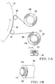
Fig. 1A is a side view showing the main part
of a cleaning apparatus according to an embodiment of
the present invention;
Fig. 1B is an enlarged perspective view of the
detector shown in Fig. 1A;
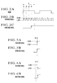
Figs. 2A to 2C are timing charts showing the
principle of catching detection during cleaning by the
catching detection apparatus shown in Fig. 1A;
Figs. 3A and 3B are timing charts showing the
principle of catching detection I during non-cleaning by
the catching detection apparatus shown in Fig. 1A;
Figs. 4A and 4B are timing charts showing the
principle of catching detection I during non-cleaning by
the catching detection apparatus shown in Fig. 1A;
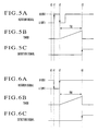
Figs. 5A to 5C are timing charts showing the
principle of catching detection II during non-cleaning
by the catching detection apparatus shown in Fig. 1A;
Figs. 6A to 6C are timing charts showing the
principle of catching detection II during non-cleaning
by the catching detection apparatus shown in Fig. 1A;
Fig. 7 is a block diagram of the catching
detection apparatus shown in Fig. 1A;
Fig. 8 is a plan view of the display screen of
the input/display unit shown in Fig. 1A;
Fig. 9 is a flow chart showing a catching
detection process during cleaning and a catching
detection process I during non-cleaning, which are
performed by the CPU shown in Fig. 7;
Fig. 10 is a flow chart showing a catching
detection process II during non-cleaning by the CPU
shown in Fig. 7; and
Fig. 11 is a side view showing a conventional
cleaning cloth catching detection apparatus.
Description of the Preferred Embodiment
The present invention will be described in
detail with reference to the accompanying drawings.
Fig. 1A shows the main part of a cleaning
apparatus according to an embodiment of the present
invention. Referring to Fig. 1A, reference numeral 101
denotes a blanket cylinder of a printing press. A
supply shaft 102 supplies a belt-like cleaning cloth 106
as a cleaning web. A take-up shaft 103 takes up the
cleaning cloth 106. Guide rollers 104 and 105 guide the
cleaning cloth 106 to the outer surface of the blanket
cylinder 101. The take-up shaft 103 is intermittently
pivoted by a ratchet mechanism so as to take up the
cleaning cloth 106 supplied from the supply shaft 102
through the guide rollers 104 and 105. At this time,
the cleaning cloth 106 intermittently traveling between
the supply shaft 102 and take-up shaft 103 is pressed
against the rotating blanket cylinder 101 in a taut
state, so the outer surface of the blanket cylinder 101
is cleaned with it. The supply shaft 102 is pivoted by
the tension of the cleaning cloth 106 supplied to the
outer surface of the blanket cylinder 101 as the take-up
shaft 103 pivots.
The supply shaft 102 has a cylindrical
detector 113 projecting from its one shaft end, as shown
in Fig. 1B. The detector 113 is rotated together with
the supply shaft 102. The detector 113 has eight
magnetic metal projections 113a arranged equidistantly
on its circumference and extending in the axial
direction. A proximity switch 114 for magnetically
detecting the projections 113a of the detector 113 as
they pass is disposed to oppose the outer surface of the
detector 113. During rotation of the supply shaft 102,
the proximity switch 114 is CN while a projection 113a
passes to output an "H"-level signal, and is OFF while
the next projection 113a passes to output an "L"-level
signal. In other words, the proximity switch 114
outputs a pulsed rotation signal, the output state of
which alternately changes between "H" level and "L"
level, to a catching detection unit 100 in accordance
with rotation of the supply shaft 102.
[Catching Detection During Cleaning]
In the cleaning apparatus with the above
arrangement, abnormal travel of the cleaning cloth 106
during cleaning operation, which is caused by accidental
catching or the like, is detected on the basis of the
output state of the rotation signal supplied from the
proximity switch 114. More specifically, when the
cleaning cloth 106 is caught in the blanket cylinder 101,
the supply shaft 102 rotates at a speed faster than that
during normal cleaning as it is pulled by the caught
cleaning cloth 106. As the rotational speed of the
supply shaft 102 increases, the number of output pulses
from the proximity switch 114 within a predetermined
period of time also increases.
The catching detection unit 100 counts the
pulses of the rotation signal supplied from the
proximity switch 114. When the pulse count exceeds a
preset value within a predetermined period of time, i.e.,
when the rotational speed of the supply shaft 2 exceeds
a predetermined value, the catching detection unit 100
determines that the cleaning cloth 106 is caught in the
blanket cylinder 101.
In the above example, whether the cleaning
cloth 106 is caught is checked by counting the output
pulses within the predetermined period of time.
Alternatively, the catching detection unit 100 may
determine that the cleaning cloth 106 is caught in the
blanket cylinder 101 when the frequency of the rotation
signal exceeds a predetermined frequency at least once
or continuously for a predetermined period of time.
When the cleaning cloth 106 is caught in the blanket
cylinder 101, the rotational speed of the supply shaft
102 increases, and the frequency of the rotation signal
also increases. Hence, disturbed travelling of the
cleaning cloth 1C6 caused when the cleaning cloth 106 is
caught in the blanket cylinder 101 can be detected in
the same manner by checking whether or not the frequency
of the rotation signal exceeds the predetermined value.
Figs. 2A to 2C show timing charts for
detecting catching during cleaning operation. As shown
in Figs. 2A and 23, the number of times the rotation
signal from the proximity switch 114 rises to "H" level,
i.e., the number of times the proximity switch 114 is
turned on, within a predetermined period of time T
counted by the timer is counted. When this count
becomes 4 or more during the predetermined period of
time T, an "H"-level detection signal indicating that
the cleaning cloth 106 is caught in the blanket cylinder
101 is output, as shown in Fig. 2C.
[Catching Detection I During Non-Cleaning (Wait Mode
After Cleaning Is Ended)]
Catching of the cleaning cloth 106 during
non-cleaning operation is also detected on the basis of
the output state of the rotation signal supplied from
the proximity switch 114. More specifically, when the
cleaning operation is ended, take-up operation for the
cleaning cloth 106 by the take-up shaft 103 is stopped,
and the cleaning cloth 106 is separated from the outer
surface of the blanket cylinder 101. At this time,
during a state wherein the printing press keeps
operation, i.e., in the wait mode in a state wherein the
blanket cylinder 101 is kept rotating, the cleaning
cloth 106 is accidentally caught in the blanket cylinder
101 by some cause.
As a countermeasure, the output state
("H" or "L" level) of the rotation signal from the
proximity switch 114 is stored with the supply shaft 102
being stopped at the end of cleaning. The stored output
state of the rotation signal and the output state of the
rotation signal in the wait mode are compared. If the
output states differ, it is determined that the cleaning
cloth 106 is caught in the blanket cylinder 101.
Figs. 3A and 3B, and Figs. 4A and 4B show
timing charts of catching detection I during
non-cleaning operation. Fig. 3A shows a case wherein
the rotation signal is at "L" level at time t0 at the
end of cleaning, i.e., a case wherein the proximity
switch 114 is OFF and the supply shaft 102 is stopped.
Fig. 4A shows a case wherein the rotation signal is at
"H" level at time t0 at the end of cleaning, i.e., a
case wherein the proximity switch 114 is ON and the
supply shaft 102 is stopped.
As shown in Fig. 3A, in the wait mode after
cleaning is ended, when the cleaning cloth 106 is caught
in the blanket cylinder 101, the supply shaft 102 pivots,
and the rotation signal from the proximity switch 114
becomes "H" level at time t1. In this case, since the
signal level in the wait mode changes from the one
(storage level) obtained at the end of cleaning, an
"H"-level detection signal is output, as shown in
Fig. 3B.
As shown in Fig. 4A, in the wait mode after
cleaning is ended, when the cleaning cloth 106 is caught
in the blanket cylinder 101, the supply shaft 102 pivots,
and the rotation signal from the proximity switch 114
becomes "L" level at time t1. In this case, since the
signal level in the wait mode changes from the one
(storage level) obtained at the end of cleaning, an
"H"-level detection signal is output, as shown in
Fig. 4B.
[Catching Detection II During Non-Cleaning (Wait Mode
After Cleaning Is Ended)]
Catching detection operation I is subject to
erroneous detection due to vibration or impact. More
specifically, when the output state of the rotation
signal from the proximity switch 114 at the end of
cleaning changes only once, it is determined that
catching occurs. For example, when the supply shaft 1C2
is kept stopped at the boundary between ON and OFF of
the proximity switch 114 and pivots slightly due to
vibration or impact, so the proximity switch 114 changes
from the ON state to the OFF state, or from the OFF
state to the ON state, a catching detection signal is
erroneously output.
In order to avoid such erroneous detection,
the output state ("H" or "L" level) of the rotation
signal from the supply shaft 102 while the supply shaft
102 is kept stopped at the end of cleaning is stored.
After that, when the output state of the rotation signal
changes, the time point at which the output state, after
having changed once, is restored to the initial output
state obtained at the end of cleaning is set as the
origin. Then, whether or not the supply shaft 102 is
caught in the blanket cylinder 101 is checked on the
basis of the output state of the rotation signal
obtained at a lapse of a predetermined period of time
from the preset origin.
Figs. 5A to 5C, and Figs. 6A to 6C show timing
charts of catching detection II during non-cleaning
operation. Fig. 5A shows a case wherein the rotation
signal is at "L" level at time t0 at the end of cleaning,
i.e., a case wherein the proximity switch 114 is OFF and
the supply shaft 102 is stopped. Fig. 6A shows a case
wherein the rotation signal is at "H" level at time t0
at the end of cleaning, i.e., a case wherein the
proximity switch 114 is ON and the supply shaft 102 is
stopped.
As shown in Fig. 5A, in the wait mode after
cleaning is ended, after the rotation signal from the
proximity switch 114 changes from "L" level to "H" level
once at time t1, when it is restored at time t2 to "L"
level (storage level) equal to the output state at the
end of cleaning, time t2 is set as the origin. Then, as
shown in Fig. 5B, when a predetermined period of time TM
(e.g., 100 msec) has elapsed from time t2 as the origin,
whether or not the output state of the rotation signal
is "H" level is checked. If the output state of the
rotation signal is "H" level at time t2, an "H"-level
detection signal indicating that the cleaning cloth 106
is caught in the blanket cylinder 101 is output, as
shown in Fig. 5C.
As shown in Fig. 6A, in the wait mode after
cleaning is ended, after the rotation signal from the
proximity switch 114 changes from "H" level to "L" level
once at time t1, when it is restored at time t2 to "H"
level (storage level) equal to the output state at the
end of cleaning, time t2 is set as the origin. Then, as
shown in Fig. 6B, when a predetermined period of time TM
(e.g., 100 msec) has elapsed from time t2 as the origin,
whether or not the output state of the rotation signal
is "H" level is checked. If the output state of the
rotation signal is "H" level at time t2, an "H"-level
detection signal indicating that the cleaning cloth 106
is caught in the blanket cylinder 101 is output, as
shown in Fig. 6C.
The "H" level at a lapse of the predetermined
period of time TM from time t2 is checked, because the
speed at which the cleaning cloth 106 is caught is fast
and the rotation signal does not form a pulse signal due
to the input-response speed of the proximity switch 114.
More specifically, when the cleaning cloth 106 is caught
at high speed, the rotation signal from the proximity
switch 114 at first repeats level change between "H" and
"L" and then readily stays at "H" level. For this
reason, in Figs. 5A to 5C and Figs. 6A to 6C, the level
of the rotation signal at a lapse of the predetermined
period of time TM from time t2 is checked, and when the
rotation signal is "H" level, it is determined that
catching has occurred.
In Fig. 6A, when the supply shaft 102 slightly
rotates at time t1 due to vibration or impact, the
rotation signal from the proximity switch 114 changes
from "H" level to "L" level, and the supply shaft 102
that has rotated slightly is sometimes restored to the
initial state. In this case as well, counting of the
predetermined period of time TM is started with respect
to the time point, at which the rotation signal from the
proximity switch 114 changes to "H" level after having
changed from "L" level to "H" level, as the origin. As
the level of the rotation signal at a lapse of the
predetermined period of time TM is "H" level, an
erroneous catching detection signal is output.
In order so solve this problem, the supply
shaft 102 may constantly be lightly braked, so if it has
rotated slightly due to vibration or impact, it will not
be easily restored to the initial state. Then, the
supply shaft 102 that has rotated slightly due to
vibration or impact is not restored to the initial state,
and no erroneous signal is output.
Fig. 7 shows a catching detection unit 100
which performs catching detection in accordance with the
principle described above. The catching detection unit
100 has the proximity switch 114 described above, a CPU
(Central Processing Unit) 115 for performing a catching
detection process, a ROM (Read Only Memory) 116 storing
a catching detection program, a RAM (Random Access
Memory) 117, a preset value storage memory 118 for
storing a preset value A required when performing
catching detection during cleaning, interfaces (I/Os)
119 to 121 for performing various types of interface
operations, a waveform shaper 122 for shaping the
waveform of the rotation signal from the proximity
switch 114, and a touch panel type input/display unit
123.
The CPU 115 performs a catching detection
process on the basis of the rotation signal supplied
from the proximity switch 114 in accordance with the
catching detection program stored in the ROM 116 while
accessing the RAM 117 and preset value storage memory
118. The detection result is supplied to a printing
press control unit 200 through the interface 121.
A catching detection process during cleaning
and a catching detection process I during non-cleaning
by the CPU 115 will be described with reference to the
flow chart shown in Fig. 9.
[Catching Detection During Cleaning (Figs. 2A to 2C)]
When cleaning is started, after steps S901 and
S902, the CPU 115 sets a count C of the counter to 0
(step S903), and starts the count operation of a soft
timer (counter) (step S904). The CPU 115 then checks
the output state of the rotation signal supplied from
the proximity switch 114 (step S905). If the rotation
signal rises to "H" level, i.e., when a pulse is
generated, the CPU 115 sets the count C to C + 1 (step
S906). The CPU 115 then reads out the preset value A
from the memory 118 (step S907), and compares the count
C with preset value A (step S908).
If the count C is equal to or less than the
preset value A, the CPU 115 checks the count of the soft
timer which is counting (step S909). If the count of
the soft timer does not reach a predetermined value T,
the flow returns to step S905. Steps S905 to S909 are
repeated in the similar manner. If the count C > preset
value A is obtained before the count of the soft timer
reaches the predetermined value T, the CPU 115 outputs a
catching detection signal indicating that the cleaning
cloth 106 is caught to the printing press control unit
200. Upon reception of the catching detection signal,
the printing press control unit 2C0 immediately stops
the printing press and cleaning apparatus (step S910).
Thus, rotation of the blanket cylinder 101 is stopped,
and the take-up operation for the cleaning cloth 106 by
the take-up shaft 103 is also stopped.
When it is detected that the cleaning cloth
106 is caught, the CPU 115 supplies a display command to
the input/display unit 123 to display that catching has
occurred in a specific one of the plurality of printing
units. Simultaneously, the CPU 115 drives an alarm unit
(not shown) to produce an alarm sound.
Fig. 8 shows the display screen of the
input/display unit 123. Referring to Fig. 8, block
lamps 23-1 to 23-8 indicating the eight printing units
are turned on to inform a printing unit in which
catching has occurred. When either one of the block
lamps 23-1 to 23-8 is turned on, neither the printing
press can be rotated nor the cleaning apparatus can be
operated. When a reset button 23-9 is pressed, the
inhibit state is canceled, and the printing press and
cleaning apparatus can be operated.
[Catching Detection I During Non-Cleaning (Wait Mode
After Cleaning Is Ended) (Figs. 3A and 3B, and Figs. 4A
and 4B)]
When cleaning is ended in step S902, the CPU
115 reads the output state ("H"/"L" level) of the
rotation signal supplied from the proximity switch 114
at the end of cleaning as S0, and stores it in the RAM
117 (step S911). Then, the CPU 115 reads the output
state of the rotation signal supplied from the proximity
switch 114 again as S (step S912), and compares the
output state S with the output state S0 stored in the
RAM 117 (step S913).
If the two output states S and S0 coincide,
that is, if the output state S0 at the end of cleaning
which is read in step S911 coincides with the output
state S in the wait mode after cleaning is ended, which
is read in step S912, it is checked whether or not the
printing press is in operation (step S914). If the
printing press is in operation, the flow returns to step
S912, and steps S912 to S914 are repeated. During this
repetition, if the two output states S and S0 do not
coincide in step S913, that is, if the output state of
the rotation signal from the proximity switch 114
changes, the flow advances to step S910, and the
printing press and cleaning apparatus are stopped.
A catching detection process II during
non-cleaning will be described with reference to the
flow chart of Fig. 10. Fig. 10 corresponds to steps
S911 to S914 of Fig. 9.
[Catching Detection II During Non-Cleaning (Wait Mode
After Cleaning Is Ended) (Figs. 5A to 5C, and Figs. 6A
to 6C)]
When cleaning is ended in step S902, the CPU
115 reads the output state of the rotation signal
supplied from the proximity switch 114 at the end of
cleaning. The CPU 115 then checks whether the output
state of the read rotation signal is "H" level or "L"
level (step S102). More specifically, the CPU 115
checks whether the proximity switch 114 is OFF and the
supply shaft 102 is stopped, or the proximity switch 114
is ON and the supply shaft 102 is stopped.
If the output state of the rotation signal is
"L" level, the CPU 115 confirms in step S103 that the
printing press is in operation, and reads the output
state of the rotation signal supplied from the proximity
switch 114 again (step S104). Then, the CPU 115 checks
the read output state (step S105). If the output state
is "H" level, i.e., if the output state of the rotation
signal has changed from "L" level to "H" level, the CPU
115 performs a process similar to that described above
in order to check whether or not the "H"-level output
state has changed to "L" level again (steps S106 to
S108). If a change to "L" level has occurred, the soft
timer starts counting (step S109).
The CPU 115 confirms in step S110 that
the printing press is in operation, and checks whether
or not the soft timer in counting operation has reached
the predetermined value TM (step S111). If YES, the CPU
115 reads the output state of the rotation signal
supplied from the proximity switch 114 (step S112), and
checks whether or not the output state is "H" level
(step S113). If YES, the operations of the printing
press and cleaning apparatus are stopped (step S114).
If NO, the flow returns to step S103, and the processes
of steps S103 to S113 are repeated.
In step S102, if the output state of the
rotation signal is "H" level, the CPU 115 confirms in
step S115 that the printing press is in operation, and
reads the output state of the rotation signal supplied
from the proximity switch 114 again (step S116). Then,
the CPU 115 checks the read output state (step S117).
If the output state is "L" level, i.e., if the output
state of the rotation signal has changed from "H" level
to "L" level, the CPU 115 performs a process similar to
that described above in order to check whether or not
the "L"-level output state has changed to "H" level
again (steps S118 to S120). If a change to "L" level
has occurred, the soft timer starts counting (step S121).
The CPU 115 confirms in step S122 that
the printing press is in operation, and checks whether
or not the soft timer in counting operation has reached
the predetermined value TM (step S123). If YES, the CPU
115 reads the output state of the rotation signal
supplied from the proximity switch 114 (step S124), and
checks whether or not the output state is "H" level
(step S125). If the output state is "H" level, the
operations of the printing press and cleaning apparatus
are stopped (step S114). If the output state is "L"
level, the flow returns to step S115, and the processes
of steps S115 to S125 are repeated.
In the above embodiment, the catching
detection process during non-cleaning is performed by
the method described with reference to Figs. 3A and 3B
and Figs. 4A and 4B, or Figs. 5A to 5C and Figs. 6A to
6C. Alternatively, even during non-cleaning, catching
detection may be performed in accordance with the method
described with reference to Fig. 2.
In the catching detection process during
cleaning described with reference to Fig. 2, the pulse
count of the rotation signal and the preset value are
constantly compared within the predetermined period of
time T. Alternatively, the pulse count of the rotation
signal and the preset value may be compared when the
predetermined period of time T has elapsed.
In the above embodiment, the rotary member to
be cleaned is a blanket cylinder. However, the rotary
member is not limited to a blanket cylinder. For
example, catching of the cleaning cloth in a printing
cylinder other than a blanket cylinder, e.g., an
impression cylinder, a transfer cylinder, or a delivery
cylinder, and catching of the cleaning cloth in a roller
such as a form roller or oscillating roller can be
performed in the same manner as that described above.
In the above embodiment, the rotation signal
is magnetically obtained by using the proximity switch
114. Alternatively, an optical sensor such as a
reflection sensor, or a mechanical sensor such as a
limit switch may be used instead. The rotation signal,
the output state of which changes in accordance with
rotation of the supply shaft 102, is not necessarily a
pulse signal, and it suffices as far as the rotation
signal is a signal that changes periodically like a
triangular wave or sinusoidal wave.
In the above embodiment, the catching
detection process by the catching detection unit 100 is
performed in a software manner using the CPU 115.
Alternatively, this process may be performed with
hardware comprised of a counter circuit, a timer circuit,
a comparator, and the like.
As has been described above, according to the
present invention, even when the tension of the cleaning
cloth does not change, the accident that the cleaning
cloth is caught in the rotary member as a cleaning
target during cleaning can be reliably detected. Even
in the wait mode after cleaning is ended, catching of
the cleaning cloth can be detected reliably at an early
state. In the wait mode after cleaning is ended,
catching of the cleaning cloth can be detected without
performing erroneous detection due to vibration or
impact.