EP1167032A2 - Ink fountain apparatus for rotary printing press - Google Patents
Ink fountain apparatus for rotary printing press Download PDFInfo
- Publication number
- EP1167032A2 EP1167032A2 EP01115388A EP01115388A EP1167032A2 EP 1167032 A2 EP1167032 A2 EP 1167032A2 EP 01115388 A EP01115388 A EP 01115388A EP 01115388 A EP01115388 A EP 01115388A EP 1167032 A2 EP1167032 A2 EP 1167032A2
- Authority
- EP
- European Patent Office
- Prior art keywords
- ink fountain
- ink
- press
- fountain roller
- plate
- Prior art date
- Legal status (The legal status is an assumption and is not a legal conclusion. Google has not performed a legal analysis and makes no representation as to the accuracy of the status listed.)
- Granted
Links
Images

Classifications
-
- B—PERFORMING OPERATIONS; TRANSPORTING
- B41—PRINTING; LINING MACHINES; TYPEWRITERS; STAMPS
- B41F—PRINTING MACHINES OR PRESSES
- B41F31/00—Inking arrangements or devices
- B41F31/18—Inking arrangements or devices for inking selected parts of printing formes
Definitions
- the present invention relates to an ink fountain apparatus for a rotary printing press, which stores ink to be supplied to a plate surface and, more particularly, to the structure of intermediate ink dams arranged between a pair of opposing ink dams.
- the plate When printing is to be performed with a rotary printing press, the plate sometimes has a pattern at only its portion in the entire width depending on the specifications of the printing products to be obtained. In this case, if ink is stored in the entire ink fountain and printing is performed, the ink may be wasted. Hence, intermediate ink dams are formed on two sides of a portion corresponding to the pattern, and the ink is stored in only inside the intermediate ink dams. In rainbow printing wherein inks of different colors are supplied to appropriate portions in the entire length of the plate cylinder and several colors are printed at once, intermediate ink dams are provided so adjacent inks do not mix with each other. Japanese Utility Model Publication No. 6-46675 (reference 1) discloses an ink fountain apparatus of this type.
- the ink fountain apparatus shown in reference 1 has an intermediate ink dam unit, movable in the axial direction, on a holder shaft extending parallel to an ink fountain roller.
- the intermediate ink dam unit has a holder fitted on the holder shaft, a support plate pivotally supported by the holder through a link, an intermediate ink dam fixed to the support plate and made of an elastic material, a spring for pressing the edge of the intermediate ink dam to abut against a blade, and a pivoting force application member for applying a pivoting force to the holder in a direction to press the intermediate ink dam to abut against the outer surface of the fountain roller.
- the intermediate ink dam is brought into tight contact with the outer surface of the ink fountain roller and the blade by pivoting the whole intermediate ink dam with the pivoting force application member.
- the whole intermediate ink dam can be brought into tight contact with the outer surface of the ink fountain roller and the blade, it cannot necessarily be brought into uniform contact with them due to a working tolerance, non-uniform wear, or the like. Therefore, in the conventional ink fountain apparatus, the tight contact force cannot be partially adjusted.
- an ink fountain apparatus for a rotary printing press, comprising a rotatably supported ink fountain roller, an ink fountain comprised of a bottom plate with one end supported close to the ink fountain roller and a pair of ink dams standing upright from the bottom plate to correspond to two ends of the ink fountain roller and arranged to oppose in an axial direction of the ink fountain roller, at least one intermediate ink dam standing upright between the ink dams from the bottom plate, the intermediate ink dam including a first member in contact opposite to an outer surface of the ink fountain roller and the bottom plate, a second member in contact opposite to the first member, and a third member in contact opposite to the second member, press means for pressing the first member through the third and second members toward the outer surface of the ink fountain roller and toward the bottom plate, and an adjustment tool for adjusting a tight contact state of the first member with respect to at least one of the outer surface of the ink fountain roller and the bottom plate.
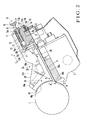
- Fig. 2 shows an ink fountain apparatus for a rotary printing press according to an embodiment of the present invention.
- an ink fountain roller 1 rotatable in the direction of an arrow A axially extends between a pair of frames (not shown) arranged to oppose each other through a predetermined distance, and a blade base 2 is provided beside the ink fountain roller 1 such that its two ends are supported by the pair of frames.
- a large number of ink fountain keys 3 divided in the axial direction of the ink fountain roller 1 are placed on a slant surface at the upper end of the blade base 2.
- a motor (not shown) is driven, the aperture ratios of the distal ends of the ink fountain keys 3 are adjusted in directions to become close to and away from the outer surface of the ink fountain roller 1.
- One ink fountain blade 4 formed of a thin steel plate to serve as a bottom plate is magnetically attracted so it comes into tight contact with the ink fountain key 3 to cover the large number of ink fountain keys 3.
- a pair of opposing ink dams 5 arranged to correspond to the two ends of the ink fountain roller 1 are fixed to a member (not shown) swingably supported between the frames, such that the inner surfaces of their distal ends are pressed by the two end faces of the ink fountain roller 1.
- the pair of ink dams 5 standing upright from the ink fountain blade 4, the outer surface of the ink fountain roller 1, and the ink fountain blade 4 make up a tub-like ink fountain 6.
- a bar 8 extending in the axial direction of the ink fountain roller 1 behind the ink fountain 6 has two ends fixed to the member (not shown) swingably supported between the frames.
- a thin-plate-like rectangular parallelepiped holder 10 has a fitting groove 11 with a U-shaped section to communicate with its upper end and its side surface on the ink fountain roller 1 side, and a notch 12, extending in the axial direction of the ink fountain roller 1, in its lower end.
- the notch 12 is slightly larger than the sectional area of the bar 8.
- a blind hole-like spring accommodating hole 13 is formed in the upper portion of the holder 10.
- a threaded portion 13a is formed at the inlet port of the spring accommodating hole 13, and a small-diameter insertion hole 13b is formed in the spring accommodating hole 13 to reach its bottom.
- a screw hole 14 with a screw portion extending to reach a recess 8a of the bar 8 is formed in the lower portion of the holder 10.
- an operation rod 15 serving as a thin, elongated press member has a spring accepting portion 15a, with a diameter slightly smaller than the diameter of the spring accommodating hole 13, at its distal end.
- a press shaft portion 15b with a diameter slightly smaller than the diameter of the insertion hole 13b projects from one end of the spring accepting portion 15a toward the ink fountain roller 1.
- a handle member 16 is fixed to the proximal end (counter distal end) of the operation rod 15.
- a screw 17 has a screw portion 17a threadably engageable with the threaded portion 13a of the spring accommodating hole 13, and an insertion hole 17b with a diameter slightly larger than the diameter of the operation rod 15 is formed at the center of the screw 17.
- a compression coil spring 18 serving as a biasing means is elastically mounted between the spring accepting portion 15a of the operation rod 15 inserted in the spring accommodating hole 13 and the screw 17 with the screw portion 17a threadably engaging with the threaded portion 13a.
- the press shaft portion 15b of the operation rod 15 in the insertion hole 13b is then biased from the holder 10 in a direction to become close to the ink fountain roller 1.
- a set screw 19 threadably engages with the screw hole 14 of the holder 10 and serves to fix the holder 10 to the bar 8.
- a nut 20 threadably engages with the set screw 19 and serves to regulate forward/backward movement of the set screw 19.
- each intermediate ink dam 25 is comprised of an operation plate (third member) 26, a pair of sandwiching plates 27 and 28 for sandwiching the operation plate 26 from two sides, an adjustment plate (second member) 29 in contact opposite to the lower surface of the operation plate 26, and a press plate (first member) 30 having an upper end face in contact opposite to the lower surface of the adjustment plate 29.
- the press plate 30 is arranged in the same planar direction as those of the operation plate 26 and sandwiching plates 27 and 28.
- the operation plate 26 is formed of a horizontal portion 26a extending in a direction perpendicular to the axial direction of the ink fountain roller 1 and an upright portion 26b extending obliquely upward from the distal end of the horizontal portion 26a, to have a substantial L shape.
- a substantially L-shaped support 31 is integrally formed at the front end of the horizontal portion 26a to be thicker than the horizontal portion 26a because of steps 31a.
- the horizontal portion of the support 31 is fitted in the fitting groove 11 of the holder 10, and part of the vertical portion of the support 31 forms an engaging surface 31b formed of a slant surface. As shown in Fig. 2, the slanting direction of the engaging surface 31b is set such that an angle ⁇ formed by the upper surface of the ink fountain blade 4 and the extension of the slant surface of the engaging surface 31b is an acute angle.
- the operation plate 26 has, in its the horizontal portion 26a and upright portion 26b, a total of five insertion holes 32 and a total of five screw holes 33.
- Three adjustment bolts 34a, 34b, and 34c threadably engage with screw holes formed at the upper and lower portions of the upright portion 26b and the substantial center of the horizontal portion 26a of the operation plate 26.
- the adjustment bolt 34b attached to the lower portion of the upright portion 26b moves forward/backward (in the direction indicated by an arrow D) toward a point B where the outer surface of the ink fountain roller 1 and the ink fountain key 3 oppose each other.
- the sandwiching plate 27 has five screw holes 36 corresponding to the insertion holes 32 of the operation plate 26.
- the sandwiching plate 28 has five insertion holes 37 with spot-faced upper surfaces to correspond to the insertion holes 32 of the operation plate 26, and five insertion holes 38 corresponding to the screw holes 33.
- the adjustment plate 29 is formed by bending a thin steel plate with spring properties into a substantial L shape.
- the adjustment plate 29 is comprised of a horizontal portion 29a in contact opposite to the lower surface of the horizontal portion 26a of the operation plate 26, and an upright portion 29b in contact opposite to the rear end face of the upright portion 26b.
- the press plate 30 standing upright in contact with the lower surface of the adjustment plate 29 is made of polyvinyl chloride as an elastic material with an overall wear resistance into a substantial L shape.
- the press plate 30 is comprised of a horizontal portion 39 with an upper end face in contact opposite to the horizontal portion 29a of the adjustment plate 29, and an upright portion 40 with a front end face in contact opposite to the upright portion 29b of the adjustment plate 29.
- the lower end face of the horizontal portion 39 of the press plate 30 serves as a linear blade press portion 39a for pressing the blade 4, and the rear end face of the upright portion 40 serves as an arcuate ink fountain press portion 40a for pressing the outer surface of the ink fountain roller 1.
- the width of the adjustment plate 29 and the plate thickness of the press plate 30 are almost the same, and are slightly smaller than the thicknesses of the horizontal portion 26a and upright portion 26b of the operation plate 26.
- the blade press portion 39a and ink fountain press portion 40a of the press plate 30 project from the lower and rear ends, respectively, of each of the sandwiching plates 27 and 28.
- the elastic force of the compression coil spring 18 biases the operation rod 15 in a direction indicated by the arrow E to become close to the ink fountain roller 1, and the distal end of the press shaft portion 15b projecting from the insertion hole 13b abuts against the engaging surface 31b of the support 31. Since the engaging surface 31b is formed in such a direction that the angle ⁇ formed by the ink fountain blade 4 and the extension of the slant surface 31b is an acute angle, the press direction with respect to the press plate 30 changes as indicated by an arrow C.
- the press plate 30 is pressed almost toward the point B where the outer surface of the ink fountain roller 1 and the ink fountain key 3 oppose each other. Therefore, the blade press portion 39a and ink fountain press portion 40a of the press plate 30 respectively press the ink fountain blade 4 and the outer surface of the ink fountain roller 1, and accordingly the blade press portion 39a and ink fountain press portion 40a come into tight contact with the ink fountain blade 4 and the outer surface of the ink fountain roller 1, respectively.
- the press plate 30 since the operation plate 26 presses the press plate 30 through the thin plate-like adjustment plate 29, the press plate 30 is pressed uniformly and will not be locally fractured. Since the adjustment plate 29 is made of an elastic material, local elastic deformation of the press plate 30 can be prevented, so the tight contact force becomes uniform throughout the press plate 30.
- the threadable engagement amounts of the adjustment bolts 34a, 34b, and 34c are adjusted separately, to adjust the tight contact partly.
- the threadable engagement amount of the adjustment bolt 34b which moves forward/backward with respect to the point B where the outer surface of the ink fountain roller 1 and the ink fountain keys 3 oppose each other, is adjusted, the tight contact between the blade press portion 39a and ink fountain blade 4 and that between the ink fountain press portion 40a and the outer surface of the ink fountain roller 1 can be adjusted simultaneously.
- the tight contact state of the press plate 30 can be partly adjusted, so partial outflow of the ink can be prevented.
- the amount of ink consumed can be reduced, and the printing quality of rainbow printing can be improved.
- the press plate 30 is made of the elastic material, when the press state is to be partly adjusted, partial deformation of the press plate 30 due to the adjustment bolts 34a to 34c can be prevented.
- a projection 39b for pressing the upper surface of the distal end of the corresponding ink fountain key 3 is formed at the distal end of the blade press portion 39a of the press plate 30. Since the projection 39b locally presses the upper surface of the distal end of the ink fountain key 3, the tight contact of the press plate 30 is further improved, and the ink from the ink fountain roller 1 is prevented from entering a portion between the blade press portion 39a and ink fountain blade 4, through the blade press portion 39a and the ink fountain key 3. As a result, ink to be used for subsequent printing is prevented from mixing with printing ink used previously. Also, the ink fountain key 3 is prevented from causing an operation error because the entering ink solidifies.
- the press plate 30 is made of the wear-resistant elastic material, wear of the press plate 30 at its portion in contact opposite to the ink fountain roller 1 and that in contact opposite to the ink fountain blade 4 are reduced. Also, the tight contact of the press plate 30 at its portion in contact opposite to the ink fountain roller 1 and that in contact opposite to the ink fountain blade 4 are improved.
- the operator holds the holding member 16, and moves the operation rod 15 against the elastic force of the compression coil spring 18 in a direction to separate it away from the ink fountain roller 1. Then, the operator releases the engaging surface 31b which has been pressed by the press shaft portion 15b, and removes the operation rod 15 from the holder 10. In this manner, the intermediate ink dam 25 can be mounted and detached by merely moving the operation rod 15 against the elastic force of the compression coil spring 18 without requiring a tool. Thus, the intermediate ink dams 25 can be mounted and detached easily.
- the press plate 30 is made of polyvinyl chloride.
- the present invention is not limited to this, but the press plate 30 can be made of any elastic material as far as it has wear resistance.
- the tight contact state between the intermediate ink dam and blade and that between the intermediate ink dam and the outer surface of the ink fountain roller are partially adjusted, so the tight contact force is improved and partial outflow of the ink can be prevented. Therefore, the amount of ink consumed is reduced, and the printing quality of rainbow printing is improved.
Landscapes
- Inking, Control Or Cleaning Of Printing Machines (AREA)
- Toys (AREA)
- Moulding By Coating Moulds (AREA)
- Refrigerator Housings (AREA)
Abstract
Description
Claims (10)
- An ink fountain apparatus for a rotary printing press, characterized by comprising:a rotatably supported ink fountain roller (1);an ink fountain (6) comprised of a bottom plate (4) with one end supported close to said ink fountain roller and a pair of ink dams (5) standing upright from said bottom plate to correspond to two ends of said ink fountain roller and arranged to oppose in an axial direction of said ink fountain roller;at least one intermediate ink dam (25) standing upright between said ink dams from said bottom plate, said intermediate ink dam including a first member (30) in contact opposite to an outer surface of said ink fountain roller and said bottom plate, a second member (29) in contact opposite to said first member, and a third member (26) in contact opposite to said second member;press means (18, 15, 15b, 31b) for pressing said first member through said third and second members toward the outer surface of said ink fountain roller and toward said bottom plate; andan adjustment tool (34a - 34c) for adjusting a tight contact state of said first member with respect to at least one of the outer surface of said ink fountain roller and said bottom plate.
- An apparatus according to claim 1, wherein said first member is made of a wear-resistant elastic material.
- An apparatus according to claim 1, whereinsaid first member is a plate-like member arranged in a direction perpendicular to the axial direction of said ink fountain roller and with one end faces that press the outer surface of said ink fountain roller and said bottom plate,said third member is a plate-like member arranged in a direction perpendicular to the axial direction of said ink fountain roller and with one end face that presses said second member by press operation of said press means, andsaid second member is a thin plate-like member arranged between the other end face of said first member and one end face of said third member.
- An apparatus according to claim 3, wherein the thin plate-like member serving as said second member is made of a thin steel plate with spring properties.
- An apparatus according to claim 1, wherein said adjustment tool adjusts said first member substantially in a direction toward a position where the outer surface of said ink fountain roller and said bottom plate oppose each other.
- An apparatus according to claim 1, further comprisingan ink fountain key (3) supported by a lower surface of the bottom plate and with a distal end projecting toward said ink fountain roller closer than a distal end of said bottom plate, anda projection (39b) projecting from a press surface of said first member and in contact with an upper face of the projecting distal end of said fountain key.
- An apparatus according to claim 1, whereinsaid third member has an engaging surface (31b) formed of a slant surface, andsaid press means comprises an operation rod (15) biased in a direction to become close to said ink fountain roller and with a distal end engageable with the engaging surface.
- An apparatus according to claim 7, further comprisinga support (31) formed integrally with said third member and having the engaging surface,a holder (10) for supporting said support to be movable in a direction to become close to and away from said ink fountain roller, andan operating portion (16) formed integrally with said operation rod and adapted to release the distal end of said operation rod from the engaging surface against a biasing force.
- An apparatus according to claim 8, further comprisinga support bar (8) for supporting said holder to be movable in the axial direction of said ink fountain roller, anda fixing mechanism (19, 20) for fixing/releasing said holder to/from said support bar.
- An apparatus according to claim 1, wherein said press means comprisesa holder (10) with a first through hole (13b) and adapted to support said intermediate ink dam to be movable in a direction to become close to and away from said ink fountain roller,a rod-like press member (15) supported in the first through hole to be movable in a moving direction of said intermediate ink dam and with a distal end (15b) projecting from one end of the first through hole to abut against said third member, said press member having a spring accepting portion (15a),a screw (17) with a second through hole (17b) in which said press member extends and threadably engageable with the other end of the first through hole, anda spring (18) mounted between the spring accepting portion and said screw and adapted to bias the distal end of said press member to press said third member,said spring having a biasing force adjusted by pivot motion of said screw.
Priority Applications (1)
| Application Number | Priority Date | Filing Date | Title |
|---|---|---|---|
| EP07013305A EP1834777A3 (en) | 2000-06-30 | 2001-06-26 | Ink fountain apparatus for rotary printing press |
Applications Claiming Priority (2)
| Application Number | Priority Date | Filing Date | Title |
|---|---|---|---|
| JP2000198698A JP4527247B2 (en) | 2000-06-30 | 2000-06-30 | Ink fountain device for rotary printing press |
| JP2000198698 | 2000-06-30 |
Related Child Applications (1)
| Application Number | Title | Priority Date | Filing Date |
|---|---|---|---|
| EP07013305A Division EP1834777A3 (en) | 2000-06-30 | 2001-06-26 | Ink fountain apparatus for rotary printing press |
Publications (3)
| Publication Number | Publication Date |
|---|---|
| EP1167032A2 true EP1167032A2 (en) | 2002-01-02 |
| EP1167032A3 EP1167032A3 (en) | 2004-02-11 |
| EP1167032B1 EP1167032B1 (en) | 2007-09-26 |
Family
ID=18696825
Family Applications (2)
| Application Number | Title | Priority Date | Filing Date |
|---|---|---|---|
| EP01115388A Expired - Lifetime EP1167032B1 (en) | 2000-06-30 | 2001-06-26 | Ink fountain apparatus for rotary printing press |
| EP07013305A Withdrawn EP1834777A3 (en) | 2000-06-30 | 2001-06-26 | Ink fountain apparatus for rotary printing press |
Family Applications After (1)
| Application Number | Title | Priority Date | Filing Date |
|---|---|---|---|
| EP07013305A Withdrawn EP1834777A3 (en) | 2000-06-30 | 2001-06-26 | Ink fountain apparatus for rotary printing press |
Country Status (6)
| Country | Link |
|---|---|
| US (1) | US6772684B2 (en) |
| EP (2) | EP1167032B1 (en) |
| JP (1) | JP4527247B2 (en) |
| AT (1) | ATE374107T1 (en) |
| DE (1) | DE60130606T2 (en) |
| ES (1) | ES2293948T3 (en) |
Cited By (4)
| Publication number | Priority date | Publication date | Assignee | Title |
|---|---|---|---|---|
| EP1533118A1 (en) * | 2003-11-19 | 2005-05-25 | Komori Corporation | Ink fountain apparatus for rotary printing press |
| DE102009005291A1 (en) | 2008-02-08 | 2009-08-13 | Heidelberger Druckmaschinen Ag | Method for setting up a color box of a printing machine |
| CN101954784A (en) * | 2009-07-20 | 2011-01-26 | 海德堡印刷机械股份公司 | The dosing mechanism of the ink fountain of printing machine |
| CN102862384A (en) * | 2011-07-06 | 2013-01-09 | 海德堡印刷机械股份公司 | Method for operating anilox printing unit and printing press with anilox printing unit |
Families Citing this family (5)
| Publication number | Priority date | Publication date | Assignee | Title |
|---|---|---|---|---|
| ITGE20030044A1 (en) * | 2003-06-25 | 2004-12-26 | Schiavi Spa | SIDE SEALING DEVICE FOR ROOMS IN RACLE DI |
| JP4373147B2 (en) * | 2003-07-17 | 2009-11-25 | 株式会社小森コーポレーション | Ink fountain device for printing machine |
| JP3976727B2 (en) * | 2003-12-08 | 2007-09-19 | リョービ株式会社 | Ink kneading method of printing machine and printing machine |
| JP2005193508A (en) * | 2004-01-07 | 2005-07-21 | Komori Corp | Ink fountain device for printing machine |
| CN107081975B (en) * | 2017-05-27 | 2019-02-26 | 上海安全印务有限公司 | A kind of smart card face undertone high-precision intersects the anti-fake processing technology of rainbow |
Family Cites Families (14)
| Publication number | Priority date | Publication date | Assignee | Title |
|---|---|---|---|---|
| US1890922A (en) * | 1929-04-13 | 1932-12-13 | Edward A Waller | Multicolor printing press |
| US1893148A (en) * | 1931-02-16 | 1933-01-03 | Robert R Page | Articulated fountain divider |
| US1919283A (en) * | 1931-12-22 | 1933-07-25 | Martin J Troy | Ink fountain divider and pad |
| US1953105A (en) * | 1933-07-31 | 1934-04-03 | George H Flinker | Fountain divider for printing presses |
| US2301535A (en) * | 1941-12-09 | 1942-11-10 | Meredith Publishing Company | Fountain divider |
| US2514633A (en) * | 1946-05-07 | 1950-07-11 | Western Electric Co | Variable-density push-pull sound recording system |
| US2514653A (en) * | 1949-05-02 | 1950-07-11 | Stephen A Lerch | Ink fountain divider |
| US2920558A (en) * | 1953-10-09 | 1960-01-12 | Dayton Rubber Company | Fountain dividers |
| US3319563A (en) * | 1964-09-18 | 1967-05-16 | Clarence M Champion | Ink separator |
| DE8034726U1 (en) * | 1980-12-29 | 1981-05-27 | M.A.N.- Roland Druckmaschinen AG, 6050 Offenbach | DEVICE FOR SEPARATING AREAS OF COLOR APPLICATION ON INK BOXES FOR PRINTING MACHINES |
| JPH0646675Y2 (en) * | 1987-05-27 | 1994-11-30 | 株式会社小森コーポレーション | Inkwell device of printing machine |
| US4991504A (en) * | 1988-12-15 | 1991-02-12 | De La Rue Giori S.A. | Ink duct for a printing machine |
| JPH0747099Y2 (en) | 1992-12-08 | 1995-11-01 | 株式会社羽島 | Sewing presser foot |
| JP3254575B2 (en) * | 1997-05-15 | 2002-02-12 | 株式会社東京機械製作所 | Ink divider for ink fountain device |
-
2000
- 2000-06-30 JP JP2000198698A patent/JP4527247B2/en not_active Expired - Fee Related
-
2001
- 2001-06-26 AT AT01115388T patent/ATE374107T1/en not_active IP Right Cessation
- 2001-06-26 DE DE60130606T patent/DE60130606T2/en not_active Expired - Lifetime
- 2001-06-26 EP EP01115388A patent/EP1167032B1/en not_active Expired - Lifetime
- 2001-06-26 ES ES01115388T patent/ES2293948T3/en not_active Expired - Lifetime
- 2001-06-26 EP EP07013305A patent/EP1834777A3/en not_active Withdrawn
- 2001-06-29 US US09/895,622 patent/US6772684B2/en not_active Expired - Fee Related
Cited By (7)
| Publication number | Priority date | Publication date | Assignee | Title |
|---|---|---|---|---|
| EP1533118A1 (en) * | 2003-11-19 | 2005-05-25 | Komori Corporation | Ink fountain apparatus for rotary printing press |
| US7096786B2 (en) | 2003-11-19 | 2006-08-29 | Komori Corporation | Ink fountain apparatus for rotary printing press |
| DE102009005291A1 (en) | 2008-02-08 | 2009-08-13 | Heidelberger Druckmaschinen Ag | Method for setting up a color box of a printing machine |
| US8695499B2 (en) | 2008-02-08 | 2014-04-15 | Heidelberger Druckmaschinen Ag | Method for setting up an ink fountain of a printing press and printing press having an ink fountain |
| CN101954784A (en) * | 2009-07-20 | 2011-01-26 | 海德堡印刷机械股份公司 | The dosing mechanism of the ink fountain of printing machine |
| CN101954784B (en) * | 2009-07-20 | 2014-01-01 | 海德堡印刷机械股份公司 | Dosing device of printing press and ink fountain |
| CN102862384A (en) * | 2011-07-06 | 2013-01-09 | 海德堡印刷机械股份公司 | Method for operating anilox printing unit and printing press with anilox printing unit |
Also Published As
| Publication number | Publication date |
|---|---|
| ES2293948T3 (en) | 2008-04-01 |
| EP1834777A3 (en) | 2008-09-17 |
| DE60130606D1 (en) | 2007-11-08 |
| JP2002011851A (en) | 2002-01-15 |
| JP4527247B2 (en) | 2010-08-18 |
| EP1834777A2 (en) | 2007-09-19 |
| US6772684B2 (en) | 2004-08-10 |
| US20030164104A1 (en) | 2003-09-04 |
| DE60130606T2 (en) | 2008-06-26 |
| EP1167032B1 (en) | 2007-09-26 |
| ATE374107T1 (en) | 2007-10-15 |
| EP1167032A3 (en) | 2004-02-11 |
Similar Documents
| Publication | Publication Date | Title |
|---|---|---|
| EP1167032B1 (en) | Ink fountain apparatus for rotary printing press | |
| KR100732917B1 (en) | Semi-automatic screen printing machine | |
| EP0635363B1 (en) | Inking arrangement for printing presses | |
| EP1533118B1 (en) | Ink fountain apparatus for rotary printing press | |
| JP2008100524A (en) | Scraping blade for printing press | |
| US4413561A (en) | Ink fountain devices for printing press | |
| US7117791B2 (en) | Ink fountain apparatus for printing press | |
| US3658002A (en) | Clamping device for clamping a printing plate upon a cylinder of a printing press | |
| JP2529486Y2 (en) | Head press mechanism of thermal printer | |
| JP3866350B2 (en) | Thermal head support device for thermal printer | |
| EP0945269B1 (en) | Inking device | |
| JP2959730B2 (en) | Doctor device | |
| JP2917251B2 (en) | Inkwell | |
| US6405649B1 (en) | Ink fountain blade for a printing machine | |
| US20090174132A1 (en) | Label sheet positioning device of barcode printer | |
| JP3487835B2 (en) | Ink fountain blade adjustment device for printing press | |
| JP2882853B2 (en) | Printer head gap adjustment device | |
| US6378422B1 (en) | Rotary marking device | |
| US20030099499A1 (en) | Registration cam for a printing press | |
| KR200301529Y1 (en) | Structure for establishing shaft squeeze blade used in printing machine | |
| JPH037159Y2 (en) | ||
| KR200366807Y1 (en) | Camera Control Apparatus for Register Punching Machine | |
| JP5246557B2 (en) | Cylinder cleaning device | |
| JP2007185858A (en) | Nip adjusting equipment for water source roller | |
| JPH0149624B2 (en) |
Legal Events
| Date | Code | Title | Description |
|---|---|---|---|
| PUAI | Public reference made under article 153(3) epc to a published international application that has entered the european phase |
Free format text: ORIGINAL CODE: 0009012 |
|
| AK | Designated contracting states |
Kind code of ref document: A2 Designated state(s): AT BE CH CY DE DK ES FI FR GB GR IE IT LI LU MC NL PT SE TR |
|
| AX | Request for extension of the european patent |
Free format text: AL;LT;LV;MK;RO;SI |
|
| PUAL | Search report despatched |
Free format text: ORIGINAL CODE: 0009013 |
|
| AK | Designated contracting states |
Kind code of ref document: A3 Designated state(s): AT BE CH CY DE DK ES FI FR GB GR IE IT LI LU MC NL PT SE TR |
|
| AX | Request for extension of the european patent |
Extension state: AL LT LV MK RO SI |
|
| RIC1 | Information provided on ipc code assigned before grant |
Ipc: 7B 41F 31/18 B Ipc: 7B 41F 31/02 A |
|
| 17P | Request for examination filed |
Effective date: 20040712 |
|
| AKX | Designation fees paid |
Designated state(s): AT BE CH CY DE DK ES FI FR GB GR IE IT LI LU MC NL PT SE TR |
|
| GRAP | Despatch of communication of intention to grant a patent |
Free format text: ORIGINAL CODE: EPIDOSNIGR1 |
|
| GRAS | Grant fee paid |
Free format text: ORIGINAL CODE: EPIDOSNIGR3 |
|
| GRAA | (expected) grant |
Free format text: ORIGINAL CODE: 0009210 |
|
| AK | Designated contracting states |
Kind code of ref document: B1 Designated state(s): AT BE CH CY DE DK ES FI FR GB GR IE IT LI LU MC NL PT SE TR |
|
| REG | Reference to a national code |
Ref country code: GB Ref legal event code: FG4D |
|
| REG | Reference to a national code |
Ref country code: CH Ref legal event code: EP |
|
| REF | Corresponds to: |
Ref document number: 60130606 Country of ref document: DE Date of ref document: 20071108 Kind code of ref document: P |
|
| REG | Reference to a national code |
Ref country code: IE Ref legal event code: FG4D |
|
| REG | Reference to a national code |
Ref country code: CH Ref legal event code: NV Representative=s name: LUCHS & PARTNER PATENTANWAELTE |
|
| REG | Reference to a national code |
Ref country code: SE Ref legal event code: TRGR |
|
| PG25 | Lapsed in a contracting state [announced via postgrant information from national office to epo] |
Ref country code: FI Free format text: LAPSE BECAUSE OF FAILURE TO SUBMIT A TRANSLATION OF THE DESCRIPTION OR TO PAY THE FEE WITHIN THE PRESCRIBED TIME-LIMIT Effective date: 20070926 |
|
| ET | Fr: translation filed | ||
| PG25 | Lapsed in a contracting state [announced via postgrant information from national office to epo] |
Ref country code: AT Free format text: LAPSE BECAUSE OF FAILURE TO SUBMIT A TRANSLATION OF THE DESCRIPTION OR TO PAY THE FEE WITHIN THE PRESCRIBED TIME-LIMIT Effective date: 20070926 |
|
| PG25 | Lapsed in a contracting state [announced via postgrant information from national office to epo] |
Ref country code: BE Free format text: LAPSE BECAUSE OF FAILURE TO SUBMIT A TRANSLATION OF THE DESCRIPTION OR TO PAY THE FEE WITHIN THE PRESCRIBED TIME-LIMIT Effective date: 20070926 |
|
| REG | Reference to a national code |
Ref country code: ES Ref legal event code: FG2A Ref document number: 2293948 Country of ref document: ES Kind code of ref document: T3 |
|
| PG25 | Lapsed in a contracting state [announced via postgrant information from national office to epo] |
Ref country code: GR Free format text: LAPSE BECAUSE OF FAILURE TO SUBMIT A TRANSLATION OF THE DESCRIPTION OR TO PAY THE FEE WITHIN THE PRESCRIBED TIME-LIMIT Effective date: 20071227 |
|
| PG25 | Lapsed in a contracting state [announced via postgrant information from national office to epo] |
Ref country code: PT Free format text: LAPSE BECAUSE OF FAILURE TO SUBMIT A TRANSLATION OF THE DESCRIPTION OR TO PAY THE FEE WITHIN THE PRESCRIBED TIME-LIMIT Effective date: 20080226 |
|
| PG25 | Lapsed in a contracting state [announced via postgrant information from national office to epo] |
Ref country code: DK Free format text: LAPSE BECAUSE OF FAILURE TO SUBMIT A TRANSLATION OF THE DESCRIPTION OR TO PAY THE FEE WITHIN THE PRESCRIBED TIME-LIMIT Effective date: 20070926 |
|
| PLBE | No opposition filed within time limit |
Free format text: ORIGINAL CODE: 0009261 |
|
| STAA | Information on the status of an ep patent application or granted ep patent |
Free format text: STATUS: NO OPPOSITION FILED WITHIN TIME LIMIT |
|
| 26N | No opposition filed |
Effective date: 20080627 |
|
| PG25 | Lapsed in a contracting state [announced via postgrant information from national office to epo] |
Ref country code: MC Free format text: LAPSE BECAUSE OF NON-PAYMENT OF DUE FEES Effective date: 20080630 |
|
| PG25 | Lapsed in a contracting state [announced via postgrant information from national office to epo] |
Ref country code: IE Free format text: LAPSE BECAUSE OF NON-PAYMENT OF DUE FEES Effective date: 20080626 |
|
| PG25 | Lapsed in a contracting state [announced via postgrant information from national office to epo] |
Ref country code: CY Free format text: LAPSE BECAUSE OF FAILURE TO SUBMIT A TRANSLATION OF THE DESCRIPTION OR TO PAY THE FEE WITHIN THE PRESCRIBED TIME-LIMIT Effective date: 20070926 |
|
| PGFP | Annual fee paid to national office [announced via postgrant information from national office to epo] |
Ref country code: NL Payment date: 20090615 Year of fee payment: 9 |
|
| PGFP | Annual fee paid to national office [announced via postgrant information from national office to epo] |
Ref country code: IT Payment date: 20090622 Year of fee payment: 9 Ref country code: SE Payment date: 20090605 Year of fee payment: 9 |
|
| PGFP | Annual fee paid to national office [announced via postgrant information from national office to epo] |
Ref country code: ES Payment date: 20090710 Year of fee payment: 9 |
|
| PGFP | Annual fee paid to national office [announced via postgrant information from national office to epo] |
Ref country code: GB Payment date: 20090624 Year of fee payment: 9 |
|
| PG25 | Lapsed in a contracting state [announced via postgrant information from national office to epo] |
Ref country code: LU Free format text: LAPSE BECAUSE OF NON-PAYMENT OF DUE FEES Effective date: 20080626 |
|
| PG25 | Lapsed in a contracting state [announced via postgrant information from national office to epo] |
Ref country code: TR Free format text: LAPSE BECAUSE OF FAILURE TO SUBMIT A TRANSLATION OF THE DESCRIPTION OR TO PAY THE FEE WITHIN THE PRESCRIBED TIME-LIMIT Effective date: 20070926 |
|
| REG | Reference to a national code |
Ref country code: NL Ref legal event code: V1 Effective date: 20110101 |
|
| EUG | Se: european patent has lapsed | ||
| GBPC | Gb: european patent ceased through non-payment of renewal fee |
Effective date: 20100626 |
|
| REG | Reference to a national code |
Ref country code: FR Ref legal event code: ST Effective date: 20110228 |
|
| PG25 | Lapsed in a contracting state [announced via postgrant information from national office to epo] |
Ref country code: IT Free format text: LAPSE BECAUSE OF NON-PAYMENT OF DUE FEES Effective date: 20100626 |
|
| PG25 | Lapsed in a contracting state [announced via postgrant information from national office to epo] |
Ref country code: FR Free format text: LAPSE BECAUSE OF NON-PAYMENT OF DUE FEES Effective date: 20100630 Ref country code: NL Free format text: LAPSE BECAUSE OF NON-PAYMENT OF DUE FEES Effective date: 20110101 |
|
| REG | Reference to a national code |
Ref country code: ES Ref legal event code: FD2A Effective date: 20110714 |
|
| PG25 | Lapsed in a contracting state [announced via postgrant information from national office to epo] |
Ref country code: ES Free format text: LAPSE BECAUSE OF NON-PAYMENT OF DUE FEES Effective date: 20110704 Ref country code: GB Free format text: LAPSE BECAUSE OF NON-PAYMENT OF DUE FEES Effective date: 20100626 |
|
| PG25 | Lapsed in a contracting state [announced via postgrant information from national office to epo] |
Ref country code: ES Free format text: LAPSE BECAUSE OF NON-PAYMENT OF DUE FEES Effective date: 20100627 |
|
| PGFP | Annual fee paid to national office [announced via postgrant information from national office to epo] |
Ref country code: DE Payment date: 20120620 Year of fee payment: 12 Ref country code: CH Payment date: 20120612 Year of fee payment: 12 |
|
| PG25 | Lapsed in a contracting state [announced via postgrant information from national office to epo] |
Ref country code: SE Free format text: LAPSE BECAUSE OF NON-PAYMENT OF DUE FEES Effective date: 20100627 |
|
| PGFP | Annual fee paid to national office [announced via postgrant information from national office to epo] |
Ref country code: FR Payment date: 20090611 Year of fee payment: 9 |
|
| REG | Reference to a national code |
Ref country code: CH Ref legal event code: PL |
|
| REG | Reference to a national code |
Ref country code: DE Ref legal event code: R119 Ref document number: 60130606 Country of ref document: DE Effective date: 20140101 |
|
| PG25 | Lapsed in a contracting state [announced via postgrant information from national office to epo] |
Ref country code: LI Free format text: LAPSE BECAUSE OF NON-PAYMENT OF DUE FEES Effective date: 20130630 Ref country code: DE Free format text: LAPSE BECAUSE OF NON-PAYMENT OF DUE FEES Effective date: 20140101 Ref country code: CH Free format text: LAPSE BECAUSE OF NON-PAYMENT OF DUE FEES Effective date: 20130630 |