EP1166955A2 - System for attaching / detaching a workpiece to be machined on a jig - Google Patents
System for attaching / detaching a workpiece to be machined on a jig Download PDFInfo
- Publication number
- EP1166955A2 EP1166955A2 EP01305501A EP01305501A EP1166955A2 EP 1166955 A2 EP1166955 A2 EP 1166955A2 EP 01305501 A EP01305501 A EP 01305501A EP 01305501 A EP01305501 A EP 01305501A EP 1166955 A2 EP1166955 A2 EP 1166955A2
- Authority
- EP
- European Patent Office
- Prior art keywords
- workpiece
- jig
- machined
- robot
- pull bolt
- Prior art date
- Legal status (The legal status is an assumption and is not a legal conclusion. Google has not performed a legal analysis and makes no representation as to the accuracy of the status listed.)
- Granted
Links
- 230000007246 mechanism Effects 0.000 claims description 21
- 210000000707 wrist Anatomy 0.000 abstract description 15
- 238000003754 machining Methods 0.000 description 22
- 230000033001 locomotion Effects 0.000 description 9
- 230000005540 biological transmission Effects 0.000 description 7
- 230000004044 response Effects 0.000 description 6
- 238000000034 method Methods 0.000 description 5
- 230000008859 change Effects 0.000 description 4
- 230000008569 process Effects 0.000 description 3
- 238000003825 pressing Methods 0.000 description 2
- 230000009471 action Effects 0.000 description 1
- 238000010586 diagram Methods 0.000 description 1
- 230000000694 effects Effects 0.000 description 1
- 238000003780 insertion Methods 0.000 description 1
- 230000037431 insertion Effects 0.000 description 1
Images





Classifications
-
- B—PERFORMING OPERATIONS; TRANSPORTING
- B23—MACHINE TOOLS; METAL-WORKING NOT OTHERWISE PROVIDED FOR
- B23Q—DETAILS, COMPONENTS, OR ACCESSORIES FOR MACHINE TOOLS, e.g. ARRANGEMENTS FOR COPYING OR CONTROLLING; MACHINE TOOLS IN GENERAL CHARACTERISED BY THE CONSTRUCTION OF PARTICULAR DETAILS OR COMPONENTS; COMBINATIONS OR ASSOCIATIONS OF METAL-WORKING MACHINES, NOT DIRECTED TO A PARTICULAR RESULT
- B23Q1/00—Members which are comprised in the general build-up of a form of machine, particularly relatively large fixed members
- B23Q1/25—Movable or adjustable work or tool supports
- B23Q1/64—Movable or adjustable work or tool supports characterised by the purpose of the movement
- B23Q1/66—Worktables interchangeably movable into operating positions
-
- B—PERFORMING OPERATIONS; TRANSPORTING
- B23—MACHINE TOOLS; METAL-WORKING NOT OTHERWISE PROVIDED FOR
- B23Q—DETAILS, COMPONENTS, OR ACCESSORIES FOR MACHINE TOOLS, e.g. ARRANGEMENTS FOR COPYING OR CONTROLLING; MACHINE TOOLS IN GENERAL CHARACTERISED BY THE CONSTRUCTION OF PARTICULAR DETAILS OR COMPONENTS; COMBINATIONS OR ASSOCIATIONS OF METAL-WORKING MACHINES, NOT DIRECTED TO A PARTICULAR RESULT
- B23Q3/00—Devices holding, supporting, or positioning work or tools, of a kind normally removable from the machine
- B23Q3/02—Devices holding, supporting, or positioning work or tools, of a kind normally removable from the machine for mounting on a work-table, tool-slide, or analogous part
- B23Q3/04—Devices holding, supporting, or positioning work or tools, of a kind normally removable from the machine for mounting on a work-table, tool-slide, or analogous part adjustable in inclination
-
- Y—GENERAL TAGGING OF NEW TECHNOLOGICAL DEVELOPMENTS; GENERAL TAGGING OF CROSS-SECTIONAL TECHNOLOGIES SPANNING OVER SEVERAL SECTIONS OF THE IPC; TECHNICAL SUBJECTS COVERED BY FORMER USPC CROSS-REFERENCE ART COLLECTIONS [XRACs] AND DIGESTS
- Y10—TECHNICAL SUBJECTS COVERED BY FORMER USPC
- Y10T—TECHNICAL SUBJECTS COVERED BY FORMER US CLASSIFICATION
- Y10T29/00—Metal working
- Y10T29/49—Method of mechanical manufacture
- Y10T29/4981—Utilizing transitory attached element or associated separate material
-
- Y—GENERAL TAGGING OF NEW TECHNOLOGICAL DEVELOPMENTS; GENERAL TAGGING OF CROSS-SECTIONAL TECHNOLOGIES SPANNING OVER SEVERAL SECTIONS OF THE IPC; TECHNICAL SUBJECTS COVERED BY FORMER USPC CROSS-REFERENCE ART COLLECTIONS [XRACs] AND DIGESTS
- Y10—TECHNICAL SUBJECTS COVERED BY FORMER USPC
- Y10T—TECHNICAL SUBJECTS COVERED BY FORMER US CLASSIFICATION
- Y10T29/00—Metal working
- Y10T29/51—Plural diverse manufacturing apparatus including means for metal shaping or assembling
- Y10T29/5124—Plural diverse manufacturing apparatus including means for metal shaping or assembling with means to feed work intermittently from one tool station to another
-
- Y—GENERAL TAGGING OF NEW TECHNOLOGICAL DEVELOPMENTS; GENERAL TAGGING OF CROSS-SECTIONAL TECHNOLOGIES SPANNING OVER SEVERAL SECTIONS OF THE IPC; TECHNICAL SUBJECTS COVERED BY FORMER USPC CROSS-REFERENCE ART COLLECTIONS [XRACs] AND DIGESTS
- Y10—TECHNICAL SUBJECTS COVERED BY FORMER USPC
- Y10T—TECHNICAL SUBJECTS COVERED BY FORMER US CLASSIFICATION
- Y10T29/00—Metal working
- Y10T29/51—Plural diverse manufacturing apparatus including means for metal shaping or assembling
- Y10T29/5196—Multiple station with conveyor
-
- Y—GENERAL TAGGING OF NEW TECHNOLOGICAL DEVELOPMENTS; GENERAL TAGGING OF CROSS-SECTIONAL TECHNOLOGIES SPANNING OVER SEVERAL SECTIONS OF THE IPC; TECHNICAL SUBJECTS COVERED BY FORMER USPC CROSS-REFERENCE ART COLLECTIONS [XRACs] AND DIGESTS
- Y10—TECHNICAL SUBJECTS COVERED BY FORMER USPC
- Y10T—TECHNICAL SUBJECTS COVERED BY FORMER US CLASSIFICATION
- Y10T409/00—Gear cutting, milling, or planing
- Y10T409/30—Milling
- Y10T409/30868—Work support
- Y10T409/308792—Indexable
-
- Y—GENERAL TAGGING OF NEW TECHNOLOGICAL DEVELOPMENTS; GENERAL TAGGING OF CROSS-SECTIONAL TECHNOLOGIES SPANNING OVER SEVERAL SECTIONS OF THE IPC; TECHNICAL SUBJECTS COVERED BY FORMER USPC CROSS-REFERENCE ART COLLECTIONS [XRACs] AND DIGESTS
- Y10—TECHNICAL SUBJECTS COVERED BY FORMER USPC
- Y10T—TECHNICAL SUBJECTS COVERED BY FORMER US CLASSIFICATION
- Y10T409/00—Gear cutting, milling, or planing
- Y10T409/30—Milling
- Y10T409/30868—Work support
- Y10T409/30896—Work support with angular adjustment
Definitions
- the present invention relates to a workpiece changing system for changing workpieces for machining by a machine tool, etc., using a robot for handling a workpiece.
- An object of the present invention is to enable automatic attaching and detaching of a heavy workpiece on a jig using a robot. Further, the present invention enables automatic clamping and unclamping of a workpiece on a jig by a robot to realize a full automatic operation of changing workpieces.
- a workpiece changing system of the present invention for attaching a workpiece to be machined to a jig and/or detaching a machined workpiece from the jig by holding the workpiece with a robot hand attached to a handling robot, comprises: a jig mounting device including a mounting unit on which the jig is mounted; fixing means for fixing the jig on the mounting unit; and orientation changing means for changing orientation of the jig on the mounting unit so that the orientation of the jig conforms to the orientation of the workpiece held or to be held by the robot hand in attaching/detaching of the workpiece to/from the jig.
- the orientation changing means may comprise rotating means for rotating the jig mounting unit and tilting means for tilting the jig mounting unit.
- the workpiece changing system may particularly comprise: a pull bolt attaching/detaching robot having a pull bolt attaching/detaching device for attaching/detaching pull bolts to/from the workpiece by threaded engagement with threaded holes formed on the workpiece, the workpiece with the pull bolts attached being positioned on the jig by the handling robot; a pulling hydraulic cylinder device with a piston arranged at said jig; and a ball lock mechanism connected to the piston of the pulling hydraulic cylinder device for locking a distal end of the pull bolt, whereby the workpiece is fixed and positioned on the jig by a hydraulic pulling force of the piston.
- a pull bolt attaching/detaching robot having a pull bolt attaching/detaching device for attaching/detaching pull bolts to/from the workpiece by threaded engagement with threaded holes formed on the workpiece, the workpiece with the pull bolts attached being positioned on the jig by the handling robot; a pulling hydraulic cylinder device with a piston
- the pull bolt attaching/detaching device may comprise a holding mechanism for holding a pull bolt, an engaging member to be engaged with the pull bolt held by said holding mechanism so as to transmit a rotational torque to the pull bolt, and a pushing mechanism for pushing the engaging member to be engaged with the pull bolt.
- the workpiece changing system of the present invention may further comprise an automatic storehouse for storing workplaces to be machined and machined workpieces, and in this case the handling robot may handle a workpiece to be machined taken out from the storehouse to attach the workpiece on the jig mounted on the jig mounting device, and handle the machined workpiece--to detach the machined workpiece from the jig mounted on the jig mounting device and transfer the machined workpiece to the automatic storehouse to be automatically stored therein. Also, the handling robot may handle a workpiece to be machined taken out from the storehouse to attach the workpiece on the jig mounted on the jig mounting device in cooperation with the pull bolt attaching/detaching robot
- FIG. 1 is a front elevation of a jig mounting device 1 according to one embodiment of the present invention
- FIG. 6 is a side elevation of the jig mounting device 1 viewed from the right-hand side in FIG. 1.
- the jig mounting device 1 is arranged to be linearly movable along a linear motion guide 3 on a base 2.
- the base 4 of the jig mounting device 1 comprises two side panels and a bottom panel interconnecting the side panels, with an upper side thereof opened, as shown in FIG. 6.
- Two pivot shafts 5 are respectively supported rotatably at upper portions of the side panels and a swing member 6a is fixed to the pivot shafts 5 so as to swing and tilt the jig 8 on the jig mounting unit 6.
- the swing member 6a comprises two side panels and a bottom board interconnecting the side boards and integrally formed therewith.
- a rotary member 6b is rotatably mounted on the bottom panel of the swing member 6a so as to rotate the jig 8.
- At least one of the pivot shafts 5 is operatively connected to a motor through a transmission mechanism so that the swing member 6a fixed to the shaft S swings to tilt the jig mounting unit 6 by rotation of the shaft 5 by the motor.
- a servomotor is employed as the motor for driving the pivot shaft 5 so that the jig mounting unit 6 is held at a desired angular position.
- an appropriate mechanism for rotationally driving the rotary member 6b using a motor (a servomotor in this embodiment) is provided so that the rotary member 6b is held at a desired rotational position.
- Fixing device 7 for fixing the jig 8 on the jig mounting unit 6 by means of hydraulic pressure are provided on the rotary member 6b. Conventional fixtures may be employed as the fixing device 7.
- the jig 8 comprises a main body 8a to which two workplaces 10 and 10' are attached in this embodiment and a machine pallet 8b to which the main body 8a is fixed.
- the jig 8 is fixedly mounted on the jig mounting unit 6 by fixing the machine pallet 8b on the rotary member 6b by the fixing device 7.
- the main body 8a of the jig 8 is provided with conventional hydraulically ⁇ riven clamps 9a and also screw clamps 9b as described later, and the workplaces 10 and 10' are clamped on opposite sides of the main body 8a, i.e., right-hand and left-hand sides in FIG. 1.
- the two workpieces 10 and 10' are identical to each other but attached to the main body 8a with their orientations rotated by 90 with respect to each other.
- the workplaces 10 and 10' are attached to the jig 8 with the clamps, at least one side of the workpiece 10 is used for the attachment and therefore it is necessary to detach the workpieces from the jig 8 and change posture of the workplaces and then reattach the workplaces with the changed posture on the jig 8 in order to machine the whole sides, e.g. six sides of a hexahedral workpiece.
- the machining process of a workpiece is divided into a plurality of stages such as a first machining stage, a second machining stage, ....
- the workpiece 10 to be subjected to first machining is attached to a first attachment face F1 of the main body 8a and the workpiece 10' to be subjected to second machining is attached to a second attachment face F2 of the main body 8a.
- Workpieces to be subjected to only one machining process may be attached to both faces of the main body 8a, and, further, a single workplace may be attached to one face of the main body 8a.
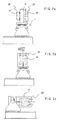
- FIGS. 2a-2c and FIGS. 3a-3c show an operation of the jig mounting device 1.
- FIG. 2a shows the state of the jig mounting device 1 with the jig 8 mounted thereon.
- FIG. 2b shows the state after the jig 8 is rotated by 90 in the direction of the arrow by rotary motion of the rotary member 6b in the state of FIG. 2a.
- FIG. 2c shows the state after the jig 8 is tilted 90 by a swing motion of the swing member 6a in the state of FIG. 2b.
- the jig mounting device 1 has been linearly moved from the position in FIG. 2b so that the positions of the workpieces 10 and 10' attached to the jig 8 are changed to the positions where a robot handles the workplaces 10 and 10'.
- FIG. 3a shows the state after the jig 8 is rotated by 90 in the direction of the arrow in the state of FIG. 2c.
- FIG. 3b shows th state after the jig 8 is tilted by 90 in the reverse direction in the state of FIG. 3a to stand up the main member 8a.
- FIG. 3c shows the state after the jig 8 is rotated by 90 in the state of FIG. 3b in the same direction of the arrow in FIG. 2b.
- the jig 8 can be held at a desired angular position by actuating the swing member 6a and the rotary member 6b by the servomotors.
- the orientation or posture of the workplaces 10 and 10' can be changed by the rotary and tilt motions of the jig 8 by the jig mounting unit 6.
- the orientation of the jig 8 is changed so that a hand 20a of a handling robot 20 can hold the workpiece 10 or 10' on the jig 8 with an orientation of a robot wrist where the minimum load is applied to the wrist axes when attaching and detaching the workpiece 10 on and from the jig 8, and also suitable for transferring and storing the workpiece into the storehouse.
- the orientation of the jig 8 in attaching/detaching of the workpiece 10 is selected to conform with the orientation of the workpiece 10 to be handled by the hand 20a of the handling robot 20.
- the workpiece 10 is held by the hand 20a with the orientation of the wrist directed downwardly at when the minimum load is applied to the wrist axes.
- the heavy workpiece 10 can be held and transported without exerting excessive moment on the axes of the wrist 20b, to release operators from the burden of changing the heavy workpiece.
- clamping work of a workpiece on the jig 8 can be performed by a robot using a clamping device 9b operated by means of screws.
- screws Conventionally, screws have to be rotationally driven from a back side of the jig for clamping the workpiece on the jig. This makes clamping work by a robot almost impossible.
- the jig mounting device 1 enables clamping of the workpiece on the jig by a robot, to realize automatic changing of the workpiece.
- pull bolts are fixedly screwed on the workpiece and the workpiece is clamped on the jig by pulling the pull bolts fixed on the workpiece towards the jig to enable the clamping operation by a robot.
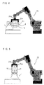
- FIG. 6 shows attaching and detaching operations of the pull bolts 11 on the workpiece 10 by a pull bolt attaching/detaching robot 30.
- Female screws for attaching the pull bolts are formed on the workpiece 10 in advance or in the first machining stage.
- a nut runner 40 for attaching/detaching the pull bolts is attached to a distal end of a wrist of the pull bolt attaching/detaching robot 30.
- the structure of the pull bolt 11 will be described referring to FIG. 6 and FIG. 7 showing attaching of the pull bolt to the workpiece 10.
- the pull bolt 11 has a male screw 11a for engagement with a female screw 10a formed on the workpiece 10.
- a flange 11b is formed at the proximal end of the male screw 11a for abutment with workpiece 10, and a small diameter portion is formed to continuously connect the flange 11b and a large diameter portion near the distal end of the pull bolt 11.
- the large diameter portion and the small diameter portion in combination form an engaging portion 11c having a curved surface for engaging with balls 53 of a ball lock mechanism 52 and pulling the pull bolt 11 towards the jig 8.
- a torque receiving portion 11d is formed to receive a screw driving torque.
- the torque receiving portion 11d is in the form of a hexagonal head.
- a pushing mechanism 40b is connected with an output shaft of a motor (servomotor) 40a as a driving source of the nut runner 40.
- the pushing mechanism 40b comprises a pipe connected with the output shaft of the motor and a spring disposed in the pipe.
- the outer periphery of the pipe at the distal end thereof is formed into a polygonal shape and slidably fitted into a polygonal hole formed at a proximal end of a transmission member 40c, so that rotational torque of the motor 40a is transmitted to the transmission member 40c. Further, the transmission member 40c is urged in the axial direction thereof by the spring inserted in the pipe.
- the transmission member 40c is rotated by the motor 40a and urged to move outwards by the pushing mechanism 40b.
- the transmission member 40c has a fitting portion 40d at a distal end thereof with a hole formed into a hexagonal shape to be fitted on the hexagonal torque receiving portion 11d of the pull bolt 11.
- Balls 40f are arranged circumferentially in an outer sleeve 40e and urged radially towards a central axis of the nut runner 40 by a ring like spring with a slit. The balls engages with the engaging portion 11c of the pull bolt 11 so as to securely hold the pull bolt 11 not to be dropped in changing of the orientation of the nut runner 40.
- the nut runner 40 held by the robot 30 is charged with a pull bolt 11 and the pull bolt 11 is pushed towards a threaded hole formed on the workpiece 10 by the robot.
- the fitting portion 40d of the transmitting member 40c is urged towards the torque receiving portion 11d of the pull bolt 11 by the spring in the pushing mechanism 40b.
- the transmitting member 40c is rotated by the motor 40a by a predetermined angle, e.g., one revolution, at a low speed.
- the fitting portion 40d rotates in contact with the torque receiving portion 11d of the pull bolt 11, the fitting portion 40d is fitted into and engaged with the torque receiving portion 11d.
- the pull bolt 11 rotates with the pushing mechanism 40b while being urged towards the workpiece 10 to start threaded engagement between the female screw formed on the workpiece 10 and the male screw 11a of the pull bolt 11. Subsequently, the pull bolt 11 is rotated at a high speed by the motor 40a and the male screw 11a is fitted in the female screw to make the flange 11a abut the surface of the workpiece 10 to increase the rotational torque of the motor 40a.
- the increase of the rotational torque (driving current) of the motor 40a is detected, the drive of the motor 40a is stopped and the nut runner 40 is moved to separate from the pull bolt 11 in the axial direction of the pull bolt 11 by the robot 30.
- the robot 30 In removing the pull bolt 11 from the workpiece 10, the robot 30 is positioned so that the axis of the nut runner 40 coincides with the axis the pull bolt 11 attached to the workpiece 10. Then, the nut runner 40 is moved towards the workpiece 10 along the axis of thereof, so that the pull bolt 11 is inserted into the outer sleeve 40e and the engaging portion 40d of the transmission member 40c abuts the torque receiving portion 11d and is urged towards the torque receiving portion 11d by the spring.
- the engaging portion 40d is rotated by a predetermined angle, e.g. one revolution, at a low speed so that the engaging portion 40d is fitted on the torque receiving portion 11d to transmit the rotation of the motor 40a to the pull bolt 11. Then, the motor 40a is driven at a high speed to remove the threaded engagement between the male screw and the female screw to remove the pull bolt 11 from the workpiece 10.
- FIG. 8 shows a state where the workpiece 10 with pull bolts 11 attached is mounted on the jig 8.
- the jig 8 has a pull bolt pulling mechanism for pulling the put bolt to fix and position the workpiece on the jig 8.
- the pull bolt pulling mechanism comprises a hydraulic cylinder device 50 and a ball lock mechanism 52 operatively connected to a piston of the hydraulic cylinder device 50.
- the ball lock mechanism 52 comprises a plurality of balls 53 arranged at the distal end of the piston of hydraulic cylinder device 50, and a fixed member 55 fixed to the jig 8 and having a tapered sleeve 54.
- the jig 8 has a hole 56 for insertion of the pull bolt 11 and fitting the flange 11b of the pull bolt 11 for positioning of the workplace 10 with respect to the jig 8.
- the hydraulic cylinder device 50 is arranged so that a central axis thereof coincides with the central axis of the hole 56.
- the piston 51 of the hydraulic cylinder device 50 is extended outside in the right-hand direction in FIG. 8 to allow the balls 53 to be positioned at a larger diameter portion on the tapered sleeve 54.
- the pull bolt 11 is inserted into the hole 56, so that the torque receiving portion 11d and a shoulder of the engaging portion 11c of the pull bolt 11 pass the ball 53 and are inserted into the hole of the piston 51.
- the hydraulic cylinder 50 is actuated to move the piston 51 remote from the pull bolt 11 in the left-hand direction indicated by the arrow in FIG.
- FIGS. 9-12 An operation for automatically changing a workpiece using the jig mounting device 1 will be described as a workpiece handling system for automation of transfer and changing of workpieces, as shown in FIGS. 9-12.
- the conventional clamping devices 9a for clamping a workpiece by hydraulically pressing the workpiece towards the jig 8 are employed for clamping a workpiece on the first attaching face F1 of the jig 8 for a first machining process
- the clamping devices 9b are employed using the pull bolts and the pull bolt pulling mechanism for clamping and positioning the workpiece on the second attaching face F2 of the jig 8 for a second machining.
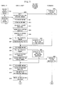
- FIGS. 11 and 12 show a flow diagram for an operation of the workpiece handling system including a controller for controlling the whole system, the handling robot for mounting/dismounting of the workpiece on the jig and transferring of the workpiece, the pull bolt attaching/detaching robot and the storehouse for store workpieces before machining and workpieces (products) after machining.
- FIGS. 9a-9b and FIGS. 10a-10b schematically show operation of the workpiece handling system.
- the pull bolt attaching/detaching robot 30 is disposed behind the jig mounting device 1.
- the controller issues an automatic operation start command to a controller of the handling robot 20 (S101).
- the controller of the handling robot 20 issues a command for bringing an empty a ready workpiece placing pallet to the storehouse 70 (S200).
- a ready workpiece placing pallet is brought to an entrance 71 of the storehouse 70 (S400).
- the jig mounting device 1 moves to a predetermined position under the lift 61 and then the lift 61 moves downward to place the jig 8 on the jig mounting device 1.
- the machine pallet 8b of the jig 8 is fixed by the fixing device 7.
- the jig mounting device 1 moves to a predetermined position for the operations by the handling robot 20 and the pull bolt attaching/detaching robot 30, and performs tilt/rotary motions after completing the second machining to achieve the orientation of the workpiece 10' suitable for detaching operation by the handling robot 20 (S201).
- the orientation of the workpiece 10' is set to an orientation in which the workpiece 10' is placed on the ready workpiece placing pallet for storage in the storehouse 70 and also in which the workpiece 10' can be held by the hand 20a of the handling robot 20.
- the second attachment face F2 of the jig 8 is set upside, as shown in FIG. 9a.
- a hand for holding a workpiece is attached to the wrist of the handling robot 20 (S202) and the workpiece 10' after finishing the second machining is held by the hand (S203).
- the hydraulic cylinder 50 of the jig 8 is actuated so that the piston is moved in the right-hand direction in FIG. 8 to release the clamping of the workpiece 10' on the jig 8 (S204).
- the handling robot 20 removes the held workpiece 10' from the jig 8 (S205) and issues a command for detaching--the pull bolts on the attachment face of the workpiece 10' to the pull bolt removing robot 30 (S206).
- the handling robot 20 moves the workpiece 10' to the position where the pull bolt attaching/detaching robot 30 can perform a detaching operation of the pull bolts from the workpiece 10' and hold the workpiece 10' at the position (S207).
- the pull bolt attaching/detaching robot 30 removes the pull bolts from the workpiece 10' by the nut runner 40, as described (S300).
- the jig mounting device 1 performs the tilting/rotary motion to make the orientation of the workpiece 10 attached to the first attachment face after finishing the first machining suitable for attaching operation of the pull bolts on the workpiece 10 by the pull bolt attaching/detaching robot 30 (S208) and issues a pull bolt attaching command to the pull bolt attaching/detaching robot 30 (S209).
- the pull bolt attaching/detaching robot 30 starts the attaching operation of the pull bolts on the workpiece 10 in response to the pull bolt attaching command (S301).
- This state of the jig mounting device 1 is shown in FIG. 6 where the pull bolts are attached to a first machining face of the workpiece 10 after finishing the first machining by the nut runner 40 of the robot 30.
- the handling robot 20 moves to the inlet/outlet place 71 of the storehouse 70 with the workpiece (product) 10' held by the hand and places the workpiece 10' on a product placing tray prepared at the inlet/outlet place 71 (S210) and issues a command for storing the product placing tray to the controller of the storehouse 70 (S211).
- the finished workpiece mounting tray is stored in the storehouse 70 in response to the command (S401).
- the jig mounting device 1 performs tilting/rotary motion to achieve the orientation of the workpiece 10 with the pull bolts attached suitable to be held by the handling robot 20 (S212).
- This state is shown in FIG. 5.
- the handling robot 20 is holding the workpiece 10 (S213) and the clamping of the workpiece 10 on the jig 8 by the clamping device 9a is released (S214).
- the handling robot 20 removes the workpiece 10 from the jig 8 (S215).
- FIG. 9b where the hand 20a of the handling robot 20 holds the workpiece 10 when removing the workpiece 10 from the first attachment face F1 of the jig 8.
- the jig mounting device 1 performs the tilting/rotary motion to make the orientation of the second attachment face F2 suitable for attaching the workpiece 10 with the pull bolt attached (S216). Then, the handling robot 20 attaches the workpiece 10 on the second attachment face F2. This state is shown in FIG. 10a.
- the pull bolts attached to the workpiece 10 are inserted into the holes 56 formed on the jig 8 and the workpiece 10 is positioned by the fitting of the holes 56 and the fitting flange 11b (S217).
- the hydraulic cylinders 50 are actuated to pull the pull bolts towards the jig 8 so that the workpiece 10 is fixed to the second machining face F2 of the jig 8 (S218).
- a command for bring a tray with an un-machined new workpiece is issued to the storehouse 70 (S219) and in response to the command a new workpiece on the tray is brought to the inlet/outlet port 71 of the storehouse 70 (S402).
- the jig mounting device 1 performs a tilting/rotary motion for making the orientation of the first attachment face F1 suitable for attachment of the new workpiece thereto (S220).
- the orientation of the first attachment face F1 is determined based on the orientation of the new workpiece with which the workpiece is held by the handling robot 20 when taken out from the storehouse 70 and the holding state of the new workpiece by the handling robot 20.
- the orientation of the first attachment face F1 is determined to be directed upward for easily mounting the new workpiece thereon, as shown in FIGS. 4 and 10b.
- the handling robot 20 holds up the new workpiece brought to the entrance 71 (S221) and issues a command for storing an empty tray to the storehouse 70 (S222). In response to the empty tray storing command, the storehouse 70 stores the empty tray therein (S403).
- the handling robot 20 transfers the new workpiece taken out from the storehouse 70 to the place for attachment of the new workpiece on the jig 8.
- the handling robot 20 then positions and attaches the new workpiece to the first attachment face F1 of the jig 8 (S223) and the new workpiece is clamped on the first attachment face F1 by the clamping device 9a (S224).
- the clamping of the workpiece on the first attachment face F1 is carried out by the conventional clamping device 9a for hydraulically pressing the workpiece on the jig 8. This state is shown in FIG. 10b where the new workpiece is to be mounted on the jig 8.
- the new workpiece is attached to the first attachment face F1 of the jig 8 and the workpiece 10 after the first machining is attached to the second attachment face F2.
- the jig mounting device 1 performs tilting/rotary action to give the jig the orientation as shown in FIG. 2a, and moves to the position under the lift 61 (S225).
- the hand is removed form the handling robot 20 (S226) and the handing robot 20 issues a program termination command to the controller of the system (S227).
- the controller of the system issues a display command for displaying a completion report of the automatic operation and a command for carrying a machine pallet (S102), and the jig 8 with the workplaces changed is transported by the carriage 60 (S103).
- the hand of the handling robot can hold the workpiece with an orientation of the robot wrist where the minimum load is applied to the wrist axes when attaching and detaching the workpiece on and from the jig, a heavy workpiece can be attached to and detached from the jig and also transferred by the handling robot, to thus reduce the work of operators.
- automatic changing of workplaces can be achieved.
- use of full bolts for fixing and positioning the workpiece on the jig enables a full automatic operation of attaching/detaching the workpiece to/from the jig to be achieved.
- the present invention provides a full automatic workpiece changing system in which a machined workpiece is automatically changed for a workpiece to be machined by employing the pull bolt attaching/detaching robot and the automatic storehouse.
Landscapes
- Engineering & Computer Science (AREA)
- Mechanical Engineering (AREA)
- Automatic Assembly (AREA)
- Manipulator (AREA)
- Feeding Of Workpieces (AREA)
Abstract
Description
Subsequently, the
Claims (6)
- A workpiece changing system for attaching a workpiece to be machined on a jig and/or detaching a machined workpiece from the jig by holding the workpiece with a robot hand attached to a handling robot, comprising:
a jig mounting device including a jig mounting unit on which the jig is mounted; fixing means for fixing the jig on said mounting unit; and orientation changing means for changing orientation of the jig on said jig mounting unit so that the orientation of the jig conforms to the orientation of the workpiece held or to be held by the robot hand in attaching/detaching of the workpiece to/from the jig. - A workpiece changing system according to claim 1, wherein said orientation changing means comprises rotating means for rotating said jig mounting unit and tilting means for tilting said jig mounting unit.
- A workpiece changing system according to claim 1 or 2, further comprising an automatic storehouse for storing workplaces to be machined and machined workpieces, wherein said handling robot handles a workpiece to be machined taken out from said storehouse to attach the workpiece to said jig mounted on said jig mounting device, and handles the machined workpiece to detach the machined workpiece from the jig mounted on said jig mounting device and transfer the machined workpiece to said automatic storehouse to be automatically stored therein.
- A workpiece changing system according to claim 1 or 2, further comprising: a pull bolt attaching/detaching robot having a pull bolt attaching/detaching device for attaching/detaching pull bolts to/from the workpiece by threaded engagement with threaded holes formed on the workpiece, the workpiece with the pull bolts attached being positioned on the jig by the handling robot,a pulling hydraulic cylinder device with a piston arranged at said jig; anda ball lock mechanism connected to the piston of said pulling hydraulic cylinder device for locking a distal end of the pull bolt, whereby the workpiece is fixed and positioned on the jig by a hydraulic pulling force of said piston.
- A workpiece changing system according to claim 4, wherein said pull bolt attaching/detaching device comprises a holding mechanism for holding a pull bolt, an engaging member to be engaged with the pull bolt held by said holding mechanism so as to transmit a rotational torque to the pull bolt, and a pushing mechanism for pushing said engaging member to be engaged with the pull bolt.
- A workpiece changing system according to claim 4 or 5, further comprising an automatic storehouse for storing workpieces to be machined and machined workpiece, wherein said handling robot handles a workpiece to be machined taken out from said storehouse to attach the workpiece to said jig mounted on said jig mounting device in cooperation with said pull bolt attaching/detaching robot, and handles the machined workpiece to detach the machined workpiece from the jig mounted on said jig mounting device and transfer the machined workpiece to said automatic storehouse to be automatically stored therein.
Applications Claiming Priority (2)
| Application Number | Priority Date | Filing Date | Title |
|---|---|---|---|
| JP2000189575 | 2000-06-23 | ||
| JP2000189575A JP3586623B2 (en) | 2000-06-23 | 2000-06-23 | Work exchange device and work handling system |
Publications (3)
| Publication Number | Publication Date |
|---|---|
| EP1166955A2 true EP1166955A2 (en) | 2002-01-02 |
| EP1166955A3 EP1166955A3 (en) | 2002-10-09 |
| EP1166955B1 EP1166955B1 (en) | 2008-08-20 |
Family
ID=18689187
Family Applications (1)
| Application Number | Title | Priority Date | Filing Date |
|---|---|---|---|
| EP01305501A Expired - Lifetime EP1166955B1 (en) | 2000-06-23 | 2001-06-25 | System for attaching / detaching a workpiece to be machined on a jig |
Country Status (4)
| Country | Link |
|---|---|
| US (1) | US6772493B2 (en) |
| EP (1) | EP1166955B1 (en) |
| JP (1) | JP3586623B2 (en) |
| DE (1) | DE60135413D1 (en) |
Cited By (5)
| Publication number | Priority date | Publication date | Assignee | Title |
|---|---|---|---|---|
| EP1449649A3 (en) * | 2003-02-24 | 2008-03-26 | Think Laboratory Co., Ltd. | Turn-table type cylinder stock in a plating factory for gravure printing cylinders |
| CN104308740A (en) * | 2014-11-07 | 2015-01-28 | 南京市锅炉压力容器检验研究院 | Grinding deviation preventing device for automatically grinding active safety valve seat by driving grinding head with motor |
| CN104526714A (en) * | 2014-12-01 | 2015-04-22 | 岑溪市东正动力科技开发有限公司 | Hydraulic mechanical arm capable of realizing wide-angle turning |
| US10549466B2 (en) | 2015-10-23 | 2020-02-04 | Fanuc Corporation | Injection molding system |
| CN110961944A (en) * | 2019-12-19 | 2020-04-07 | 马鞍山市兴隆铸造有限公司 | Fixing mechanism for casting mold machining |
Families Citing this family (32)
| Publication number | Priority date | Publication date | Assignee | Title |
|---|---|---|---|---|
| DE10144248A1 (en) * | 2001-08-31 | 2003-03-27 | Felsomat Gmbh & Co Kg | handling device |
| JP4025069B2 (en) * | 2001-12-28 | 2007-12-19 | 大日本スクリーン製造株式会社 | Substrate processing apparatus and substrate processing method |
| JP3865703B2 (en) * | 2002-10-25 | 2007-01-10 | ファナック株式会社 | Article conveying system and conveying method |
| JP3830477B2 (en) * | 2003-09-04 | 2006-10-04 | ファナック株式会社 | Work transfer device |
| JP2006043866A (en) * | 2004-06-30 | 2006-02-16 | Fanuc Ltd | Machine tool having pallet exchange function and pallet exchange method |
| KR100667380B1 (en) * | 2005-11-02 | 2007-01-10 | 현대자동차주식회사 | Flow passage closure device of engine |
| US7322083B2 (en) * | 2005-11-30 | 2008-01-29 | Nokia Corporation | Manufacturing system architecture for tools |
| US7346426B2 (en) * | 2006-03-06 | 2008-03-18 | Fu-Zhun Precision Industry (Shen Zhen) Co., Ltd. | Automatic dotting machine for manufacture of heat sink for electronic component |
| JP2008149328A (en) * | 2006-12-14 | 2008-07-03 | Shiga Yamashita:Kk | Casting finishing equipment |
| US8025277B2 (en) * | 2008-02-06 | 2011-09-27 | GM Global Technology Operations LLC | Reconfigurable end-of-arm tool for robotic arm |
| WO2009113360A1 (en) * | 2008-03-10 | 2009-09-17 | 本田技研工業株式会社 | Door removing system and door removing method |
| NL2002040C (en) * | 2008-09-30 | 2010-03-31 | Pex Rent B V | COMPOSITION AND METHOD FOR MILLING AN OBJECT WITH A MILLING MACHINE |
| CN103072068A (en) * | 2011-10-26 | 2013-05-01 | 北京实验工厂 | Positioning fixture for high-precision honing of inner hole of valve pocket |
| CN203237742U (en) * | 2012-11-28 | 2013-10-16 | 富鼎电子科技(嘉善)有限公司 | Turnover machine |
| CN103433922B (en) * | 2013-09-06 | 2015-06-17 | 哈尔滨工业大学 | Three-degree-of-freedom telecentric concurrent type heavy-load posture adjustment mechanism |
| JP6366932B2 (en) * | 2013-12-10 | 2018-08-01 | 川崎重工業株式会社 | Work reversal support device and robot cell equipped with the same |
| EP3107685A1 (en) * | 2014-02-21 | 2016-12-28 | SK-Technologies UG | Robot cell for the loading and unloading of single-station machine tools during machining |
| JP2016203280A (en) * | 2015-04-17 | 2016-12-08 | セイコーエプソン株式会社 | Robot and control device |
| JP2017035757A (en) * | 2015-08-11 | 2017-02-16 | ファナック株式会社 | Machining system including a machine tool and a robot for attaching and detaching a workpiece |
| IT201600092105A1 (en) * | 2016-09-13 | 2018-03-13 | Adige Spa | Support device for supporting a tube on a tube processing machine, particularly a machine for laser cutting of tubes, and a machine for processing tubes comprising such a support device. |
| JP6606667B2 (en) | 2016-09-30 | 2019-11-20 | パナソニックIpマネジメント株式会社 | Component mounting equipment |
| CN106313032B (en) * | 2016-10-18 | 2018-11-16 | 盛亚明 | A kind of new-energy automobile lithium battery electric core annular grabbing device |
| CN109789548B (en) * | 2016-11-08 | 2022-06-28 | Abb瑞士股份有限公司 | Method for workpiece calibration and robot system using the same |
| US10661401B2 (en) * | 2017-02-24 | 2020-05-26 | Panasonic Intellectual Property Management Co., Ltd. | Component mounted body manufacturing system and component mounted body manufacturing method |
| KR102075933B1 (en) * | 2017-10-30 | 2020-05-19 | 한국생산기술연구원 | Robot system for controlling load of machine depending on tool wear and method for controlling load of machine using the same |
| JP7044326B2 (en) * | 2018-04-11 | 2022-03-30 | 国立大学法人千葉大学 | Multi-axis robot fixing device and processing system |
| CN108500379B (en) * | 2018-05-02 | 2024-03-19 | 宁波敏实汽车零部件技术研发有限公司 | Automatic quick-change equipment for saw blade in automobile part production |
| CN108972039A (en) * | 2018-08-15 | 2018-12-11 | 芜湖源码自动化设备有限公司 | It is a kind of to facilitate fixed multi-angle frock clamp |
| EP3769912A1 (en) * | 2019-07-23 | 2021-01-27 | Erst-Maschinenbau GmbH | Machine tool cocoon, tool changing device and machine tool |
| JP7363755B2 (en) * | 2020-12-15 | 2023-10-18 | 株式会社ダイフク | Screw member tightening/loosening device and screw member tightening/loosening method |
| JP7628295B2 (en) * | 2021-09-01 | 2025-02-10 | 国立研究開発法人量子科学技術研究開発機構 | Gripping system, Gripping method, Gripping device |
| CN116423275B (en) * | 2023-04-24 | 2023-11-14 | 盐城支点机械制造有限公司 | Feeding and discharging equipment for machining oil pump shell |
Family Cites Families (40)
| Publication number | Priority date | Publication date | Assignee | Title |
|---|---|---|---|---|
| GB851608A (en) * | 1956-12-21 | 1960-10-19 | Nils Johannes Liaaen | Servomotor control system |
| US3657963A (en) * | 1970-01-12 | 1972-04-25 | Richard K Miller | Rotary tilting table |
| NO138196C (en) * | 1971-06-14 | 1978-07-26 | Avondale Shipyards Inc | FACILITY FOR HOLDING A WORKPIECE |
| US5608847A (en) * | 1981-05-11 | 1997-03-04 | Sensor Adaptive Machines, Inc. | Vision target based assembly |
| JPS58191932A (en) | 1982-05-07 | 1983-11-09 | Tsuneya Tsubokawa | Absolute measuring method of gravity |
| US4809425A (en) * | 1984-02-06 | 1989-03-07 | Monforte Robotics, Inc. | Adaptable, programmable production system |
| JPS6138844A (en) * | 1984-07-31 | 1986-02-24 | Tsubakimoto Chain Co | Work passing device for robot |
| CH661237A5 (en) * | 1984-12-19 | 1987-07-15 | Arcofil Sa | METHOD FOR AUTOMATICALLY LOADING WORKSTATIONS AND DEVICE FOR CARRYING OUT SAID METHOD. |
| US4685661A (en) * | 1985-06-21 | 1987-08-11 | The United States Of America As Represented By The Secretary Of Commerce | Method and mechanism for fixturing objects |
| US4667805A (en) * | 1985-11-06 | 1987-05-26 | Westinghouse Electric Corp. | Robotic part presentation system |
| DE3541638A1 (en) * | 1985-11-26 | 1986-04-30 | Josip 6954 Haßmersheim Siniko | WORKPIECE HOLDING DEVICE |
| JPS62259749A (en) * | 1986-04-11 | 1987-11-12 | Kotobuki:Kk | Machining method using industrial robot |
| US5219264A (en) * | 1986-09-19 | 1993-06-15 | Texas Instruments Incorporated | Mobile robot on-board vision system |
| JPS63225024A (en) * | 1987-03-11 | 1988-09-20 | Honda Motor Co Ltd | Transfer equipment |
| JPS6456938A (en) | 1987-04-17 | 1989-03-03 | Fuji Heavy Ind Ltd | Air-fuel ratio controller for engine |
| US4988261A (en) * | 1989-10-06 | 1991-01-29 | Blatt John A | Multiple motion transfer apparatus |
| JPH03202248A (en) * | 1989-12-28 | 1991-09-04 | Mitsubishi Heavy Ind Ltd | Automatic workpiece changer for machine tool |
| CA2012117C (en) * | 1990-02-12 | 2001-05-01 | John Ingvar Emanuel Johansson | A manipulator intended for cooperation with an industrial robot |
| JPH04100689A (en) * | 1990-08-14 | 1992-04-02 | Tsubakimoto Chain Co | 5-axis table for laser processing machine |
| DE4027895A1 (en) * | 1990-09-03 | 1992-03-05 | Wanderer Maschinen Gmbh | Workpiece table for machine tool - can be rotated about axis which is at right angles to spindle axis |
| JPH04183581A (en) * | 1990-11-15 | 1992-06-30 | Fanuc Ltd | Robot for loading and unloading work onto machine tool |
| US5293179A (en) * | 1990-11-20 | 1994-03-08 | Canon Kabushiki Kaisha | Work convey method and apparatus |
| JPH05131335A (en) | 1991-02-26 | 1993-05-28 | Fujitsu Kiden Ltd | Angle changing mechanism |
| JP3273619B2 (en) | 1991-08-22 | 2002-04-08 | オリンパス光学工業株式会社 | Electronic imaging device |
| JPH05104366A (en) * | 1991-10-17 | 1993-04-27 | Fanuc Ltd | Combined machine tool |
| JPH05245728A (en) * | 1992-03-03 | 1993-09-24 | Mitsubishi Materials Corp | Bolt attachment / detachment device |
| JPH06190651A (en) * | 1992-12-26 | 1994-07-12 | Nippon Densan Corp | Robot |
| US5509777A (en) * | 1993-03-25 | 1996-04-23 | Leland D. Blatt | Mechanical side shift and tip apparatus |
| US5365810A (en) * | 1993-07-30 | 1994-11-22 | Hitachi Koki Co., Ltd. | Screw supply control apparatus for screw tightening robot |
| JPH0760591A (en) | 1993-08-25 | 1995-03-07 | Honda Motor Co Ltd | Work transfer loader |
| US5471738A (en) * | 1993-10-04 | 1995-12-05 | Ford Motor Company | Robotic system for inserting cylinder liners into internal combustion engine cylinder blocks |
| JPH07155871A (en) * | 1993-12-06 | 1995-06-20 | Komatsu Ltd | Robot work replacement control device and work replacement device |
| JP3012463B2 (en) * | 1993-12-22 | 2000-02-21 | 松下電工株式会社 | Assembly equipment |
| US5588794A (en) * | 1994-07-18 | 1996-12-31 | Ford Motor Company | Robotic gripper |
| JP3074444B2 (en) * | 1994-12-13 | 2000-08-07 | 本田技研工業株式会社 | Work transfer device |
| JP3433552B2 (en) * | 1995-02-03 | 2003-08-04 | マツダ株式会社 | Parts assembly equipment |
| JPH08243873A (en) | 1995-03-06 | 1996-09-24 | Miyano:Kk | Method for switching work transfer direction of work gripping tool, and loading / unloading device |
| JP3569069B2 (en) * | 1996-04-23 | 2004-09-22 | 株式会社コスメック | Clamping device |
| KR100251560B1 (en) | 1996-10-29 | 2000-04-15 | 윤종용 | Apparatus for rejecting the outer interference signal in cdma terminal equipmeut |
| JP2001101958A (en) * | 1999-09-30 | 2001-04-13 | Oki Electric Ind Co Ltd | Tool for retracting insert/pull pawl for pin insert/pull robot |
-
2000
- 2000-06-23 JP JP2000189575A patent/JP3586623B2/en not_active Expired - Fee Related
-
2001
- 2001-06-22 US US09/885,924 patent/US6772493B2/en not_active Expired - Lifetime
- 2001-06-25 EP EP01305501A patent/EP1166955B1/en not_active Expired - Lifetime
- 2001-06-25 DE DE60135413T patent/DE60135413D1/en not_active Expired - Lifetime
Cited By (5)
| Publication number | Priority date | Publication date | Assignee | Title |
|---|---|---|---|---|
| EP1449649A3 (en) * | 2003-02-24 | 2008-03-26 | Think Laboratory Co., Ltd. | Turn-table type cylinder stock in a plating factory for gravure printing cylinders |
| CN104308740A (en) * | 2014-11-07 | 2015-01-28 | 南京市锅炉压力容器检验研究院 | Grinding deviation preventing device for automatically grinding active safety valve seat by driving grinding head with motor |
| CN104526714A (en) * | 2014-12-01 | 2015-04-22 | 岑溪市东正动力科技开发有限公司 | Hydraulic mechanical arm capable of realizing wide-angle turning |
| US10549466B2 (en) | 2015-10-23 | 2020-02-04 | Fanuc Corporation | Injection molding system |
| CN110961944A (en) * | 2019-12-19 | 2020-04-07 | 马鞍山市兴隆铸造有限公司 | Fixing mechanism for casting mold machining |
Also Published As
| Publication number | Publication date |
|---|---|
| EP1166955B1 (en) | 2008-08-20 |
| JP2002011635A (en) | 2002-01-15 |
| JP3586623B2 (en) | 2004-11-10 |
| US6772493B2 (en) | 2004-08-10 |
| DE60135413D1 (en) | 2008-10-02 |
| EP1166955A3 (en) | 2002-10-09 |
| US20010054223A1 (en) | 2001-12-27 |
Similar Documents
| Publication | Publication Date | Title |
|---|---|---|
| EP1166955B1 (en) | System for attaching / detaching a workpiece to be machined on a jig | |
| EP3003647B1 (en) | Crimping head for impact wrench | |
| CA2501004A1 (en) | Pieces hold-unit for workstations, transfer machines and like | |
| US6113087A (en) | Work holding apparatus | |
| CN112846900A (en) | Automatic unloader that goes up in vertical machining center side | |
| CN210649840U (en) | Feeding and discharging device for drill bit grinding equipment | |
| JP7676438B2 (en) | Gripping tool, system and clamping tool, exchange station and method for handling objects using said system or clamping tool - Patents.com | |
| US4550922A (en) | Workholder | |
| JPS63312049A (en) | Machine tool | |
| EP0705157B1 (en) | Automatic tool change | |
| CN218426763U (en) | Efficient assembling equipment capable of clamping in two directions for machining gaskets | |
| JP3871665B2 (en) | Workpiece handling method | |
| CN112571436A (en) | A supplementary clamping device for processing irregular pipeline outer wall | |
| JP2004237444A (en) | Work change device and work handling system | |
| CN116833785A (en) | A gear positioning drilling fixture | |
| CN120941070B (en) | Intelligent workstation for rocket large shell section instrument installation | |
| CN219005390U (en) | Automatic mechanical clamp for numerical control machine tool machining | |
| CN219725918U (en) | Rotatable clamp for processing elevator spare and accessory parts | |
| CN218659130U (en) | General tongs of arm | |
| JPH07266156A (en) | Bolt fastening jig and bolt | |
| CN218518572U (en) | Light-weight sleeve type positioning pin dismounting device | |
| CN209632510U (en) | Self-regulated arm automatic processing device | |
| CN2584326Y (en) | Improved drill chuck backcover and closefisted drill chuck with the backcover | |
| EP0218756A1 (en) | Improved workholder | |
| CN121756131A (en) | Auxiliary tool changing device and method for machining narrow groove with large depth |
Legal Events
| Date | Code | Title | Description |
|---|---|---|---|
| PUAI | Public reference made under article 153(3) epc to a published international application that has entered the european phase |
Free format text: ORIGINAL CODE: 0009012 |
|
| AK | Designated contracting states |
Kind code of ref document: A2 Designated state(s): AT BE CH CY DE DK ES FI FR GB GR IE IT LI LU MC NL PT SE TR |
|
| AX | Request for extension of the european patent |
Free format text: AL;LT;LV;MK;RO;SI |
|
| PUAL | Search report despatched |
Free format text: ORIGINAL CODE: 0009013 |
|
| AK | Designated contracting states |
Kind code of ref document: A3 Designated state(s): AT BE CH CY DE DK ES FI FR GB GR IE IT LI LU MC NL PT SE TR |
|
| AX | Request for extension of the european patent |
Free format text: AL;LT;LV;MK;RO;SI |
|
| 17P | Request for examination filed |
Effective date: 20030401 |
|
| AKX | Designation fees paid |
Designated state(s): DE |
|
| RAP1 | Party data changed (applicant data changed or rights of an application transferred) |
Owner name: FANUC LTD |
|
| GRAC | Information related to communication of intention to grant a patent modified |
Free format text: ORIGINAL CODE: EPIDOSCIGR1 |
|
| GRAP | Despatch of communication of intention to grant a patent |
Free format text: ORIGINAL CODE: EPIDOSNIGR1 |
|
| GRAS | Grant fee paid |
Free format text: ORIGINAL CODE: EPIDOSNIGR3 |
|
| GRAA | (expected) grant |
Free format text: ORIGINAL CODE: 0009210 |
|
| AK | Designated contracting states |
Kind code of ref document: B1 Designated state(s): DE |
|
| REF | Corresponds to: |
Ref document number: 60135413 Country of ref document: DE Date of ref document: 20081002 Kind code of ref document: P |
|
| PLBE | No opposition filed within time limit |
Free format text: ORIGINAL CODE: 0009261 |
|
| STAA | Information on the status of an ep patent application or granted ep patent |
Free format text: STATUS: NO OPPOSITION FILED WITHIN TIME LIMIT |
|
| 26N | No opposition filed |
Effective date: 20090525 |
|
| REG | Reference to a national code |
Ref country code: DE Ref legal event code: R082 Ref document number: 60135413 Country of ref document: DE Representative=s name: HASELTINE LAKE LLP, DE |
|
| PGFP | Annual fee paid to national office [announced via postgrant information from national office to epo] |
Ref country code: DE Payment date: 20200609 Year of fee payment: 20 |
|
| REG | Reference to a national code |
Ref country code: DE Ref legal event code: R082 Ref document number: 60135413 Country of ref document: DE Representative=s name: HL KEMPNER PATENTANWALT, RECHTSANWALT, SOLICIT, DE |
|
| REG | Reference to a national code |
Ref country code: DE Ref legal event code: R071 Ref document number: 60135413 Country of ref document: DE |