EP1166900A2 - Multiple contents container assembly for ultrapure solvent purging - Google Patents
Multiple contents container assembly for ultrapure solvent purging Download PDFInfo
- Publication number
- EP1166900A2 EP1166900A2 EP01114678A EP01114678A EP1166900A2 EP 1166900 A2 EP1166900 A2 EP 1166900A2 EP 01114678 A EP01114678 A EP 01114678A EP 01114678 A EP01114678 A EP 01114678A EP 1166900 A2 EP1166900 A2 EP 1166900A2
- Authority
- EP
- European Patent Office
- Prior art keywords
- solvent
- source chemical
- ampoule
- assembly
- high purity
- Prior art date
- Legal status (The legal status is an assumption and is not a legal conclusion. Google has not performed a legal analysis and makes no representation as to the accuracy of the status listed.)
- Granted
Links
Images



Classifications
-
- B—PERFORMING OPERATIONS; TRANSPORTING
- B08—CLEANING
- B08B—CLEANING IN GENERAL; PREVENTION OF FOULING IN GENERAL
- B08B9/00—Cleaning hollow articles by methods or apparatus specially adapted thereto
- B08B9/08—Cleaning containers, e.g. tanks
- B08B9/20—Cleaning containers, e.g. tanks by using apparatus into or on to which containers, e.g. bottles, jars, cans are brought
- B08B9/28—Cleaning containers, e.g. tanks by using apparatus into or on to which containers, e.g. bottles, jars, cans are brought the apparatus cleaning by splash, spray, or jet application, with or without soaking
- B08B9/34—Arrangements of conduits or nozzles
-
- B—PERFORMING OPERATIONS; TRANSPORTING
- B08—CLEANING
- B08B—CLEANING IN GENERAL; PREVENTION OF FOULING IN GENERAL
- B08B9/00—Cleaning hollow articles by methods or apparatus specially adapted thereto
- B08B9/02—Cleaning pipes or tubes or systems of pipes or tubes
- B08B9/027—Cleaning the internal surfaces; Removal of blockages
- B08B9/032—Cleaning the internal surfaces; Removal of blockages by the mechanical action of a moving fluid, e.g. by flushing
-
- B—PERFORMING OPERATIONS; TRANSPORTING
- B08—CLEANING
- B08B—CLEANING IN GENERAL; PREVENTION OF FOULING IN GENERAL
- B08B9/00—Cleaning hollow articles by methods or apparatus specially adapted thereto
-
- C—CHEMISTRY; METALLURGY
- C23—COATING METALLIC MATERIAL; COATING MATERIAL WITH METALLIC MATERIAL; CHEMICAL SURFACE TREATMENT; DIFFUSION TREATMENT OF METALLIC MATERIAL; COATING BY VACUUM EVAPORATION, BY SPUTTERING, BY ION IMPLANTATION OR BY CHEMICAL VAPOUR DEPOSITION, IN GENERAL; INHIBITING CORROSION OF METALLIC MATERIAL OR INCRUSTATION IN GENERAL
- C23C—COATING METALLIC MATERIAL; COATING MATERIAL WITH METALLIC MATERIAL; SURFACE TREATMENT OF METALLIC MATERIAL BY DIFFUSION INTO THE SURFACE, BY CHEMICAL CONVERSION OR SUBSTITUTION; COATING BY VACUUM EVAPORATION, BY SPUTTERING, BY ION IMPLANTATION OR BY CHEMICAL VAPOUR DEPOSITION, IN GENERAL
- C23C16/00—Chemical coating by decomposition of gaseous compounds, without leaving reaction products of surface material in the coating, i.e. chemical vapour deposition [CVD] processes
- C23C16/44—Chemical coating by decomposition of gaseous compounds, without leaving reaction products of surface material in the coating, i.e. chemical vapour deposition [CVD] processes characterised by the method of coating
- C23C16/4401—Means for minimising impurities, e.g. dust, moisture or residual gas, in the reaction chamber
- C23C16/4407—Cleaning of reactor or reactor parts by using wet or mechanical methods
-
- Y—GENERAL TAGGING OF NEW TECHNOLOGICAL DEVELOPMENTS; GENERAL TAGGING OF CROSS-SECTIONAL TECHNOLOGIES SPANNING OVER SEVERAL SECTIONS OF THE IPC; TECHNICAL SUBJECTS COVERED BY FORMER USPC CROSS-REFERENCE ART COLLECTIONS [XRACs] AND DIGESTS
- Y10—TECHNICAL SUBJECTS COVERED BY FORMER USPC
- Y10T—TECHNICAL SUBJECTS COVERED BY FORMER US CLASSIFICATION
- Y10T137/00—Fluid handling
- Y10T137/2931—Diverse fluid containing pressure systems
- Y10T137/3115—Gas pressure storage over or displacement of liquid
- Y10T137/3127—With gas maintenance or application
-
- Y—GENERAL TAGGING OF NEW TECHNOLOGICAL DEVELOPMENTS; GENERAL TAGGING OF CROSS-SECTIONAL TECHNOLOGIES SPANNING OVER SEVERAL SECTIONS OF THE IPC; TECHNICAL SUBJECTS COVERED BY FORMER USPC CROSS-REFERENCE ART COLLECTIONS [XRACs] AND DIGESTS
- Y10—TECHNICAL SUBJECTS COVERED BY FORMER USPC
- Y10T—TECHNICAL SUBJECTS COVERED BY FORMER US CLASSIFICATION
- Y10T137/00—Fluid handling
- Y10T137/4238—With cleaner, lubrication added to fluid or liquid sealing at valve interface
- Y10T137/4245—Cleaning or steam sterilizing
- Y10T137/4259—With separate material addition
-
- Y—GENERAL TAGGING OF NEW TECHNOLOGICAL DEVELOPMENTS; GENERAL TAGGING OF CROSS-SECTIONAL TECHNOLOGIES SPANNING OVER SEVERAL SECTIONS OF THE IPC; TECHNICAL SUBJECTS COVERED BY FORMER USPC CROSS-REFERENCE ART COLLECTIONS [XRACs] AND DIGESTS
- Y10—TECHNICAL SUBJECTS COVERED BY FORMER USPC
- Y10T—TECHNICAL SUBJECTS COVERED BY FORMER US CLASSIFICATION
- Y10T137/00—Fluid handling
- Y10T137/8593—Systems
- Y10T137/86348—Tank with internally extending flow guide, pipe or conduit
Definitions
- the Present Invention is directed to the field of process chemical delivery in the electronics industry and other applications requiring high purity chemical delivery. More specifically, the present invention is directed to apparatus and processes for the cleaning of process chemical delivery lines, containers and associated apparatus, particularly during changeout of process chemical or process chemical containers in such process chemical delivery lines.
- Evacuation and gas purge of process chemical lines has been used to remove residual chemicals from delivery lines. Both vacuum draw and inert gas purge are successful in quickly removing high volatility chemicals, but are not effective with low volatility chemicals. Safety is a problem when extracting highly toxic materials.
- solvent cleaning include; US4,357,175, US4,832,753, US4,865,061, US4,871,416, US5,051,135, US5,106,404, US5,108,582, US5,240,507, US5,304,253, US5,339,844, US5,425,183, US5,469,876, US5,509,431, US5,538,025, US5,562,883 and Japanese 8-115886.
- the Present Invention is a process and apparatus to deliver both process chemical and solvent for cleaning the process chemical in a solvent purge refill system along with an integral solvent capture ampoule, in a single "assembly" that permits ease of shipping, minimal end-user interaction, sufficient solvent for the solvent purge operation, without residual solvent, requiring disposal.
- This eliminates customer handling of the solvent, and eliminates the customer's need to find a solvent waste facility, as residual solvent can be returned in the same package in one piece/one step.
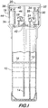
- FIG 1 is a schematic cross-sectional illustration of a first embodiment of the Present Invention.
- FIG 2 is a schematic cross-sectional illustration of an embodiment of the Present Invention.
- FIG 3 is a schematic partial cross-sectional illustration of an embodiment of the Present Invention.
- FIG 4 is a schematic cross-sectional illustration of an embodiment of the Present Invention.
- FIG 5 is a perspective view of one of two mirror image mating bracket sections for holding the solvent ampoules on a source chemical container.
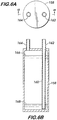
- FIG 6 A and B are a plan view and a cross-sectional view of an embodiment of a solvent ampoule of the Present Invention.
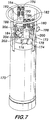
- FIG 7 is a perspective view of a source chemical container, solvent support bracket, solvent ampoule and solvent capture ampoule of a preferred embodiment of the Present Invention.
- FIG 8 is a schematic illustration of a manifold for an embodiment of the Present Invention.
- the Present Invention comprises a plurality of vessels, minimally two vessels; typically, but not exclusively, made from stainless steel, or other suitable materials that are not reactive with the process chemical or solvents in question.
- the materials of construction of these containers can include, but is not limited to: various types of steel, 316 stainless steel, nickel, Hasteloy, aluminum, chromium or other metals; various types of plastics and polymers, including Teflon, polypropylene, polyethylene, and similar compounds; ceramic materials, including silicon carbide, alumina, and similar compunds; and glass containers, including borosilicate glass, fused quartz and similar compounds.
- Either or both of the source chemical and solvent vessels may include liners, internal plating, and other materials of construction.
- the solvent and source chemical container vessels are not required to be manufactured from the same material, such that the source chemical container may be constructed from steel, while a solvent ampoule may be constructed from plastic, for example.
- the solvent container may contain a plurality of chambers, fluidly communicating with a single outlet or a plurality of outlets, such that the solvent provided for solvent cleaning may be available for more than one cycle, and may be used for alternate chemistries, for example, one chamber may contain a washing ingredient, while another chamber may contain a rinsing ingredient.
- one or more chambers may contain a solvent sorption media, wherein one application is to convert a volatile organic chemical (VOC) residue into a solid waste for more convenient handling.
- VOC volatile organic chemical
- the main source chemical container comprises a large (from 1 liter to 200 or more liter) container, which comprises a sealed storage volume typically filled with process chemicals, a metallic or non-metallic diptube attached either permanently (welded) or removeably (bolted on) extending to near the bottom of the source chemical container, an internal or external level sense, with at least one of the level sensors placed in such a position, typically just above the bottom of the dip tube, that it can indicate low level in the source chemical container.
- This level sensor may comprise any of the following: metallic or non-metallic float sensors; discrete or continuous ultrasonic level sensors; continuous or discrete thermal sensors; capacitive and or conductivity based level sensors; RF based level sensors; and other similar internal level sensors; or external sensors such as scales, load cells, external ultrasonic or thermal sensors placed either on the container or around the chemical delivery lines; and other similar means for detecting low level.
- the low level detection is routed to a solvent purge controller and/or to an operator in order to signal that a solvent purge process is required.
- the source chemical container will also comprise a plurality of valves, with a minimum of at least one outlet valve attached to the diptube, and in most cases will include a second valve for inert push gas, and/or a third valve for transfer of process chemical from an independent source of process chemical.
- Each of these valves can be connected integrally either permanently (welded on) or removably (bolted on, through a VCR connection for example).
- the valves may be manual, but preferably are automatic, comprising pneumatic, electric, hydraulic or solenoid actuated valves.
- the source chemical container also comprises a chime ring that is placed on support structures and is used to protect the process valves during shipment.
- source chemical container may integrally contain one or more smaller or secondary "solvent” ampoules either mounted entirely within or otherwise integral to the source chemical container, as opposed to a separate ampoule welded on or bolted on to the source chemical container.
- the secondary "solvent" ampoule comprises a small (50 milliliter to one liter) container, which comprises a sealed storage volume typically filled with a solvent that is selected by nature of it's solubility for the process chemical, a metallic or non-metallic diptube either permanently (welded) or removably (bolted on) extending to near the bottom of the solvent ampoule.
- An external or internal level sensor may optionally be used in this application also, although with less of a requirement than is needed with the source chemical container. The purpose of this level sensor would be to indicate that the solvent ampoule is empty and to cease further attempts at solvent washing.
- This level sensor may comprise any of the following: metallic or non-metallic float sensors; discrete or continuous ultrasonic level sensors; continuous or discrete thermal sensors; capacitive and or conductivity based level sensors; RF based level sensors; and other similar internal level sensors; or external sensors such as scales, load cells, external ultrasonic or thermal sensors placed either on the ampoule or around the chemical delivery lines; and other similar means for detecting low level.
- the solvent ampoule also includes two openings in the ampoule, one connected to the diptube, and extending to the bottom of the ampoule such that all solvent may be used in the solvent purge process.
- the other opening extends only into the headspace of the solvent ampoule, and is used for alternately pressurizing, venting and depressurizing the solvent container during the solvent purge operation.
- These openings may be sealed with manual or pneumatically actuated valves, and attached to the solvent purge control manifold with standard VCR-type or other high purity connectors.
- the openings may also be sealed with automatically sealing quick disconnect fittings.
- the fittings on the solvent ampoule are keyed to prevent accidental crossing of the inlet (headspace) and outlet (diptube) volumes in the solvent ampoule.
- This solvent ampoule may comprise a plurality of chambers separated by either vertical (longitudinal) or horizontal (lateral) barriers, which can be used to isolate various cleaning solvents reactive materials or rinse materials, and/or additional solvent for multiple cleaning operations, or for use as a solvent recovery ampoule, either by pushing the solvent into the chamber as a fluid, or by absorbing the solvent into a solid media, such as carbon, and any number of alternative solvent absorbing media, of which a number are available on the open market.
- This chamber or preferably ampoule is located such that solvent vapors or liquid can be drawn into it, either by process vacuum or through push gas pressure (fluidly communicating with the solvent ampoule), such elevated pressure potentially provided upon initial filling of the solvent ampoule.
- the sorbent media placed in the solvent capture ampoule can be a number of types of material suitable for trapping and holding the cleaning solvent.
- activated carbon may be used to capture volatile organic compounds, while materials such as acrylic polymers and caustic and/or acid neutralizers may be used depending on the solvent types.
- the sorbent material may also comprise liquids that can be used to improve the hazard ratings of the used solvent.
- Such sorbent materials can be perfluorocarbons, chlorofluorocarbons, and hydrocarbons of either high volatility (such as the perfluorocarbons) or low volatility (such as oils, i.e., Fomblin type fluorocarbon vacuum pump oil), and similar inert compounds. Both low volatility and high volatility in inert sorbent materials may be used depending on process requirements.
- each chamber will have at least one, and in most cases a plurality of ports for the delivery of the solvent to the process, and to provide inert gas pressure for pushing the solvent out of the ampoules.
- at least one, but in most cases a plurality of valves are used to direct the spent solvent into the ampoule and to provide a venting or vacuuming of the ampoule to accelerate the absorption of the solvent onto the media.
- the source of the pressure for the solvent ampoule may come from a pre-pressurization prior to delivery of the solvent ampoule, thereby precluding the need for an inert gas source on the solvent ampoule inlet, and even minimizing the need for such an inlet.
- the capture ampoule may be provided under pre-established vacuum so that spent solvent material may be directed into it without the requirement of a vent port on the solvent capture ampoule.
- Additional ampoules can be used in order to accomplish the purposes of cleaning with a compound requiring a rinse and/or to accomplish the purpose of holding solvent absorbing media. Therefore, the use of multiple solvents and rinse solutions and absorbent media can all be envisioned using either multiple ampoules or ampoules with multiple chambers.
- the secondary solvent ampoule is then attached to the main source chemical container for shipping purposes.
- the attachment may be through a direct welding of the secondary ampoule to a portion of the source chemical container, i.e., by welding it to the chime supports; or to the container walls; or to a mounting bracket that is attached to the source chemical container.
- the attachment can also include bolting the secondary ampoule to the primary (source chemical) container, either through means of a clamp that secures the small ampoule to the chime ring, chime ring support, or to the main body of the container, and through any means of mounting brackets, welded, clamped or bolted to the source chemical container.
- the solvent ampoule may be placed internal to the larger source chemical container so that the only visible part of the solvent ampoule is the two tube connections.
- the solvent ampoule may be welded, clamped or bolted to the interior of the source chemical container, and may comprise any combination of separate ampoule walls or shared ampoule walls.
- the source chemical container is connected to a chemical delivery line, such that process chemical may flow to a suitable reaction system.
- This chemical line includes valves and other components required to perform the solvent purge operation.
- the solvent ampoule also connects to the solvent purge manifold through additional valving, allowing the solvent to flow in a suitable manner, when commanded to by the operator or by an electronic control unit.
- the process line communicates with the solvent ampoule through this manifold.
- the valves on the solvent ampoule are connected to the solvent purge operation in a leak tight manner, such that the solvent can be transmitted throughout the key affected regions of the process chemical delivery line, that are isolated by the solvent purge manifold control valves.
- This control may be either manual or automatic and both manual, electrical, pneumatic and hydraulic valves are contemplated.
- the main source chemical container is one of the family of 4, 11, 19, and 38 liter stainless steel containers, comprising a variety of level sensors, and containing either two or three valves on the source chemical container.
- One of the valves communicates with a stainless steel diptube, that protrudes into the chemical volume and is used for dispensing the process chemical.
- These containers each may contain a chime ring and chime supports.
- a chime ring is not a requirement of this invention, and a suitable container with internal solvent and capture ampoules can be envisioned, without the need for a chime ring or chime ring supports.
- the large container may contain any process chemicals or high purity source chemicals, including but not limited to: tantalum pentaethoxide (TAETO), tetrakis(diethylamino) titanium (TDEAT), tetrakis(dimethylamino) titanium (TDMAT), copper hexafluoroacetylacetonate- trimethylvinylsilane (Cu(hfac)TMVS) and similar CVD copper precursors, tetraethylorthosilicate (TEOS) and other chemical vapor deposition (CVD) silicon precursors such as tetramethylcyclotetrasiloxane (TMCTS), boron and phosphorus containing CVD precursors such as trimethylborate (TMB), triethylborate (TEB), trimethylphosphite (TMPi), and triethylphosphate (TEPO), bistertiarybutylaminosilane (BTBAS), tantalum tetraethoxided
- the source chemical solvent ampoule is filled with a quantity of source chemical solvent contained in said source chemical solvent ampoule comprising organic alcohols such as methanol, ethanol, propanol, butanol, acetone, tetrahydrofuran, dimethylsiloxane, water, aliphatic hydrocarbons such as hexane, heptane, octane, decane, and dodecane, aromatic hydrocarbons, ketones, aldehydes, hydrocarbons, ethers, esters, glymes, aromatic hydrocarbons, halogen containing alcohols, alkyl nitriles, alkanols, organic amines, fluorinated compounds and perfluorocarbons perfluorohexane, perfluoroheptane and mixtures thereof.
- organic alcohols such as methanol, ethanol, propanol, butanol, acetone, tetrahydrofuran, dimethylsiloxane, water
- solvent in the present invention
- solvent is also contemplated in the broad definition of a "solvent” for purposes of the present invention.
- reactive "solvents” include acids, bases, and reactive solvents. Specific examples are; the use of ethanol with TDEAT, in which titanium ethoxide is produced, and which is soluble in ethanol, ensuring complete removal.
- Use of nitric acid solutions can be used to remove copper oxidation byproducts, while HF solutions can be used to remove oxidation byproduct materials, such as titanium oxide or tantalum oxide.
- Such reactive source chemical “solvents” are broadly contemplated as a quantity of source chemical acids or bases, that act in combination as a solvent for the high purity source chemical, or that may react with the high purity source chemical to create high solubility byproducts.
- This group may comprise HF, HNO 3 , HCI, H 2 SO 4 , NaOH, KOH, and various other oxidizing and/or reducing agents, as well as organic acids and alkalis that are suitable for reacting or removing the precursor material.
- the sorbent media for the source chemical solvent, the residual source chemical cleaned from the solvent purge manifold and any byproducts of any reaction between the solvent and the source chemical may comprise zeolites, aluminosilicates, phosphosilicates, carbon, silica, alumina, molecular sieve, carbon molecular sieve, polymeric adsorbents, polyethylene, polypropylene, resin beds, clays, porous ceramics and other media that has a high surface area and has an affinity for such solvent, source chemical and resulting byproducts.
- the sorbent media may comprise a material that renders the solvent and/or the source chemical inert or at least non-flammable when mixed together in the solvent capture ampoule.
- perfluorocarbons such as; perfluorohexane, perfluoroheptane and mixtures thereof are exemplary of such sorbent media.
- inert compounds such as vacuum pump oils and/or similar low volatility hydrocarbon or fluorocarbon oils may be used.
- the smaller solvent ampoule consists of a small, approximately 150-250 ml stainless steel ampoule comprising two valves, no level sense and a diptube communicating to the outlet valve.
- the outlet valves are in two styles, one uses standard manual or pneumatic valves, while the other uses quick disconnect fittings to connect to the solvent purge manifold.
- the small container is mounted to the larger source chemical container through means of a bracket assembly welded or bolted to the smaller solvent ampoule. This bracket assembly is then bolted onto the chime ring supports or chime ring of the source chemical container.
- the bracket assembly may also be attached directly to the source chemical container, for example by clamping to the neck of source chemical container, or by attachment with bolts, nuts, clips, clamps or other securing means.
- the absorbent media is placed into a separate ampoule, and the ampoule is attached either removably (bolted on) or permanently (welded on) to the chime ring or chime ring supports.
- the bracket assembly may also be attached directly to the source chemical container, for example, by clamping to the neck of he container, or by attachment with bolts, nuts., clips, clamps or other securing devices.
- the sorbent media ampoule communicates with the solvent ampoule through valves and lines that permit either solvent vapor or solvent liquid to be pushed into the sorbent media ampoule.
- the solvent wash, process chemical and solvent sorption/recovery containers are combined together into a single assembly suitable for shipping and replacing in one piece.
- one of the primary benefits of the Present Invention is to reduce handling, increase safety, reduce shipping and waste costs, and confirm that the correct amount of solvent is present to perform the solvent purge task.
- the present invention also encompasses those systems in which the solvent ampoule and solvent capture ampoule and the source chemical container are physically separate but are capable of being placed into a single cabinet or adjoining cabinets with fluid communication between the various vessels as described in the present invention.
- an assembly comprising a high purity source chemical container 10, a source chemical solvent ampoule 36 and a solvent capture ampoule 30.
- the assembly container 10 may be outfitted with a chime ring bracket 18.
- the container 10 is outfitted with an outlet 22 and a pneumatic control valve 24, which dispense high purity liquid source chemical from an attached diptube 12 which extends from the outlet 22 to near or a point adjacent the bottom of the container 10 opposite the outlet 22 at the top or chime ring bracket 20 side of the container 10.
- This facilitates removal of high purity liquid source chemical 16, whose level is typically kept above the diptube 12 and the level sensor 14 which extends to a point slightly above the end of the diptube 12 so that liquid withdrawal can occur after the lowest level signal of the level sensor 14.
- the level sensor 14 exits the container 10 through a bung or inlet 42 typically closed by a threaded fitting.
- the level sensor 14 communicates electrically with an automated control unit or operator to control the valves of the assembly in cooperation with the level of high purity source chemical 16.
- High purity source chemical could be withdrawn by vacuum, but preferably, a source of pressurizing inert gas, such as nitrogen or helium, is connected to pneumatic valve 28, which controls inlet 26 that communicates with the vapor headspace above the level of the high purity source chemical 16.
- the pressurizing gas forces liquid up the diptube 12 for downstream use, such as TEOS used in growing silicon oxide on silicon wafers patterned for integrated circuits in an electronics fab furnace.
- the high purity source chemical is delivered through a manifold, not shown, to such furnace.
- a manifold not shown
- it is desireable to clean the manifold, and for low vapor pressure chemicals, merely drawing a vacuum or using pressurizing gas can be insufficient.
- Solvent cleaning is desireable.
- Solvent compatible to dissolve the high purity source chemical is contained in source chemical solvent ampoule 36, which is welded 44 to the support arm 18 of the chime ring bracket 20
- the ampoule 36 has an inlet 38 and outlet 40 which operate much the same as the inlet and outlet of the container 10 using pressurizing gas to force solvent out of the outlet 40 by means of the diptube 46.
- the solvent passes through the manifold, shown in FIG 8, to remove residual high purity source chemical, which is collected as a waste stream of solvent and chemical in the solvent capture ampoule 30 via inlet 32.
- the ampoule 30 is also fitted with an outlet 34 for convenience of regeneration.
- Ampoule 30 preferably has a diptube 35 connected to outlet 34 to facilitate cleanout of ampoule 30 and to reduce manufacturing parts so that ampoule 30 is interchangeable with ampoule 36, but it is also contemplated that ampoule 30 would not have a diptube 35 attached to outlet 34.
- the ampoule 30 can be an empty receiving ampoule or it can be filled with a sorbent for the solvent and chemical, such as silica.
- the inlets and outlets of both ampoules can preferably be operated by valves connected to the automated control unit, not illustrated.
- the source chemical solvent ampoule 48 has an inlet 50 and an outlet 52 that function similarly to the assembly of FIG 1, with outlet 52 having an integral diptube 54.
- Outlet 60 may have a diptube 61, if desired.
- Ampoule 66 being below ampoule 68 has a diptube 76 and 80, respectively, connected to each of its inlet 78 and outlet 82.
- the extent of any diptube or the existence of such a diptube is dependent on whether the ampoule is being used for solvent such as dual solvent delivery or whether it is being use as the solvent capture ampoule, with or without sorbent.
- the ampoules are welded to the chime ring bracket 20 by welds 84 and 86.
- Container 100 comprises chambers 102 and 104 separated by baffle 106. Each chamber has an inlet and an outlet. For instance, chamber 104 has an inlet 120 controlled by valve 122 and an outlet 118 controlled by valve 116 and ending in a diptube 114 functioning much as described with reference to FIG 1.
- a level sensor 124 and 126 passes through bung 112 to service each chamber respectively.
- the lower chamber 102 has an inlet 132 and outlet 136 controlled by valves 134 and 138 respectively.
- Inlet tube 130 accesses the headspace of chamber 102, and diptube 128 withdraws liquid source chemical based upon the pressure of the pressurizing gas entering via tube 130, as described in similar circumstance with regard to FIG 1. This allows for several source chemicals to be transported and contained in one assembly.
- the ampoules for solvent and solvent capture are not illustrated, it is appreciated that the same configuration of ampoules can be used with container 100 as is described for FIGs 1-3.
- Ampoule bracket section 140 fits around the assembly bung 42 (FIG 1) and clamps by friction fit the outer edge of bung 42 by turning bolts which threadably engage engagement holes 148. Edge 146 interfaces with the bung 42.
- the source chemical solvent ampoule 36 (FIG 1) and the solvent capture ampoule 30 (FIG 1) fit into either of holders 142 and 144 which frictionally engage the ampoules by threaded engagement holes 150 and 152 using bolts, not illustrated.
- the ampoules rest on support surfaces 154 and 156.
- a source chemical solvent ampoule 158 is shown in greater detail.
- the ampoule 158 has inlet 164 and outlet 162 connected to diptube 160. This allows liquid solvent to be removed, generally from level 166, full, to level 168, empty.
- FIG. 7 A perspective view of the assembly of the Present Invention is shown in FIG 7.
- Container 170 has ampoule bracket sections 174 and 176 holding ampoules 178 and 188. Each ampoule has an inlet 180 and 190 and one outlet 184 and 192, respectively. These are connected to quick disconnect fittings 194, 196, 186 and 182, respectively.
- Container inlet 202 is controlled by pneumatic valve 204.
- Container outlet 200 is controlled by pneumatic valve 198. These components are generally protected by the chime ring bracket 172.
- An optional level sense can be fitted through bung 206.
- Source chemical solvent ampoule 208 is communicating with the solvent purge manifold 252 of high purity source chemical container 210 and solvent capture ampoule 212. It is also contemplated that this manifold connection can be made with ampoules internally positioned in the container 210.
- the solvent in ampoule 208 can either be under pressure from filling or can be pressurized by an inert push or carrier gas 222 introduced through valve 216 to inlet 230 to force solvent up through diptube 228 to outlet 226 and through valve 220. Refill of the ampoule 208 can be accomplished through inlet 232 controlled by valve 218 in receiving fresh or recycled solvent 224.
- Solvent from ampoule 208 passes through line 238 and valves 240 and 246 to clean the solvent purge manifold 252 which is defined by valves 246, 250, 266 and 254. Vacuum can be applied to line 238 particularly during cleanout through valve 234 and vacuum source 236. Additionally, inert purge gas can be administered from source 242 and valve 244 to clean out line 238.
- High purity source chemical in container 210 is pushed out of diptube 260 by an inert push gas source 258 controlled by valve 256 communicating with container 210 through inlet 264. An additional fill inlet to replenish source chemical is contemplated but not illustrated.
- Source chemical passes through valve 254 to solvent purge manifold 252 and through valve 250 to a point of use 248 or end use, such as an electronics fabrication process tool to make integrated circuits or computer chips.
- solvent is cycled through the manifold 252 from valve 246 through valve 266 by the force of the solvent's pressure or push gas or the vacuum that may exist in capture ampoule 212. This forces solvent, residual source chemical or any decomposition products, if the solvent is reactive with the source chemical, to pass through line 268, line 270, valve 272, inlet 274 and capture ampoule 212 which may be empty or it may contain a sorption media.
- the solvent capture is activated potentially by vacuum drawn on ampoule 212 through outlet 276, valve 278, lines 280 and 284 toward a source of vacuum 286. That source may contain abatement or appropriate traps for various contemplated chemicals and solvents. Alternately, vacuum can be bypassed around ampoule 212 by opening valve 282 and closing valves 272 and 278. It is contemplated that capture ampoule 212 does not need to be connected to a vacuum source 286, but can rely on vacuum conditions pre-established in ampoule 212 in a sealed fashion upon manufacture or refilling or refurbishing, or reliance can be made on the pressurized solvent to move the chemicals to ampoule 212 with or without venting through line 284.
- the Present Invention provides a significant advantage in the use of high purity chemicals in a delivery system, such as in the electronics fabrication industry. Maintenance of the high purity of the source chemical requires not only the purity of the source chemical, but also the delivery system through which the chemical is dispensed. Traditionally, the industry has used multiple cycles of vacuum and purging with an inert pressurized gas to maintain cleanliness of the delivery system. However, with low volatility chemicals, such cyclic cleaning is not sufficient. Solvents for such low volatility chemicals are desirable. The Present Invention provides a unique system for providing such solvents and their disposal without adversely effecting the traditional way in which operators in the electronic fabrication industry utilize containers of source chemicals.
- This provides essentially a seamless system for providing ultra cleanliness for even difficult source chemicals, such as low volatility chemicals and overcomes a long standing problem of sustaining purity of source chemicals. through process lines and changeout of containers of such source chemicals and sequential use of different source chemicals in the same delivery system.
Landscapes
- Chemical & Material Sciences (AREA)
- Engineering & Computer Science (AREA)
- Mechanical Engineering (AREA)
- Metallurgy (AREA)
- Chemical Kinetics & Catalysis (AREA)
- Materials Engineering (AREA)
- General Chemical & Material Sciences (AREA)
- Organic Chemistry (AREA)
- Cleaning By Liquid Or Steam (AREA)
- Organic Low-Molecular-Weight Compounds And Preparation Thereof (AREA)
- Sampling And Sample Adjustment (AREA)
- Loading And Unloading Of Fuel Tanks Or Ships (AREA)
- Cleaning In General (AREA)
- Gas Separation By Absorption (AREA)
- Detergent Compositions (AREA)
Abstract
Description
Claims (44)
- A high purity source chemical container assembly, comprising; a high purity source chemical container, at least one inlet to the interior of the source chemical container, at least one outlet from the interior of the source chemical container, at least one source chemical solvent ampoule integral to said assembly, at least one inlet to the interior of the source chemical solvent ampoule, at least one outlet from the interior of the source chemical solvent ampoule, at least one solvent capture ampoule integral to said assembly sized to accommodate source chemical solvent from said source chemical solvent ampoule, and at least one orifice communicating with the interior of the solvent capture ampoule.
- The assembly of Claim 1 wherein the source chemical solvent ampoule and the solvent capture ampoule comprise a single baffled ampoule.
- The assembly of Claim 1 wherein the source chemical solvent ampoule is inside said high purity source chemical container and said inlet to the interior of the source chemical solvent ampoule and said outlet from the interior of the source chemical solvent ampoule access an exterior of said high purity source chemical container.
- The assembly of Claim 1 wherein the solvent capture ampoule is inside said high purity source chemical container and said orifice communicating with the interior of the solvent capture ampoule accesses an exterior of said high purity source chemical container.
- The assembly of Claim 1 wherein said assembly has a chime ring bracket on an exterior of said high purity source chemical container.
- The assembly of Claim 5 wherein said source chemical solvent ampoule is integral to said chime ring bracket.
- The assembly of Claim 5 wherein said solvent capture ampoule is integral to said chime ring bracket.
- The assembly of Claim 1 wherein said high purity source chemical container has a diptube connected to said outlet and extending to a point adjacent a bottom of said high purity source chemical container.
- The assembly of Claim 1 wherein said high purity source chemical container has a level sensor communicating with an exterior of said container and extending to a point adjacent a bottom of said high purity source chemical container.
- The assembly of Claim 9 wherein said level sensor is selected from the group consisting of a float level sensor, an ultrasonic level sensor, a capacitance level sensor, an optical level sensor and combinations thereof.
- The assembly of Claim 1 wherein said inlet and said outlet of said high purity source chemical container each have a valve for controlling flow of pressurizing fluid or high purity source chemical, respectively.
- The assembly of Claim 11 wherein said valve is selected from the group consisting of a pneumatic valve, a solenoid valve, a manual valve and combinations thereof.
- The assembly of Claim 1 wherein said source chemical solvent ampoule has a diptube connected to said outlet of said source chemical solvent ampoule and extending to a point adjacent a bottom of said source chemical solvent ampoule.
- The assembly of Claim 1 wherein said inlet to said high purity source chemical container is connected to a source of pressurizing inert gas.
- The assembly of Claim 1 wherein said inlet to said source chemical solvent ampoule is connected to a source of pressurizing inert gas.
- The assembly of Claim 1 wherein said source chemical solvent ampoule contains a solvent under pressure without connection to an external source of pressure.
- The assembly of Claim 1 wherein said solvent capture ampoule has two orifices.
- The assembly of Claim 17 wherein one of said orifices of said solvent capture ampoule is connected to one of a low pressure vent or source of vacuum.
- The assembly of Claim 1 wherein the interior of said solvent capture ampoule is under vacuum without connection to a source of vacuum.
- The assembly of Claim 1 wherein said assembly has a quantity of high purity source chemical contained in said high purity source chemical container selected from the group consisting of tantalum pentaethoxide (TAETO), tetrakis(diethylamino) titanium (TDEAT), tetrakis(dimethylamino) titanium (TDMAT), tetramethylcyclotetrasiloxane (TMCTS), copper hexafluoroacetylacetonate- trimethylvinylsilane (Cu(hfac)TMVS), tetraethylorthosilicate (TEOS), trimethy(borate (TMB), triethylborate (TEB), trimethylphosphite (TMPi), triethylphosphate (TEPO), bistertiarybutylaminosilane (BTBAS), tantalumtetraethoxidedimethylaminoethoxide (TAT-DMAE), t-butylimidotrisdiethylamido tantalum (TBTDET), triethyl arsenite (TEOA), polyarylene ethers and mixtures thereof.
- The assembly of Claim 1 wherein said assembly has a quantity of source chemical solvent contained in said source chemical solvent ampoule selected from the group consisting of organic alcohols such as methanol, ethanol, propanol, butanol, acetone, tetrahydrofuran, dimethylsiloxane, water, aliphatic hydrocarbons such as hexane, heptane, octane, decane, and dodecane, aromatic hydrocarbons, ketones, aldehydes, hydrocarbons, ethers, esters, glymes, aromatic hydrocarbons, halogen containing alcohols, alkyl nitriles, alkanols, organic amines, fluorinated compounds, perfluorocarbons such as perfluorohexane and perfluoroheptane and mixtures thereof.
- The assembly of Claim 1 wherein said solvent capture ampoule contains a sorbent for said solvent.
- The assembly of Claim 1 wherein said solvent capture ampoule contains a sorbent for said solvent and said high purity source chemical.
- The assembly of Claim 23 wherein said sorbent is selected from the group consisting of zeolites, aluminosiiicates, phosphosilicates, carbon, silica, alumina, molecular sieve, carbon molecular sieve, polymeric adsorbents, polyethylene, polypropylene, resin beds, clays, porous ceramics and mixtures thereof.
- The assembly of Claim 23 wherein said sorbent renders said solvent and said high purity source chemical non-flammable and/or non-hazardous.
- The assembly of Claim 25 wherein said sorbent is a perfluorocarbon.
- The assembly of Claim 25 wherein said sorbent is a low volatility oil.
- The assembly of Claim 1 wherein said high purity source chemical container has a baffle to define two chambers to contain two distinct high purity source chemicals wherein each chamber has at least one inlet to the interior of such chamber and at least one outlet from the interior of such chamber.
- The assembly of Claim 28 wherein said high purity source chemical container chambers each have a level sensor communicating with an exterior of said chamber, respectively, and extending to a point adjacent a bottom of said chamber, respectively.
- The assembly of Claim 1 wherein said source chemical solvent ampoule and said solvent capture ampoule each are affixed to said assembly by a fastening selected from the group consisting of welding, soldering, bolting, screwing, strapping, bracketing and combinations thereof.
- The assembly of Claim 1 wherein said source chemical solvent ampoule and said solvent capture ampoule each are affixed to said assembly by an ampoule bracket integral to said assembly comprising two ampoule bracket sections which interface with one another to engage each ampoule.
- The assembly of Claim 31 wherein the engagement is a friction fit of the two ampoule bracket sections with said ampoules.
- A high purity source chemical container assembly, comprising; a high purity source chemical container, an inlet to the interior of the source chemical container having an integral pneumatic valve for connection to a source of pressurizing inert gas, an outlet from the interior of the source chemical container having an integral pneumatic valve for connection to a manifold to deliver high purity source chemical to a downstream process using said chemical said outlet having a diptube extending to a point adjacent a bottom of said source chemical container, at least one source chemical solvent ampoule integral to said assembly, an inlet to the interior of the source chemical solvent ampoule having an integral pneumatic valve for connection to a source of pressurizing inert gas, an outlet from the interior of the source chemical solvent ampoule having an integral pneumatic valve for connection to said manifold which delivers high purity source chemical to a downstream process, a solvent capture ampoule integral to said assembly sized to accommodate source chemical solvent from said source chemical solvent ampoule, and an orifice communicating with the interior of the solvent capture ampoule to receive source chemical solvent from said source chemical solvent ampoule through said manifold.
- The assembly of Claim 33 wherein said source chemical solvent ampoule and said solvent capture ampoule each are affixed to said assembly by an ampoule bracket integral to said assembly comprising two ampoule bracket sections which interface with one another to engage each ampoule by a friction fit of the two ampoule bracket portions with said ampoules.
- The assembly of Claim 33 wherein said source chemical solvent ampoule contains a solvent under pressure without connection to an external source of pressure.
- The assembly of Claim 33 wherein the interior of said solvent capture ampoule is under vacuum without connection to a source of vacuum.
- The assembly of Claim 33 wherein the source chemical solvent ampoule and the solvent capture ampoule comprise a single baffled ampoule.
- The assembly of Claim 33 wherein the source chemical solvent ampoule is integral to the source chemical container by attachment selected from the group consisting of a chime ring bracket, the container, a bung, an ampoule bracket and combinations thereof.
- The assembly of Claim 1 wherein the source chemical solvent ampoule is integral to the source chemical container by attachment to apparatus selected from the group consisting of a chime ring bracket, the container, a bung, an ampoule bracket and combinations thereof.
- The assembly of Claim 1 wherein said solvent capture ampoule has at least two orifices comprising at least one inlet for solvent entry and at least on outlet to facilitate venting, each orifice having a valve for closing said orifices wherein said valve is selected from the group consisting of pneumatic, manual, electrical, hydraulic, solenoid and combinations thereof, a diptube that extends to near the bottom of the solvent capture ampoule and a level sense selected from the group consisting of floats, optical, capacitive, weight, thermal, or combinations thereof.
- The assembly of Claim 1 wherein said source chemical solvent ampoule contains a solvent for the high purity source chemical that reacts with the high purity source chemical to create soluble byproducts.
- A high purity source chemical container assembly, comprising; a high purity source chemical container, an inlet to the interior of the source chemical container having an integral pneumatic valve for connection to a source of pressurizing inert gas, an outlet from the interior of the source chemical container having an integral pneumatic valve for connection to a manifold to deliver high purity source chemical to a downstream process using said chemical said outlet having a diptube extending to a point adjacent a bottom of said source chemical container, at least one source chemical solvent ampoule integral to said assembly, an outlet from the interior of the source chemical solvent ampoule having an integral pneumatic valve for connection to said manifold which delivers high purity source chemical to a downstream process, a solvent capture ampoule integral to said assembly sized to accommodate source chemical solvent from said source chemical solvent ampoule, having an orifice communicating with the interior of the solvent capture ampoule to receive source chemical solvent from said source chemical solvent ampoule via said manifold.
- A process for cleaning a manifold which delivers high purity source chemical from a high purity source chemical container assembly to a point of use wherein a high purity source chemical container having an inlet to the interior of the source chemical container having an integral pneumatic valve for connection to a source of pressurizing inert gas and an outlet from the interior of the source chemical container having an integral pneumatic valve for connection to said manifold to deliver high purity source chemical to a point of use wherein said outlet has a diptube extending to a point adjacent a bottom of said source chemical container, wherein after delivery of the source chemical to said manifold, the manifold is cleaned by delivering a source chemical solvent from a source chemical solvent ampoule integral to said assembly to said manifold by pressurizing said source chemical solvent ampoule through an inlet to the interior of the source chemical solvent ampoule having an integral pneumatic valve for connection to a source of pressurizing inert gas to deliver said source chemical solvent to an outlet from the interior of the source chemical solvent ampoule having an integral pneumatic valve for connection to said manifold and collecting said solvent and any source chemical carried by said solvent from said manifold in a solvent capture ampoule integral to said assembly sized to accommodate source chemical solvent from said source chemical solvent ampoule through an orifice communicating with the interior of the solvent capture ampoule to receive source chemical solvent from said source chemical solvent ampoule.
- The process of Claim 43 wherein the opening and closing of valves and transfer of source chemical and source chemical solvent is controlled by an automated control unit communicating with such valves.
Applications Claiming Priority (6)
| Application Number | Priority Date | Filing Date | Title |
|---|---|---|---|
| US21309200P | 2000-06-21 | 2000-06-21 | |
| US213092P | 2000-06-21 | ||
| US21579600P | 2000-07-05 | 2000-07-05 | |
| US215796P | 2000-07-05 | ||
| US675376 | 2000-09-29 | ||
| US09/675,376 US6837251B1 (en) | 2000-06-21 | 2000-09-29 | Multiple contents container assembly for ultrapure solvent purging |
Publications (3)
| Publication Number | Publication Date |
|---|---|
| EP1166900A2 true EP1166900A2 (en) | 2002-01-02 |
| EP1166900A3 EP1166900A3 (en) | 2003-07-09 |
| EP1166900B1 EP1166900B1 (en) | 2004-03-31 |
Family
ID=27395824
Family Applications (1)
| Application Number | Title | Priority Date | Filing Date |
|---|---|---|---|
| EP20010114678 Expired - Lifetime EP1166900B1 (en) | 2000-06-21 | 2001-06-19 | Multiple contents container assembly for ultrapure solvent purging |
Country Status (8)
| Country | Link |
|---|---|
| US (3) | US6837251B1 (en) |
| EP (1) | EP1166900B1 (en) |
| JP (1) | JP3554294B2 (en) |
| KR (1) | KR100396037B1 (en) |
| CN (1) | CN1220558C (en) |
| AT (1) | ATE262986T1 (en) |
| DE (1) | DE60102518T2 (en) |
| TW (1) | TW495392B (en) |
Cited By (10)
| Publication number | Priority date | Publication date | Assignee | Title |
|---|---|---|---|---|
| WO2004020689A3 (en) * | 2002-08-28 | 2004-06-17 | Micron Technology Inc | Systems and methods for forming metal oxides using metal organo-amines and metal organo-oxides |
| SG117495A1 (en) * | 2003-06-24 | 2005-12-29 | Air Prod & Chem | High purity chemical container with diptube and level sensor terminating in lowest most point of concave floor |
| US7041609B2 (en) | 2002-08-28 | 2006-05-09 | Micron Technology, Inc. | Systems and methods for forming metal oxides using alcohols |
| US7112485B2 (en) | 2002-08-28 | 2006-09-26 | Micron Technology, Inc. | Systems and methods for forming zirconium and/or hafnium-containing layers |
| EP2108616A1 (en) * | 2008-04-11 | 2009-10-14 | Praxair Technology, Inc. | Delivery method for a reagent using a reagent dispensing apparatus |
| WO2013143745A1 (en) * | 2012-03-27 | 2013-10-03 | Evonik Degussa Gmbh | Container for handling and transporting high-purity and ultra-high-purity chemicals |
| US12060377B2 (en) | 2022-08-12 | 2024-08-13 | Gelest, Inc. | High purity tin compounds containing unsaturated substituent and method for preparation thereof |
| US12145955B2 (en) | 2022-10-04 | 2024-11-19 | Gelest, Inc. | Cyclic azastannane and cyclic oxostannane compounds and methods for preparation thereof |
| US12545692B2 (en) | 2022-06-02 | 2026-02-10 | Gelest, Inc. | High purity alkyl tin compounds and manufacturing methods thereof |
| US12606577B2 (en) | 2022-09-28 | 2026-04-21 | Gelest, Inc. | Iodoalkyl tin compounds and preparation methods thereof |
Families Citing this family (27)
| Publication number | Priority date | Publication date | Assignee | Title |
|---|---|---|---|---|
| KR100464010B1 (en) * | 2002-11-19 | 2004-12-31 | 엘지전자 주식회사 | Locking apparatus for car mounted typed information playback equipment |
| US6991671B2 (en) * | 2002-12-09 | 2006-01-31 | Advanced Technology Materials, Inc. | Rectangular parallelepiped fluid storage and dispensing vessel |
| US20040152287A1 (en) * | 2003-01-31 | 2004-08-05 | Sherrill Adrian B. | Deposition of a silicon film |
| US7261118B2 (en) * | 2003-08-19 | 2007-08-28 | Air Products And Chemicals, Inc. | Method and vessel for the delivery of precursor materials |
| US7293569B2 (en) * | 2005-12-13 | 2007-11-13 | Air Liquide Electronics U.S. Lp | Alkylsilanes as solvents for low vapor pressure precursors |
| US20070290069A1 (en) * | 2006-06-16 | 2007-12-20 | Moen Richard A | Hydraulic reservoir arrangement |
| US8512635B2 (en) * | 2007-01-29 | 2013-08-20 | Praxair Technology, Inc. | Apparatus and method for delivering vapor phase reagent to a deposition chamber |
| DE102007023085A1 (en) * | 2007-05-16 | 2007-10-25 | Alldos Eichler Gmbh | Device for the production of aqueous chlorine dioxide, comprises a reactor with reaction area, and level determination device having switching point that is operationally coupled with a control unit |
| US20090255466A1 (en) * | 2008-04-11 | 2009-10-15 | Peck John D | Reagent dispensing apparatus and delivery method |
| US8328938B2 (en) * | 2008-08-21 | 2012-12-11 | United Microelectronics Corp. | Buffer apparatus and thin film deposition system |
| US8261908B2 (en) * | 2008-12-05 | 2012-09-11 | Linde Aktiengesellschaft | Container for precursors used in deposition processes |
| US8491720B2 (en) * | 2009-04-10 | 2013-07-23 | Applied Materials, Inc. | HVPE precursor source hardware |
| US8912353B2 (en) * | 2010-06-02 | 2014-12-16 | Air Products And Chemicals, Inc. | Organoaminosilane precursors and methods for depositing films comprising same |
| US9677178B2 (en) | 2012-01-27 | 2017-06-13 | Versum Materials Us, Llc | Alkoxyaminosilane compounds and applications thereof |
| US9200167B2 (en) | 2012-01-27 | 2015-12-01 | Air Products And Chemicals, Inc. | Alkoxyaminosilane compounds and applications thereof |
| US9978585B2 (en) | 2012-06-01 | 2018-05-22 | Versum Materials Us, Llc | Organoaminodisilane precursors and methods for depositing films comprising same |
| US9337018B2 (en) | 2012-06-01 | 2016-05-10 | Air Products And Chemicals, Inc. | Methods for depositing films with organoaminodisilane precursors |
| US20140174656A1 (en) * | 2012-12-20 | 2014-06-26 | Intermolecular, Inc. | Method to Improve the Operational Robustness and Safety of Combinatorial Processing Systems |
| US8765546B1 (en) | 2013-06-24 | 2014-07-01 | United Microelectronics Corp. | Method for fabricating fin-shaped field-effect transistor |
| TWI726944B (en) * | 2015-12-06 | 2021-05-11 | 美商應用材料股份有限公司 | Continuous liquid level measurement detector for closed metal containers |
| US11236866B2 (en) | 2018-09-03 | 2022-02-01 | Te-Ming Chiang | Liquid transfer apparatus |
| US11186421B2 (en) | 2019-09-25 | 2021-11-30 | Custom Biogenic Systems, Inc. | Storage tank device configured to prevent ice formation |
| US20210123134A1 (en) * | 2019-10-24 | 2021-04-29 | Entegris, Inc. | Sublimation ampoule with level sensing |
| KR102888449B1 (en) * | 2020-03-25 | 2025-11-19 | 삼성전자 주식회사 | Gas container and deposition system comprising same |
| CN112090454A (en) * | 2020-09-16 | 2020-12-18 | 浙江天顺生物科技有限公司 | Macroporous weakly-alkaline styrene anion exchange resin method and equipment thereof |
| US12492471B2 (en) * | 2021-10-05 | 2025-12-09 | Entegris, Inc. | Precursor delivery systems for determining material levels |
| US20230340952A1 (en) * | 2021-11-21 | 2023-10-26 | Industrial Flow Solutions Operating, Llc | Submersible pump contaminant detection system |
Family Cites Families (40)
| Publication number | Priority date | Publication date | Assignee | Title |
|---|---|---|---|---|
| JPS5150486A (en) * | 1974-10-29 | 1976-05-04 | Mitsubishi Electric Corp | Denchakutosohoomochiita zetsuendensenseizosochi |
| US3958720A (en) | 1975-05-19 | 1976-05-25 | Anderson Ralph F | Adjustable multiple container dispensing apparatus |
| US4298037A (en) * | 1976-12-02 | 1981-11-03 | J. C. Schumacher Co. | Method of shipping and using semiconductor liquid source materials |
| US4537660A (en) | 1978-06-28 | 1985-08-27 | Mccord James W | Vapor generating and recovering apparatus |
| DE2951667A1 (en) * | 1979-12-21 | 1981-07-02 | Merck Patent Gmbh, 6100 Darmstadt | TRANSPORT AND REMOVAL DEVICE |
| US4357175A (en) | 1980-04-10 | 1982-11-02 | Stauffer Chemical Company | Process for cleaning the interiors of vessels |
| JPS57148760A (en) * | 1981-03-12 | 1982-09-14 | Fuji Xerox Co Ltd | High speed copying device |
| US4865061A (en) | 1983-07-22 | 1989-09-12 | Quadrex Hps, Inc. | Decontamination apparatus for chemically and/or radioactively contaminated tools and equipment |
| US4570799A (en) | 1984-02-06 | 1986-02-18 | Universal Symetrics Corporation | Multiple container package |
| US4832783A (en) * | 1985-07-01 | 1989-05-23 | Dennison Manufacturing Company | Apparatus for rotational decoration of articles |
| US4851821A (en) * | 1986-12-29 | 1989-07-25 | Air Products And Chemicals, Inc. | Disposable chemical container |
| US4832753A (en) | 1987-05-21 | 1989-05-23 | Tempress Measurement & Control Corporation | High-purity cleaning system, method, and apparatus |
| DE8712613U1 (en) | 1987-09-18 | 1987-10-29 | Heid, Edmund, 1000 Berlin | Stunt kite |
| US5051135A (en) | 1989-01-30 | 1991-09-24 | Kabushiki Kaisha Tiyoda Seisakusho | Cleaning method using a solvent while preventing discharge of solvent vapors to the environment |
| US5195711A (en) | 1989-07-14 | 1993-03-23 | Prince Corporation | Multiple container holder |
| US5115576A (en) | 1989-10-27 | 1992-05-26 | Semifab Incorporated | Vapor device and method for drying articles such as semiconductor wafers with substances such as isopropyl alcohol |
| JP2614338B2 (en) * | 1990-01-11 | 1997-05-28 | 株式会社東芝 | Liquid source container |
| US5106404A (en) | 1990-09-12 | 1992-04-21 | Baxter International Inc. | Emission control system for fluid compositions having volatile constituents and method thereof |
| US5304253A (en) | 1990-09-12 | 1994-04-19 | Baxter International Inc. | Method for cleaning with a volatile solvent |
| US5045117A (en) | 1990-09-18 | 1991-09-03 | Rockwell International Corporation | System for removing flux residues from printed wiring assemblies |
| US5108582A (en) | 1990-11-19 | 1992-04-28 | Uop | Cleanup of hydrocarbon-conversion system |
| US5240507A (en) | 1991-11-05 | 1993-08-31 | Gray Donald J | Cleaning method and system |
| US5538025A (en) | 1991-11-05 | 1996-07-23 | Serec Partners | Solvent cleaning system |
| US5425183A (en) | 1991-12-04 | 1995-06-20 | Vacon Technologies, Inc. | Method and apparatus for producing and delivering solvent vapor to vessel interiors for treating residue deposits and coatings |
| JP3146465B2 (en) | 1992-03-13 | 2001-03-19 | 株式会社ニッショー | Chemical injection device |
| US5339844A (en) | 1992-08-10 | 1994-08-23 | Hughes Aircraft Company | Low cost equipment for cleaning using liquefiable gases |
| US5607002A (en) * | 1993-04-28 | 1997-03-04 | Advanced Delivery & Chemical Systems, Inc. | Chemical refill system for high purity chemicals |
| US5964254A (en) * | 1997-07-11 | 1999-10-12 | Advanced Delivery & Chemical Systems, Ltd. | Delivery system and manifold |
| US5398846A (en) | 1993-08-20 | 1995-03-21 | S. C. Johnson & Son, Inc. | Assembly for simultaneous dispensing of multiple fluids |
| US5509431A (en) | 1993-12-14 | 1996-04-23 | Snap-Tite, Inc. | Precision cleaning vessel |
| JPH07271168A (en) | 1994-03-30 | 1995-10-20 | Minolta Co Ltd | Developer supplying container |
| US5565070A (en) | 1994-08-09 | 1996-10-15 | Morikawa Industries Corporation | Solvent vapor sucking method and solvent recovering apparatus |
| US5472119A (en) | 1994-08-22 | 1995-12-05 | S. C. Johnson & Son, Inc. | Assembly for dispensing fluids from multiple containers, while simultaneously and instantaneously venting the fluid containers |
| JP3247270B2 (en) * | 1994-08-25 | 2002-01-15 | 東京エレクトロン株式会社 | Processing apparatus and dry cleaning method |
| US5607000A (en) * | 1994-10-31 | 1997-03-04 | Motorola, Inc. | Hazardous material liquid dispensing system and method |
| US5573132A (en) | 1994-11-25 | 1996-11-12 | Kanfer; Joseph S. | Dispensing container |
| US5562883A (en) | 1995-05-05 | 1996-10-08 | Davidson Textron Inc. | Solvent flush reaction injection molding mixhead |
| US5964230A (en) * | 1997-10-06 | 1999-10-12 | Air Products And Chemicals, Inc. | Solvent purge mechanism |
| US6062275A (en) * | 1998-11-02 | 2000-05-16 | Motorvac Technologies, Inc. | Automated replacement of transmission fluid |
| US6431229B1 (en) * | 2001-08-24 | 2002-08-13 | Air Products And Chemicals, Inc. | Solventless purgeable diaphragm valved manifold for low vapor pressure chemicals |
-
2000
- 2000-09-29 US US09/675,376 patent/US6837251B1/en not_active Expired - Lifetime
-
2001
- 2001-06-18 TW TW90114765A patent/TW495392B/en not_active IP Right Cessation
- 2001-06-19 DE DE2001602518 patent/DE60102518T2/en not_active Expired - Lifetime
- 2001-06-19 EP EP20010114678 patent/EP1166900B1/en not_active Expired - Lifetime
- 2001-06-19 AT AT01114678T patent/ATE262986T1/en not_active IP Right Cessation
- 2001-06-20 KR KR10-2001-0034946A patent/KR100396037B1/en not_active Expired - Fee Related
- 2001-06-21 CN CNB011219688A patent/CN1220558C/en not_active Expired - Fee Related
- 2001-06-21 JP JP2001187767A patent/JP3554294B2/en not_active Expired - Fee Related
-
2003
- 2003-07-17 US US10/621,766 patent/US6840252B2/en not_active Expired - Lifetime
-
2004
- 2004-09-15 US US10/942,218 patent/US6913029B2/en not_active Expired - Fee Related
Cited By (15)
| Publication number | Priority date | Publication date | Assignee | Title |
|---|---|---|---|---|
| US7410918B2 (en) | 2002-08-28 | 2008-08-12 | Micron Technology, Inc. | Systems and methods for forming metal oxides using alcohols |
| WO2004020689A3 (en) * | 2002-08-28 | 2004-06-17 | Micron Technology Inc | Systems and methods for forming metal oxides using metal organo-amines and metal organo-oxides |
| US7041609B2 (en) | 2002-08-28 | 2006-05-09 | Micron Technology, Inc. | Systems and methods for forming metal oxides using alcohols |
| US7112485B2 (en) | 2002-08-28 | 2006-09-26 | Micron Technology, Inc. | Systems and methods for forming zirconium and/or hafnium-containing layers |
| US6958300B2 (en) | 2002-08-28 | 2005-10-25 | Micron Technology, Inc. | Systems and methods for forming metal oxides using metal organo-amines and metal organo-oxides |
| US9184061B2 (en) | 2002-08-28 | 2015-11-10 | Micron Technology, Inc. | Systems and methods for forming zirconium and/or hafnium-containing layers |
| SG117495A1 (en) * | 2003-06-24 | 2005-12-29 | Air Prod & Chem | High purity chemical container with diptube and level sensor terminating in lowest most point of concave floor |
| US7124913B2 (en) | 2003-06-24 | 2006-10-24 | Air Products And Chemicals, Inc. | High purity chemical container with diptube and level sensor terminating in lowest most point of concave floor |
| EP2108616A1 (en) * | 2008-04-11 | 2009-10-14 | Praxair Technology, Inc. | Delivery method for a reagent using a reagent dispensing apparatus |
| WO2013143745A1 (en) * | 2012-03-27 | 2013-10-03 | Evonik Degussa Gmbh | Container for handling and transporting high-purity and ultra-high-purity chemicals |
| US12545692B2 (en) | 2022-06-02 | 2026-02-10 | Gelest, Inc. | High purity alkyl tin compounds and manufacturing methods thereof |
| US12545693B2 (en) | 2022-06-02 | 2026-02-10 | Gelest, Inc. | Method of storing high purity alkyl tin compounds |
| US12060377B2 (en) | 2022-08-12 | 2024-08-13 | Gelest, Inc. | High purity tin compounds containing unsaturated substituent and method for preparation thereof |
| US12606577B2 (en) | 2022-09-28 | 2026-04-21 | Gelest, Inc. | Iodoalkyl tin compounds and preparation methods thereof |
| US12145955B2 (en) | 2022-10-04 | 2024-11-19 | Gelest, Inc. | Cyclic azastannane and cyclic oxostannane compounds and methods for preparation thereof |
Also Published As
| Publication number | Publication date |
|---|---|
| DE60102518T2 (en) | 2005-02-03 |
| TW495392B (en) | 2002-07-21 |
| KR100396037B1 (en) | 2003-08-27 |
| JP2002159929A (en) | 2002-06-04 |
| US6840252B2 (en) | 2005-01-11 |
| US6837251B1 (en) | 2005-01-04 |
| US20050028841A1 (en) | 2005-02-10 |
| US20040028569A1 (en) | 2004-02-12 |
| JP3554294B2 (en) | 2004-08-18 |
| US6913029B2 (en) | 2005-07-05 |
| CN1356181A (en) | 2002-07-03 |
| EP1166900A3 (en) | 2003-07-09 |
| ATE262986T1 (en) | 2004-04-15 |
| CN1220558C (en) | 2005-09-28 |
| EP1166900B1 (en) | 2004-03-31 |
| DE60102518D1 (en) | 2004-05-06 |
| KR20010114168A (en) | 2001-12-29 |
Similar Documents
| Publication | Publication Date | Title |
|---|---|---|
| EP1166900B1 (en) | Multiple contents container assembly for ultrapure solvent purging | |
| US7334595B2 (en) | Cabinet for chemical delivery with solvent purging and removal | |
| EP1409766B1 (en) | System for delivering an ultrapure chemical | |
| US5964230A (en) | Solvent purge mechanism | |
| US6526824B2 (en) | High purity chemical container with external level sensor and liquid sump | |
| US6520218B1 (en) | Container chemical guard | |
| US6581649B2 (en) | Methods and apparatus for delivering high purity liquids with low vapor pressure | |
| EP1519101B1 (en) | Purgeable container | |
| JP4125633B2 (en) | Purgeable manifold for low vapor pressure chemical containers | |
| JP2003521359A (en) | Bulk chemical supply system | |
| JP2003521359A5 (en) | ||
| US6880592B2 (en) | Canister guard | |
| US5981295A (en) | Ampule with integral filter | |
| JP2007182927A (en) | Fluid container with valve | |
| KR200258032Y1 (en) | organo-metallic compound for safekeeping vessel |
Legal Events
| Date | Code | Title | Description |
|---|---|---|---|
| PUAI | Public reference made under article 153(3) epc to a published international application that has entered the european phase |
Free format text: ORIGINAL CODE: 0009012 |
|
| AK | Designated contracting states |
Kind code of ref document: A2 Designated state(s): AT BE CH CY DE DK ES FI FR GB GR IE IT LI LU MC NL PT SE TR |
|
| AX | Request for extension of the european patent |
Free format text: AL;LT;LV;MK;RO;SI |
|
| PUAL | Search report despatched |
Free format text: ORIGINAL CODE: 0009013 |
|
| AK | Designated contracting states |
Designated state(s): AT BE CH CY DE DK ES FI FR GB GR IE IT LI LU MC NL PT SE TR |
|
| AX | Request for extension of the european patent |
Extension state: AL LT LV MK RO SI |
|
| RIC1 | Information provided on ipc code assigned before grant |
Ipc: 7B 08B 9/027 A Ipc: 7B 08B 3/08 B |
|
| GRAP | Despatch of communication of intention to grant a patent |
Free format text: ORIGINAL CODE: EPIDOSNIGR1 |
|
| 17P | Request for examination filed |
Effective date: 20030814 |
|
| GRAS | Grant fee paid |
Free format text: ORIGINAL CODE: EPIDOSNIGR3 |
|
| GRAA | (expected) grant |
Free format text: ORIGINAL CODE: 0009210 |
|
| AK | Designated contracting states |
Kind code of ref document: B1 Designated state(s): AT BE CH CY DE DK ES FI FR GB GR IE IT LI LU MC NL PT SE TR |
|
| AKX | Designation fees paid |
Designated state(s): AT BE CH CY DE DK ES FI FR GB GR IE IT LI LU MC NL PT SE TR |
|
| PG25 | Lapsed in a contracting state [announced via postgrant information from national office to epo] |
Ref country code: LI Free format text: LAPSE BECAUSE OF FAILURE TO SUBMIT A TRANSLATION OF THE DESCRIPTION OR TO PAY THE FEE WITHIN THE PRESCRIBED TIME-LIMIT Effective date: 20040331 Ref country code: BE Free format text: LAPSE BECAUSE OF FAILURE TO SUBMIT A TRANSLATION OF THE DESCRIPTION OR TO PAY THE FEE WITHIN THE PRESCRIBED TIME-LIMIT Effective date: 20040331 Ref country code: CH Free format text: LAPSE BECAUSE OF FAILURE TO SUBMIT A TRANSLATION OF THE DESCRIPTION OR TO PAY THE FEE WITHIN THE PRESCRIBED TIME-LIMIT Effective date: 20040331 Ref country code: AT Free format text: LAPSE BECAUSE OF FAILURE TO SUBMIT A TRANSLATION OF THE DESCRIPTION OR TO PAY THE FEE WITHIN THE PRESCRIBED TIME-LIMIT Effective date: 20040331 Ref country code: TR Free format text: LAPSE BECAUSE OF FAILURE TO SUBMIT A TRANSLATION OF THE DESCRIPTION OR TO PAY THE FEE WITHIN THE PRESCRIBED TIME-LIMIT Effective date: 20040331 Ref country code: CY Free format text: LAPSE BECAUSE OF FAILURE TO SUBMIT A TRANSLATION OF THE DESCRIPTION OR TO PAY THE FEE WITHIN THE PRESCRIBED TIME-LIMIT Effective date: 20040331 Ref country code: FI Free format text: LAPSE BECAUSE OF FAILURE TO SUBMIT A TRANSLATION OF THE DESCRIPTION OR TO PAY THE FEE WITHIN THE PRESCRIBED TIME-LIMIT Effective date: 20040331 Ref country code: NL Free format text: LAPSE BECAUSE OF FAILURE TO SUBMIT A TRANSLATION OF THE DESCRIPTION OR TO PAY THE FEE WITHIN THE PRESCRIBED TIME-LIMIT Effective date: 20040331 |
|
| REG | Reference to a national code |
Ref country code: CH Ref legal event code: EP Ref country code: GB Ref legal event code: FG4D |
|
| REG | Reference to a national code |
Ref country code: IE Ref legal event code: FG4D |
|
| REF | Corresponds to: |
Ref document number: 60102518 Country of ref document: DE Date of ref document: 20040506 Kind code of ref document: P |
|
| PG25 | Lapsed in a contracting state [announced via postgrant information from national office to epo] |
Ref country code: LU Free format text: LAPSE BECAUSE OF NON-PAYMENT OF DUE FEES Effective date: 20040619 |
|
| PG25 | Lapsed in a contracting state [announced via postgrant information from national office to epo] |
Ref country code: IE Free format text: LAPSE BECAUSE OF NON-PAYMENT OF DUE FEES Effective date: 20040621 |
|
| PG25 | Lapsed in a contracting state [announced via postgrant information from national office to epo] |
Ref country code: SE Free format text: LAPSE BECAUSE OF FAILURE TO SUBMIT A TRANSLATION OF THE DESCRIPTION OR TO PAY THE FEE WITHIN THE PRESCRIBED TIME-LIMIT Effective date: 20040630 Ref country code: GR Free format text: LAPSE BECAUSE OF FAILURE TO SUBMIT A TRANSLATION OF THE DESCRIPTION OR TO PAY THE FEE WITHIN THE PRESCRIBED TIME-LIMIT Effective date: 20040630 Ref country code: MC Free format text: LAPSE BECAUSE OF NON-PAYMENT OF DUE FEES Effective date: 20040630 Ref country code: DK Free format text: LAPSE BECAUSE OF FAILURE TO SUBMIT A TRANSLATION OF THE DESCRIPTION OR TO PAY THE FEE WITHIN THE PRESCRIBED TIME-LIMIT Effective date: 20040630 |
|
| PG25 | Lapsed in a contracting state [announced via postgrant information from national office to epo] |
Ref country code: ES Free format text: LAPSE BECAUSE OF FAILURE TO SUBMIT A TRANSLATION OF THE DESCRIPTION OR TO PAY THE FEE WITHIN THE PRESCRIBED TIME-LIMIT Effective date: 20040712 |
|
| NLV1 | Nl: lapsed or annulled due to failure to fulfill the requirements of art. 29p and 29m of the patents act | ||
| REG | Reference to a national code |
Ref country code: CH Ref legal event code: PL |
|
| ET | Fr: translation filed | ||
| PLBE | No opposition filed within time limit |
Free format text: ORIGINAL CODE: 0009261 |
|
| STAA | Information on the status of an ep patent application or granted ep patent |
Free format text: STATUS: NO OPPOSITION FILED WITHIN TIME LIMIT |
|
| 26N | No opposition filed |
Effective date: 20050104 |
|
| REG | Reference to a national code |
Ref country code: IE Ref legal event code: MM4A |
|
| PG25 | Lapsed in a contracting state [announced via postgrant information from national office to epo] |
Ref country code: PT Free format text: LAPSE BECAUSE OF NON-PAYMENT OF DUE FEES Effective date: 20040831 |
|
| REG | Reference to a national code |
Ref country code: FR Ref legal event code: PLFP Year of fee payment: 16 |
|
| PGFP | Annual fee paid to national office [announced via postgrant information from national office to epo] |
Ref country code: GB Payment date: 20160525 Year of fee payment: 16 |
|
| PGFP | Annual fee paid to national office [announced via postgrant information from national office to epo] |
Ref country code: FR Payment date: 20160531 Year of fee payment: 16 Ref country code: IT Payment date: 20160610 Year of fee payment: 16 |
|
| PGFP | Annual fee paid to national office [announced via postgrant information from national office to epo] |
Ref country code: DE Payment date: 20160629 Year of fee payment: 16 |
|
| REG | Reference to a national code |
Ref country code: DE Ref legal event code: R119 Ref document number: 60102518 Country of ref document: DE |
|
| GBPC | Gb: european patent ceased through non-payment of renewal fee |
Effective date: 20170619 |
|
| REG | Reference to a national code |
Ref country code: FR Ref legal event code: ST Effective date: 20180228 |
|
| PG25 | Lapsed in a contracting state [announced via postgrant information from national office to epo] |
Ref country code: DE Free format text: LAPSE BECAUSE OF NON-PAYMENT OF DUE FEES Effective date: 20180103 Ref country code: GB Free format text: LAPSE BECAUSE OF NON-PAYMENT OF DUE FEES Effective date: 20170619 |
|
| PG25 | Lapsed in a contracting state [announced via postgrant information from national office to epo] |
Ref country code: IT Free format text: LAPSE BECAUSE OF NON-PAYMENT OF DUE FEES Effective date: 20170619 Ref country code: FR Free format text: LAPSE BECAUSE OF NON-PAYMENT OF DUE FEES Effective date: 20170630 |