EP1166887A2 - Liquid drop discharge device - Google Patents
Liquid drop discharge device Download PDFInfo
- Publication number
- EP1166887A2 EP1166887A2 EP01305130A EP01305130A EP1166887A2 EP 1166887 A2 EP1166887 A2 EP 1166887A2 EP 01305130 A EP01305130 A EP 01305130A EP 01305130 A EP01305130 A EP 01305130A EP 1166887 A2 EP1166887 A2 EP 1166887A2
- Authority
- EP
- European Patent Office
- Prior art keywords
- liquid
- repelling
- layer
- drop
- nozzle
- Prior art date
- Legal status (The legal status is an assumption and is not a legal conclusion. Google has not performed a legal analysis and makes no representation as to the accuracy of the status listed.)
- Withdrawn
Links
Images


Classifications
-
- F—MECHANICAL ENGINEERING; LIGHTING; HEATING; WEAPONS; BLASTING
- F02—COMBUSTION ENGINES; HOT-GAS OR COMBUSTION-PRODUCT ENGINE PLANTS
- F02M—SUPPLYING COMBUSTION ENGINES IN GENERAL WITH COMBUSTIBLE MIXTURES OR CONSTITUENTS THEREOF
- F02M61/00—Fuel-injectors not provided for in groups F02M39/00 - F02M57/00 or F02M67/00
- F02M61/16—Details not provided for in, or of interest apart from, the apparatus of groups F02M61/02 - F02M61/14
- F02M61/18—Injection nozzles, e.g. having valve seats; Details of valve member seated ends, not otherwise provided for
- F02M61/1806—Injection nozzles, e.g. having valve seats; Details of valve member seated ends, not otherwise provided for characterised by the arrangement of discharge orifices, e.g. orientation or size
- F02M61/1846—Dimensional characteristics of discharge orifices
-
- B—PERFORMING OPERATIONS; TRANSPORTING
- B05—SPRAYING OR ATOMISING IN GENERAL; APPLYING FLUENT MATERIALS TO SURFACES, IN GENERAL
- B05B—SPRAYING APPARATUS; ATOMISING APPARATUS; NOZZLES
- B05B17/00—Apparatus for spraying or atomising liquids or other fluent materials, not covered by the preceding groups
- B05B17/04—Apparatus for spraying or atomising liquids or other fluent materials, not covered by the preceding groups operating with special methods
- B05B17/06—Apparatus for spraying or atomising liquids or other fluent materials, not covered by the preceding groups operating with special methods using ultrasonic or other kinds of vibrations
- B05B17/0607—Apparatus for spraying or atomising liquids or other fluent materials, not covered by the preceding groups operating with special methods using ultrasonic or other kinds of vibrations generated by electrical means, e.g. piezoelectric transducers
-
- F—MECHANICAL ENGINEERING; LIGHTING; HEATING; WEAPONS; BLASTING
- F02—COMBUSTION ENGINES; HOT-GAS OR COMBUSTION-PRODUCT ENGINE PLANTS
- F02M—SUPPLYING COMBUSTION ENGINES IN GENERAL WITH COMBUSTIBLE MIXTURES OR CONSTITUENTS THEREOF
- F02M51/00—Fuel-injection apparatus characterised by being operated electrically
- F02M51/04—Pumps peculiar thereto
-
- F—MECHANICAL ENGINEERING; LIGHTING; HEATING; WEAPONS; BLASTING
- F02—COMBUSTION ENGINES; HOT-GAS OR COMBUSTION-PRODUCT ENGINE PLANTS
- F02M—SUPPLYING COMBUSTION ENGINES IN GENERAL WITH COMBUSTIBLE MIXTURES OR CONSTITUENTS THEREOF
- F02M51/00—Fuel-injection apparatus characterised by being operated electrically
- F02M51/06—Injectors peculiar thereto with means directly operating the valve needle
- F02M51/0603—Injectors peculiar thereto with means directly operating the valve needle using piezoelectric or magnetostrictive operating means
-
- F—MECHANICAL ENGINEERING; LIGHTING; HEATING; WEAPONS; BLASTING
- F02—COMBUSTION ENGINES; HOT-GAS OR COMBUSTION-PRODUCT ENGINE PLANTS
- F02M—SUPPLYING COMBUSTION ENGINES IN GENERAL WITH COMBUSTIBLE MIXTURES OR CONSTITUENTS THEREOF
- F02M57/00—Fuel-injectors combined or associated with other devices
- F02M57/02—Injectors structurally combined with fuel-injection pumps
- F02M57/021—Injectors structurally combined with fuel-injection pumps the injector being of valveless type, e.g. the pump piston co-operating with a conical seat of an injection nozzle at the end of the pumping stroke
-
- F—MECHANICAL ENGINEERING; LIGHTING; HEATING; WEAPONS; BLASTING
- F02—COMBUSTION ENGINES; HOT-GAS OR COMBUSTION-PRODUCT ENGINE PLANTS
- F02M—SUPPLYING COMBUSTION ENGINES IN GENERAL WITH COMBUSTIBLE MIXTURES OR CONSTITUENTS THEREOF
- F02M57/00—Fuel-injectors combined or associated with other devices
- F02M57/02—Injectors structurally combined with fuel-injection pumps
- F02M57/022—Injectors structurally combined with fuel-injection pumps characterised by the pump drive
- F02M57/027—Injectors structurally combined with fuel-injection pumps characterised by the pump drive electric
-
- F—MECHANICAL ENGINEERING; LIGHTING; HEATING; WEAPONS; BLASTING
- F02—COMBUSTION ENGINES; HOT-GAS OR COMBUSTION-PRODUCT ENGINE PLANTS
- F02M—SUPPLYING COMBUSTION ENGINES IN GENERAL WITH COMBUSTIBLE MIXTURES OR CONSTITUENTS THEREOF
- F02M61/00—Fuel-injectors not provided for in groups F02M39/00 - F02M57/00 or F02M67/00
- F02M61/16—Details not provided for in, or of interest apart from, the apparatus of groups F02M61/02 - F02M61/14
- F02M61/166—Selection of particular materials
-
- F—MECHANICAL ENGINEERING; LIGHTING; HEATING; WEAPONS; BLASTING
- F02—COMBUSTION ENGINES; HOT-GAS OR COMBUSTION-PRODUCT ENGINE PLANTS
- F02M—SUPPLYING COMBUSTION ENGINES IN GENERAL WITH COMBUSTIBLE MIXTURES OR CONSTITUENTS THEREOF
- F02M61/00—Fuel-injectors not provided for in groups F02M39/00 - F02M57/00 or F02M67/00
- F02M61/16—Details not provided for in, or of interest apart from, the apparatus of groups F02M61/02 - F02M61/14
- F02M61/18—Injection nozzles, e.g. having valve seats; Details of valve member seated ends, not otherwise provided for
-
- F—MECHANICAL ENGINEERING; LIGHTING; HEATING; WEAPONS; BLASTING
- F02—COMBUSTION ENGINES; HOT-GAS OR COMBUSTION-PRODUCT ENGINE PLANTS
- F02M—SUPPLYING COMBUSTION ENGINES IN GENERAL WITH COMBUSTIBLE MIXTURES OR CONSTITUENTS THEREOF
- F02M61/00—Fuel-injectors not provided for in groups F02M39/00 - F02M57/00 or F02M67/00
- F02M61/16—Details not provided for in, or of interest apart from, the apparatus of groups F02M61/02 - F02M61/14
- F02M61/18—Injection nozzles, e.g. having valve seats; Details of valve member seated ends, not otherwise provided for
- F02M61/1806—Injection nozzles, e.g. having valve seats; Details of valve member seated ends, not otherwise provided for characterised by the arrangement of discharge orifices, e.g. orientation or size
- F02M61/1833—Discharge orifices having changing cross sections, e.g. being divergent
-
- F—MECHANICAL ENGINEERING; LIGHTING; HEATING; WEAPONS; BLASTING
- F02—COMBUSTION ENGINES; HOT-GAS OR COMBUSTION-PRODUCT ENGINE PLANTS
- F02M—SUPPLYING COMBUSTION ENGINES IN GENERAL WITH COMBUSTIBLE MIXTURES OR CONSTITUENTS THEREOF
- F02M61/00—Fuel-injectors not provided for in groups F02M39/00 - F02M57/00 or F02M67/00
- F02M61/16—Details not provided for in, or of interest apart from, the apparatus of groups F02M61/02 - F02M61/14
- F02M61/18—Injection nozzles, e.g. having valve seats; Details of valve member seated ends, not otherwise provided for
- F02M61/1853—Orifice plates
- F02M61/186—Multi-layered orifice plates
-
- F—MECHANICAL ENGINEERING; LIGHTING; HEATING; WEAPONS; BLASTING
- F02—COMBUSTION ENGINES; HOT-GAS OR COMBUSTION-PRODUCT ENGINE PLANTS
- F02M—SUPPLYING COMBUSTION ENGINES IN GENERAL WITH COMBUSTIBLE MIXTURES OR CONSTITUENTS THEREOF
- F02M2200/00—Details of fuel-injection apparatus, not otherwise provided for
- F02M2200/90—Selection of particular materials
-
- F—MECHANICAL ENGINEERING; LIGHTING; HEATING; WEAPONS; BLASTING
- F02—COMBUSTION ENGINES; HOT-GAS OR COMBUSTION-PRODUCT ENGINE PLANTS
- F02M—SUPPLYING COMBUSTION ENGINES IN GENERAL WITH COMBUSTIBLE MIXTURES OR CONSTITUENTS THEREOF
- F02M2200/00—Details of fuel-injection apparatus, not otherwise provided for
- F02M2200/90—Selection of particular materials
- F02M2200/9007—Ceramic materials
-
- F—MECHANICAL ENGINEERING; LIGHTING; HEATING; WEAPONS; BLASTING
- F02—COMBUSTION ENGINES; HOT-GAS OR COMBUSTION-PRODUCT ENGINE PLANTS
- F02M—SUPPLYING COMBUSTION ENGINES IN GENERAL WITH COMBUSTIBLE MIXTURES OR CONSTITUENTS THEREOF
- F02M2200/00—Details of fuel-injection apparatus, not otherwise provided for
- F02M2200/90—Selection of particular materials
- F02M2200/9015—Elastomeric or plastic materials
-
- F—MECHANICAL ENGINEERING; LIGHTING; HEATING; WEAPONS; BLASTING
- F02—COMBUSTION ENGINES; HOT-GAS OR COMBUSTION-PRODUCT ENGINE PLANTS
- F02M—SUPPLYING COMBUSTION ENGINES IN GENERAL WITH COMBUSTIBLE MIXTURES OR CONSTITUENTS THEREOF
- F02M2200/00—Details of fuel-injection apparatus, not otherwise provided for
- F02M2200/90—Selection of particular materials
- F02M2200/9038—Coatings
-
- F—MECHANICAL ENGINEERING; LIGHTING; HEATING; WEAPONS; BLASTING
- F02—COMBUSTION ENGINES; HOT-GAS OR COMBUSTION-PRODUCT ENGINE PLANTS
- F02M—SUPPLYING COMBUSTION ENGINES IN GENERAL WITH COMBUSTIBLE MIXTURES OR CONSTITUENTS THEREOF
- F02M2200/00—Details of fuel-injection apparatus, not otherwise provided for
- F02M2200/90—Selection of particular materials
- F02M2200/9046—Multi-layered materials
-
- F—MECHANICAL ENGINEERING; LIGHTING; HEATING; WEAPONS; BLASTING
- F02—COMBUSTION ENGINES; HOT-GAS OR COMBUSTION-PRODUCT ENGINE PLANTS
- F02M—SUPPLYING COMBUSTION ENGINES IN GENERAL WITH COMBUSTIBLE MIXTURES OR CONSTITUENTS THEREOF
- F02M61/00—Fuel-injectors not provided for in groups F02M39/00 - F02M57/00 or F02M67/00
- F02M61/16—Details not provided for in, or of interest apart from, the apparatus of groups F02M61/02 - F02M61/14
- F02M61/168—Assembling; Disassembling; Manufacturing; Adjusting
Definitions
- the present invention relates to a drop discharge device for discharging liquid, such as raw material or fuel for processing or actuating the fluid thereby, for use in a raw material/fuel discharge device of various apparatuses.
- a conventional drop discharge device is comprised of a pressurizing means for achieving discharge of liquid, a pressurizing chamber for achieving discharge of liquid to be discharged, a liquid discharge nozzle connected to the pressurizing chamber, and an introducing hole for supplying liquid to the pressurizing chamber, wherein a plurality of such devices are assembled to a driving means for a raw material/fuel discharge device as units for discharging minute liquid-drops.
- the liquid introducing holes of the plurality of adjoining drop discharge devices are connected to a common liquid supply path, and piezoelectric/electrostrictive elements are provided on a part of wall portions of the liquid pressuring chambers.
- wall portions of the liquid pressurizing chambers are deformed by applying specified voltage signals to the piezoelectric/electrostrictive elements, and through pressure generated in the liquid pressurizing chambers, liquid supplied to the liquid pressuring chambers are sprayed out from the nozzles.
- liquid-drops will remain in the nozzles or peripheries thereof to result in unstable discharge or phenomena in which discharge is absorbed by liquid-drops to make spraying impossible.
- a drop discharge device comprising a pressurizing means for achieving discharge of liquid, a pressurizing chamber for pressurizing the liquid to be discharged, a liquid discharge nozzle connectedly provided to the liquid pressurizing chamber, and a layer treated for repelling liquid disposed on a periphery of a discharge hole of the nozzle, wherein the layer treated for repelling liquid is comprised by arranging portions of different liquid-repelling properties in parallel to each other.
- the layer for repelling liquid comprised by arranging portions of different liquid-repelling properties may, in addition to a first liquid-repelling layer disposed in a periphery of the discharge hole of the nozzle, at least a second liquid-repelling layer connected to an outer edge of the first liquid-repelling layer, wherein liquid-repelling properties of the second liquid-repelling layer of different liquid-repelling properties may be either superior or inferior than those of the first liquid-repelling layer.
- portions with inferior liquid-repelling properties from among the portions of different liquid-repelling properties of the layer treated for repelling liquid may be formed by omitting the layer for repelling liquid at the stage of designing or by thinning the layer thickness or partially omitting the layer treated for repelling liquid by performing cutting, dissolving or decomposing after forming.
- portions with inferior liquid-repelling properties from among the portions of different liquid-repelling properties of the layer for repelling liquid are formed by cutting, dissolving or decomposing the layer treated for repelling liquid to assume concave sections.
- portions of different liquid-repelling properties of the layer for repelling liquid being formed of a layer treated for repelling liquid made of a material with different liquid-repelling properties.
- distances L from boundaries of portions of different liquid-repelling properties of the layer for repelling liquid to an outer periphery of the discharge hole of the nozzle are identical to each other.
- the distance L from boundaries of portions of different liquid-repelling properties of the layer treated for repelling liquid to the outer periphery of the discharge hole of the nozzle is preferably in a range of 200 to 500 ⁇ m. In case the distance L is not less than 200 ⁇ m, exact positioning to the outer edge of the discharge hole of the nozzle is enabled, a layer thickness thereof made large to be hard to peel off, and a liquid-repelling layer of high durability can be obtained.
- the distance L is further not more than 500 ⁇ m which is a maximum diameter of a general liquid-drop causing unstable discharge of the nozzle, liquid-drops in larger conditions will contact portions of different liquid-repelling properties to be eliminated, and it is accordingly possible to prevent discharge deficiencies owing to liquid-drops remaining in the nozzle discharge outlet.
- distances L from boundaries of portions of different liquid-repelling properties of the layer treated for repelling liquid to an outer periphery of the discharge hole of the nozzle satisfy d>L>0.1d with respect to a maximum liquid-drop diameter d of a discharged liquid-drop formed on the layer for repelling liquid.
- the maximum liquid-drop diameter d of discharged liquid formed on the layer treated for repelling liquid is a liquid-drop diameter obtained in a measuring device with a surface on which the nozzle is formed being provided in a vertical manner and a discharge direction of liquid-drops set in a horizontal manner, when a liquid-drop formed on the liquid-repelling surface is deformed from its drop-like shape or is dropped downward.
- a plurality of nozzles are provided with a pressurizing chamber with distances M between outer peripheries of discharge holes of adjoining nozzles satisfy d ⁇ M with respect to a maximum liquid-drop diameter d of a discharged liquid-drop formed on the layer treated for repelling liquid.
- the drop discharge device may be arranged in that a porous liquid absorbing layer is disposed on a periphery of the layer treated for repelling liquid.
- the nozzle(s) and pressurizing chamber are made of zirconia ceramics. With this arrangement, wettability of flow paths within the nozzle and the pressuring chamber with fluid will be improved such that air bubbles hardly remain or intermingle, and discharge may be stabilized.
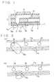
- Fig. 1 is an explanatory view showing a central longitudinal sectional view of the drop discharge device.
- Fig. 2 is an explanatory view showing a bottom surface of a pressurizing chamber of the drop discharge device.
- Fig. 3 is an explanatory view for explaining conditions for arranging different grooves treated for repelling liquid.
- Fig. 4 is an explanatory view for explaining conditions for arranging different grooves treated for repelling liquid.
- Fig. 5 is an explanatory view for particularly defining respective width of drop discharge devices formed by using green sheets
- Fig. 6 is an explanatory view of a nozzle surface wherein a single nozzle is provided for a liquid pressurizing chamber 1.
- Fig. 7 is an explanatory view of a nozzle surface wherein a plurality of nozzles is provided for the liquid pressurizing chamber 1.
- Fig. 8 is an explanatory view of a drop discharge device including a liquid-absorbing layer.
- Fig. 1 is a central longitudinal sectional view of the drop discharge device.
- the drop discharge device comprises a pressurizing means for achieving discharge of liquid such as raw material or fuel, a pressurizing chamber 1 for pressurizing liquid to be discharged, a nozzle 2 connected to a lower portion of the pressurizing chamber 1 for discharging liquid to a processing unit of the raw material/fuel discharge device, a layer treated for repelling liquid 11 disposed in a periphery of a discharge hole 2a of the nozzle 2, and an introducing hole 10 for supplying liquid to the pressurizing chamber 1.
- the layer treated for repelling liquid 11 is composed of a layer treated for repelling liquid 11a formed to extend over the entire bottom surface of the pressurizing chamber 1 and made of fluorocarbon polymers, and grooves treated for repelling liquid 11b engraved in peripheries of the discharge hole 2a.
- Such drop discharge device 7 comprising a single unit, a plurality of such devices is mounted to a raw material/fuel discharge device by units of several to several hundreds, depending on the form of application of the raw material/fuel discharge device, and a plurality of adjoining pressurizing chambers 1, 1 are connected to a common liquid supply path 5 through respective liquid introducing holes 10, and a piezoelectric/ electrostrictive element 9 is provided on a part of an upper wall portion of each liquid pressurizing chamber 1.
- the piezoelectric/electrostrictive element 9 is formed by laminating an upper electrode, a piezoelectric/electrostrictive layer and a lower electrode, and by applying a specified voltage signal, the piezoelectric/electrostrictive layer is deformed through an electric field generated between the upper electrode and the lower electrode, and through pressurizing force generated in the liquid pressurizing chamber 1 for deforming the fixedly attached wall portion of the liquid pressurizing chamber 1, liquid supplied to the liquid pressurizing chamber 1 is accordingly sprayed from the nozzle 2.
- liquid-drop 12a be held on the layer treated for repelling liquid 11a without being scattered, contact of an end portion of the liquid-drop with the grooves treated for repelling liquid 11b as illustrated by liquid-drop 12b, this liquid-drop will flow along the grooves treated for repelling liquid 11b owing to the degraded liquid-repelling properties of the grooves treated for repelling liquid to reduce the size of the liquid-drop to be finally scattered.
- nozzle 2 and the pressurizing chamber 1 of zirconia ceramics By arranging the nozzle 2 and the pressurizing chamber 1 of zirconia ceramics, wettability within the flow paths of the nozzle 2 and the pressurizing chamber 1 with liquid is improved such that air bubbles hardly remain or intermingle, and discharge may be stabilized.
- This can be achieved by forming structural walls of the pressurizing chamber 1 of zirconia ceramics and by forming the nozzle in a piercing manner, while it is possible to coat at least inner walls of the nozzle 2 and the pressurizing chamber 1 with zirconia ceramics.
- Fig. 2 illustrates a bottom surface of the liquid pressurizing chamber 1, wherein grooves treated for repelling liquid 11b are engraved along aligning directions of the discharge holes 2a of the nozzles 2.
- Fig. (a) illustrates a condition in which a liquid-drop 12a is adhering without being scattered, and (b) illustrates liquid-drops 12b that have become smaller along the grooves treated for repelling liquid 11b.
- Figs. 3 and 4 illustrate embodiments of the grooves treated for repelling liquid 11b of different arrangements. While the grooves treated for repelling liquid 11b are disposed along an aligning direction of the discharge holes 2a of the nozzles 2 in Fig. 2, Fig. 3 includes grooves treated for repelling liquid 11b disposed to be orthogonal to the aligning direction of the discharge holes 2a in addition to the grooves treated for repelling liquid 11b disposed along the aligning direction of the discharge holes 2a, wherein overlapping portions 12c duplicated for securing spaces for liquid-drops to flow.
- the grooves treated for repelling liquid 11b of Fig. 4 are disposed to be geometrically symmetric with the discharge holes 2a forming the center, that is, grooves are disposed at equal intervals in scattering directions of liquid-drops. More particularly, (a) is arranged in a radial manner while (b) is arranged in a concentric manner such that distances for making liquid-drops flow may be set longer.
- the layer treated for repelling liquid formed in a periphery of the discharge holes 2a of the nozzles 2 need to be formed only in proximate portions of the nozzles, and portions of different liquid-repelling properties that are formed on these portions may be arranged in that their ends are connected to portions that are not formed with a layer treated for repelling liquids as illustrated in Fig. 3 or in the radial arrangement on the left-hand side of Fig. 4. In this case, it is possible to exhibit an advantage that liquid-drops that have flown out along portions of different liquid-repelling properties can be effectively eliminated from peripheries of the nozzles.
- layer treated for repelling liquid is defined to be a location of inferior properties of wettability with respect to liquid to be discharged than those of materials used for forming the nozzles, and includes fluorocarbon polymers layers, plated layers including fluorine, resin layers including fluorine, silicone resin layer, or a portion made of a same material as that used for forming the nozzles while its surface roughness is arranged to be smooth.
- portions of different liquid-repelling properties may be formed by first forming a layer treated for repelling liquid and thereafter thinning the thickness thereof or omitting it through machine processing or laser processing, by designing the corresponding portions to be thin in thickness or to be omitted simultaneously with forming the first layer, by further overlapping a layer of different liquid-repelling properties onto a readily provided layer, or by stacking the same layer of identical properties for varying the liquid-repelling properties.
- Fig. 5 is an explanatory view for particularly defining respective width of drop discharge devices formed by using green sheets.
- a width of the path of the liquid supply path 5 is defined to be 3.2 mm, a layer thickness thereof to 0.30 mm, a diameter of the introducing hole 10 to 0.034 mm;
- the pressurizing chamber 1 has a chamber length of 3.5 mm and a layer thickness of 0.15 mm;
- the discharge nozzle 2 is formed in a staged manner of different diameters that are defined to be 0.25 mm, 0.15 mm, 0.050 mm, and 0.031 mm, respectively, in this order in approaching the discharge direction.
- maximum liquid-drop diameters d of formed liquid-drops with respect the above-described layer treated for repelling liquid 11a will be as follows, depending on the various materials. It should be noted that a maximum liquid-drop diameter d of a discharged liquid-drop that is formed on the layer treated for repelling liquid is defined to be a liquid-drop diameter obtained in a measuring device with a surface on which the nozzle is formed being provided in a vertical manner and a discharge direction of liquid set in a horizontal manner, wherein a liquid-drop formed on the liquid-repelling surface is deformed from its drop-like shape or is dropped downward.
- distances L from boundaries of portions of different liquid-repelling properties of the layer treated for repelling liquid to an outer periphery of the discharge hole 2a of the nozzle 2 satisfy d>L>0.1d with respect to a maximum liquid-drop diameter d of discharged liquid-drop formed on the layer treated for repelling liquid.
- the type of liquid is gasoline and the layer treated for repelling liquid is formed of fluorocarbon polymers, it is preferable to satisfy 1.5>L>1.5x0.1.
- Figs. 6 and 7 illustrate nozzle surfaces with a plurality of liquid pressurizing chambers 1 of chamber widths of 0.35 mm are provided for a single liquid supply path 5.
- the plurality of liquid pressurizing chambers 1 are connected to the liquid supply path 5 at one ends thereof while a single nozzle 2 is formed on each of the other ends, and a layer treated for repelling liquid 11a is disposed to surround the nozzle 2 in a disk-like manner.
- Each disk-like disposed layer treated for repelling liquid 11a is arranged in that their distances L from the boundaries of portions of different liquid-repelling properties to the outer edges of the discharge holes of the nozzles are identical. Intervals between adjoining nozzles 2 are set to be 0.45 mm.
- the plurality of liquid pressurizing chambers 1 are connected to the liquid supply path 5 at one ends thereof while a plurality of three nozzles 2 are provided at each of the other ends, and layers treated for repelling liquid 11a are disposed to surround each of the nozzles 2 in a disk-like manner.
- Distances M between outer edges of discharges holes of adjoining nozzles 2 will satisfy d ⁇ M with respect to a maximum liquid-drop diameter d of discharged liquid-drops formed on the layers treated for repelling liquid 11a.
- the liquid-drop when the liquid-drop reaches the maximum diameter d, the liquid-drop will vanish through the layer treated for repelling liquid 11a so as to prevent deficiencies in discharge of more than two nozzles caused by a liquid-drop formed by adhering to a single nozzle to further affect the adjoining nozzle.
- a porous liquid-adsorbing layer 13 for absorbing liquid is laminated onto the chamber 1 and preferably extends all around and spaced from the discharge hole 2a of the nozzle 2.
- the liquid-absorbing layer 13 is laminated in a periphery of the nozzle 2 such that the liquid-absorbing layer 13 comes into contact with air, while it is alternatively possible to employ the arrangement of Fig. 8 (b) wherein the layer treated for repelling liquid 11 is formed in the periphery of the nozzle 2 and the liquid-absorbing layer 13 is fixedly attached onto the bottom surface of the pressurizing chamber 1 as to be outwardly aligned to the layer 11.
- the layer treated for repelling liquid is comprised by arranging portions of different liquid-repelling properties in parallel to each other. With this arrangement, liquid-drops that have been discharged from the nozzle and are held on the layer treated for repelling liquid as a large drop without being scattered can be eliminated through portions of different liquid-repelling properties, and it is accordingly possible to prevent deficiencies in discharged owing to liquid-drop residues formed on nozzle discharge outlets.
Landscapes
- Engineering & Computer Science (AREA)
- Chemical & Material Sciences (AREA)
- Combustion & Propulsion (AREA)
- Mechanical Engineering (AREA)
- General Engineering & Computer Science (AREA)
- Nozzles (AREA)
- Particle Formation And Scattering Control In Inkjet Printers (AREA)
Abstract
A drop discharge device has a pressurizing means
(9) for discharge of liquid such as raw material or fuel,
a pressurizing chamber (1) for liquid to be discharged, a
nozzle (2) connected to the pressurizing chamber for
discharging liquid, a layer (11a) for repelling the
liquid disposed adjacent the discharge side of the
nozzle, and an introducing hole (10) for supplying liquid
to the pressurizing chamber. To control liquid drops,
the layer (11a) for repelling liquid has regions of
different liquid-repelling properties and is for example
comprised of a layer treated for repelling liquid formed
to extend over the entire bottom surface of the
pressurizing chamber and made of fluorocarbon polymers,
having grooves (11a) extending around the discharge hole
of the nozzle.
Description
- The present invention relates to a drop discharge device for discharging liquid, such as raw material or fuel for processing or actuating the fluid thereby, for use in a raw material/fuel discharge device of various apparatuses.
- A conventional drop discharge device is comprised of a pressurizing means for achieving discharge of liquid, a pressurizing chamber for achieving discharge of liquid to be discharged, a liquid discharge nozzle connected to the pressurizing chamber, and an introducing hole for supplying liquid to the pressurizing chamber, wherein a plurality of such devices are assembled to a driving means for a raw material/fuel discharge device as units for discharging minute liquid-drops. The liquid introducing holes of the plurality of adjoining drop discharge devices are connected to a common liquid supply path, and piezoelectric/electrostrictive elements are provided on a part of wall portions of the liquid pressuring chambers. For actuating the driving means for the raw material/fuel discharge device, wall portions of the liquid pressurizing chambers are deformed by applying specified voltage signals to the piezoelectric/electrostrictive elements, and through pressure generated in the liquid pressurizing chambers, liquid supplied to the liquid pressuring chambers are sprayed out from the nozzles.
- In case liquid was to be discharged by large amounts in some applications of the raw material/fuel discharge device, the number of nozzles of the plurality of drop discharge devices to be mounted was increased, time intervals for applying the specified voltage signals to the piezoelectric/electrostrictive elements was decreased to thereby improve the number of voltage application per unit time for improving discharge cycles, or voltage to be applied was increased.
- However, in case liquid is to be discharged by large amounts and further in a successive manner as in the above-described case, that is, when a plurality of nozzles, which perform discharge at a flow rate of not less than several tens of pL per one discharge of a single nozzle, at a discharge cycle of not less than several kHz, and for not less than several tens of ms, are provided at distances of several hundreds of µm, liquid-drops will remain in the nozzles or peripheries thereof to result in unstable discharge or phenomena in which discharge is absorbed by liquid-drops to make spraying impossible.
- Thus, the inventors of the present invention have devised, according to the invention, a drop discharge device comprising a pressurizing means for achieving discharge of liquid, a pressurizing chamber for pressurizing the liquid to be discharged, a liquid discharge nozzle connectedly provided to the liquid pressurizing chamber, and a layer treated for repelling liquid disposed on a periphery of a discharge hole of the nozzle, wherein the layer treated for repelling liquid is comprised by arranging portions of different liquid-repelling properties in parallel to each other. With this arrangement, liquid-drops that have been discharged from the nozzle but remaining as large liquid-drops on the layer treated for repelling liquid without being scattered will be eliminated at portions of different liquid-repelling properties, and discharge deficiencies caused through liquid-drop residues at the nozzle discharge outlet will be prevented.
- The layer for repelling liquid comprised by arranging portions of different liquid-repelling properties may, in addition to a first liquid-repelling layer disposed in a periphery of the discharge hole of the nozzle, at least a second liquid-repelling layer connected to an outer edge of the first liquid-repelling layer, wherein liquid-repelling properties of the second liquid-repelling layer of different liquid-repelling properties may be either superior or inferior than those of the first liquid-repelling layer.
- In one aspect of the invention, portions with inferior liquid-repelling properties from among the portions of different liquid-repelling properties of the layer treated for repelling liquid may be formed by omitting the layer for repelling liquid at the stage of designing or by thinning the layer thickness or partially omitting the layer treated for repelling liquid by performing cutting, dissolving or decomposing after forming. For example, portions with inferior liquid-repelling properties from among the portions of different liquid-repelling properties of the layer for repelling liquid are formed by cutting, dissolving or decomposing the layer treated for repelling liquid to assume concave sections. Alternatively, portions of different liquid-repelling properties of the layer for repelling liquid being formed of a layer treated for repelling liquid made of a material with different liquid-repelling properties.
- Suitably distances L from boundaries of portions of different liquid-repelling properties of the layer for repelling liquid to an outer periphery of the discharge hole of the nozzle are identical to each other. With this arrangement, liquid-drops will contact boundaries of portions of different liquid-repelling properties regardless of an expanding direction of the liquid-drops so that liquid may be reliably emitted.
- The distance L from boundaries of portions of different liquid-repelling properties of the layer treated for repelling liquid to the outer periphery of the discharge hole of the nozzle is preferably in a range of 200 to 500 µm. In case the distance L is not less than 200 µm, exact positioning to the outer edge of the discharge hole of the nozzle is enabled, a layer thickness thereof made large to be hard to peel off, and a liquid-repelling layer of high durability can be obtained. Since the distance L is further not more than 500 µm which is a maximum diameter of a general liquid-drop causing unstable discharge of the nozzle, liquid-drops in larger conditions will contact portions of different liquid-repelling properties to be eliminated, and it is accordingly possible to prevent discharge deficiencies owing to liquid-drops remaining in the nozzle discharge outlet.
- Preferably distances L from boundaries of portions of different liquid-repelling properties of the layer treated for repelling liquid to an outer periphery of the discharge hole of the nozzle satisfy d>L>0.1d with respect to a maximum liquid-drop diameter d of a discharged liquid-drop formed on the layer for repelling liquid.
- Here, the maximum liquid-drop diameter d of discharged liquid formed on the layer treated for repelling liquid is a liquid-drop diameter obtained in a measuring device with a surface on which the nozzle is formed being provided in a vertical manner and a discharge direction of liquid-drops set in a horizontal manner, when a liquid-drop formed on the liquid-repelling surface is deformed from its drop-like shape or is dropped downward.
- Suitably a plurality of nozzles are provided with a pressurizing chamber with distances M between outer peripheries of discharge holes of adjoining nozzles satisfy d<M with respect to a maximum liquid-drop diameter d of a discharged liquid-drop formed on the layer treated for repelling liquid.
- In an embodiment wherein liquid-repelling properties of a second liquid-repelling layer of different liquid-repelling properties are inferior than those of the first liquid-repelling layer, the drop discharge device may be arranged in that a porous liquid absorbing layer is disposed on a periphery of the layer treated for repelling liquid. With this arrangement, even if liquid-drop remaining in the nozzle discharge outlet to cause discharge deficiencies shall be come large, this liquid-drop will be penetrated upon contacting the liquid absorbing layer so that the liquid-drop that has become smaller will be reduced to a size similar to those at peripheries of the discharge hole of the nozzle.
- Preferably the nozzle(s) and pressurizing chamber are made of zirconia ceramics. With this arrangement, wettability of flow paths within the nozzle and the pressuring chamber with fluid will be improved such that air bubbles hardly remain or intermingle, and discharge may be stabilized.
- The invention in further aspects is set out in
claims - Fig. 1 is an explanatory view showing a central longitudinal sectional view of the drop discharge device.
- Fig. 2 is an explanatory view showing a bottom surface of a pressurizing chamber of the drop discharge device.
- Fig. 3 is an explanatory view for explaining conditions for arranging different grooves treated for repelling liquid.
- Fig. 4 is an explanatory view for explaining conditions for arranging different grooves treated for repelling liquid.
- Fig. 5 is an explanatory view for particularly defining respective width of drop discharge devices formed by using green sheets
- Fig. 6 is an explanatory view of a nozzle surface wherein a single nozzle is provided for a liquid pressurizing
chamber 1. - Fig. 7 is an explanatory view of a nozzle surface wherein a plurality of nozzles is provided for the liquid pressurizing
chamber 1. - Fig. 8 is an explanatory view of a drop discharge device including a liquid-absorbing layer.
- Forms for embodying the drop discharge device according to the present invention will now be explained in detail.
- Fig. 1 is a central longitudinal sectional view of the drop discharge device. The drop discharge device comprises a pressurizing means for achieving discharge of liquid such as raw material or fuel, a pressurizing
chamber 1 for pressurizing liquid to be discharged, anozzle 2 connected to a lower portion of the pressurizingchamber 1 for discharging liquid to a processing unit of the raw material/fuel discharge device, a layer treated for repellingliquid 11 disposed in a periphery of adischarge hole 2a of thenozzle 2, and an introducinghole 10 for supplying liquid to the pressurizingchamber 1. The layer treated for repellingliquid 11 is composed of a layer treated for repellingliquid 11a formed to extend over the entire bottom surface of the pressurizingchamber 1 and made of fluorocarbon polymers, and grooves treated for repellingliquid 11b engraved in peripheries of thedischarge hole 2a. - Such
drop discharge device 7 comprising a single unit, a plurality of such devices is mounted to a raw material/fuel discharge device by units of several to several hundreds, depending on the form of application of the raw material/fuel discharge device, and a plurality of adjoiningpressurizing chambers liquid supply path 5 through respectiveliquid introducing holes 10, and a piezoelectric/electrostrictive element 9 is provided on a part of an upper wall portion of each liquid pressurizingchamber 1. The piezoelectric/electrostrictive element 9 is formed by laminating an upper electrode, a piezoelectric/electrostrictive layer and a lower electrode, and by applying a specified voltage signal, the piezoelectric/electrostrictive layer is deformed through an electric field generated between the upper electrode and the lower electrode, and through pressurizing force generated in the liquid pressurizingchamber 1 for deforming the fixedly attached wall portion of the liquid pressurizingchamber 1, liquid supplied to the liquid pressurizingchamber 1 is accordingly sprayed from thenozzle 2. - At this time, should liquid-
drop 12a be held on the layer treated for repellingliquid 11a without being scattered, contact of an end portion of the liquid-drop with the grooves treated for repellingliquid 11b as illustrated by liquid-drop 12b, this liquid-drop will flow along the grooves treated for repellingliquid 11b owing to the degraded liquid-repelling properties of the grooves treated for repelling liquid to reduce the size of the liquid-drop to be finally scattered. - By arranging the
nozzle 2 and the pressurizingchamber 1 of zirconia ceramics, wettability within the flow paths of thenozzle 2 and the pressurizingchamber 1 with liquid is improved such that air bubbles hardly remain or intermingle, and discharge may be stabilized. This can be achieved by forming structural walls of the pressurizingchamber 1 of zirconia ceramics and by forming the nozzle in a piercing manner, while it is possible to coat at least inner walls of thenozzle 2 and the pressurizingchamber 1 with zirconia ceramics. - Fig. 2 illustrates a bottom surface of the liquid pressurizing
chamber 1, wherein grooves treated for repellingliquid 11b are engraved along aligning directions of thedischarge holes 2a of thenozzles 2. Fig. (a) illustrates a condition in which a liquid-drop 12a is adhering without being scattered, and (b) illustrates liquid-drops 12b that have become smaller along the grooves treated for repellingliquid 11b. - Figs. 3 and 4 illustrate embodiments of the grooves treated for repelling liquid 11b of different arrangements. While the grooves treated for repelling
liquid 11b are disposed along an aligning direction of thedischarge holes 2a of thenozzles 2 in Fig. 2, Fig. 3 includes grooves treated for repellingliquid 11b disposed to be orthogonal to the aligning direction of thedischarge holes 2a in addition to the grooves treated for repellingliquid 11b disposed along the aligning direction of thedischarge holes 2a, wherein overlappingportions 12c duplicated for securing spaces for liquid-drops to flow. - The grooves treated for repelling
liquid 11b of Fig. 4 are disposed to be geometrically symmetric with thedischarge holes 2a forming the center, that is, grooves are disposed at equal intervals in scattering directions of liquid-drops. More particularly, (a) is arranged in a radial manner while (b) is arranged in a concentric manner such that distances for making liquid-drops flow may be set longer. - Further, as illustrated in Figs. 3 and 4, the layer treated for repelling liquid formed in a periphery of the
discharge holes 2a of thenozzles 2 need to be formed only in proximate portions of the nozzles, and portions of different liquid-repelling properties that are formed on these portions may be arranged in that their ends are connected to portions that are not formed with a layer treated for repelling liquids as illustrated in Fig. 3 or in the radial arrangement on the left-hand side of Fig. 4. In this case, it is possible to exhibit an advantage that liquid-drops that have flown out along portions of different liquid-repelling properties can be effectively eliminated from peripheries of the nozzles. - The term "layer treated for repelling liquid" is defined to be a location of inferior properties of wettability with respect to liquid to be discharged than those of materials used for forming the nozzles, and includes fluorocarbon polymers layers, plated layers including fluorine, resin layers including fluorine, silicone resin layer, or a portion made of a same material as that used for forming the nozzles while its surface roughness is arranged to be smooth.
- The "portions of different liquid-repelling properties" that are formed thereat may be formed by first forming a layer treated for repelling liquid and thereafter thinning the thickness thereof or omitting it through machine processing or laser processing, by designing the corresponding portions to be thin in thickness or to be omitted simultaneously with forming the first layer, by further overlapping a layer of different liquid-repelling properties onto a readily provided layer, or by stacking the same layer of identical properties for varying the liquid-repelling properties.
- Fig. 5 is an explanatory view for particularly defining respective width of drop discharge devices formed by using green sheets. A width of the path of the
liquid supply path 5 is defined to be 3.2 mm, a layer thickness thereof to 0.30 mm, a diameter of the introducinghole 10 to 0.034 mm; the pressurizingchamber 1 has a chamber length of 3.5 mm and a layer thickness of 0.15 mm; thedischarge nozzle 2 is formed in a staged manner of different diameters that are defined to be 0.25 mm, 0.15 mm, 0.050 mm, and 0.031 mm, respectively, in this order in approaching the discharge direction. - Values of maximum liquid-drop diameters d of formed liquid-drops with respect the above-described layer treated for repelling
liquid 11a will be as follows, depending on the various materials. It should be noted that a maximum liquid-drop diameter d of a discharged liquid-drop that is formed on the layer treated for repelling liquid is defined to be a liquid-drop diameter obtained in a measuring device with a surface on which the nozzle is formed being provided in a vertical manner and a discharge direction of liquid set in a horizontal manner, wherein a liquid-drop formed on the liquid-repelling surface is deformed from its drop-like shape or is dropped downward.
- It is evident from these measured values that distances L from boundaries of portions of different liquid-repelling properties of the layer treated for repelling liquid to an outer periphery of the
discharge hole 2a of thenozzle 2 satisfy d>L>0.1d with respect to a maximum liquid-drop diameter d of discharged liquid-drop formed on the layer treated for repelling liquid. For instance, in case the type of liquid is gasoline and the layer treated for repelling liquid is formed of fluorocarbon polymers, it is preferable to satisfy 1.5>L>1.5x0.1. In case L is smaller than 0.1d, forming of the layer treated for repelling liquid may be difficult and liquid-repelling properties may be degraded owing to a shift in position with respect to the nozzle, while in case L is larger than d, liquid-drops will continuously reside in proximities of the nozzle to be a hindrance for the following discharge of liquid-drops and thus to cause deficiencies in spraying. - Figs. 6 and 7 illustrate nozzle surfaces with a plurality of
liquid pressurizing chambers 1 of chamber widths of 0.35 mm are provided for a singleliquid supply path 5. - In Fig. 6, the plurality of
liquid pressurizing chambers 1 are connected to theliquid supply path 5 at one ends thereof while asingle nozzle 2 is formed on each of the other ends, and a layer treated for repelling liquid 11a is disposed to surround thenozzle 2 in a disk-like manner. Each disk-like disposed layer treated for repelling liquid 11a is arranged in that their distances L from the boundaries of portions of different liquid-repelling properties to the outer edges of the discharge holes of the nozzles are identical. Intervals between adjoiningnozzles 2 are set to be 0.45 mm. - On the other hand, in Fig. 7, the plurality of
liquid pressurizing chambers 1 are connected to theliquid supply path 5 at one ends thereof while a plurality of threenozzles 2 are provided at each of the other ends, and layers treated for repelling liquid 11a are disposed to surround each of thenozzles 2 in a disk-like manner. Distances M between outer edges of discharges holes of adjoiningnozzles 2 will satisfy d<M with respect to a maximum liquid-drop diameter d of discharged liquid-drops formed on the layers treated for repelling liquid 11a. In this manner, when the liquid-drop reaches the maximum diameter d, the liquid-drop will vanish through the layer treated for repelling liquid 11a so as to prevent deficiencies in discharge of more than two nozzles caused by a liquid-drop formed by adhering to a single nozzle to further affect the adjoining nozzle. - In Fig. 8, a porous liquid-adsorbing
layer 13 for absorbing liquid is laminated onto thechamber 1 and preferably extends all around and spaced from thedischarge hole 2a of thenozzle 2. With this arrangement, liquid-drops once remaining in the periphery of thenozzle 2 are absorbed by the liquid-absorbinglayer 13 so that no liquid-drops will remain in the periphery of thenozzle 2 any more, while the absorbed liquid will be gradually evaporated from its surface owing to the porous properties of the liquid-absorbinglayer 13 so that remaining liquid-drops will be continuously absorbed. It should be noted that in Fig. 8(a), the liquid-absorbinglayer 13 is laminated in a periphery of thenozzle 2 such that the liquid-absorbinglayer 13 comes into contact with air, while it is alternatively possible to employ the arrangement of Fig. 8 (b) wherein the layer treated for repellingliquid 11 is formed in the periphery of thenozzle 2 and the liquid-absorbinglayer 13 is fixedly attached onto the bottom surface of the pressurizingchamber 1 as to be outwardly aligned to thelayer 11. - As it has been explained so far, according to the present invention of
Claim 1, the layer treated for repelling liquid is comprised by arranging portions of different liquid-repelling properties in parallel to each other. With this arrangement, liquid-drops that have been discharged from the nozzle and are held on the layer treated for repelling liquid as a large drop without being scattered can be eliminated through portions of different liquid-repelling properties, and it is accordingly possible to prevent deficiencies in discharged owing to liquid-drop residues formed on nozzle discharge outlets. It is further possible to prevent occurrence of discharge deficiencies owing to changes in volume of air-bubble portions through pressurizing at the time of filling liquid into the entire flow path including the pressurizing chamber caused through air-bubbles residues being pinched between liquid remaining in the nozzle discharge outlet and liquid supplied by starting discharge.
Claims (13)
- A drop discharge device for discharging liquid, comprising a pressurizing means (9) for achieving discharge of liquid, a pressurizing chamber (1) for pressurizing the liquid to be discharged, a liquid discharge nozzle (2) connected to the liquid pressurizing chamber, and a layer (11a) for repelling the liquid disposed around the discharge hole (2) of the nozzle, characterized in that the layer (11a) for repelling liquid has portions (11b) of different liquid-repelling properties spaced from each other.
- The drop discharge device of Claim 1, wherein portions (11b) with inferior liquid-repelling properties from among the portions of different liquid-repelling properties of the layer (11a) are formed by gaps of the layer (11a).
- The drop discharge device device of Claim 1, wherein portions (11b) with inferior liquid-repelling properties from among the portions of different liquid-repelling properties of the layer (11a) are formed by concave regions of the layer (11a).
- The drop discharge device of Claim 1, wherein the portions (11b) of different liquid-repelling properties of the layer (11a) are formed of a layer for repelling liquid made of a material with different liquid-repelling properties.
- The drop discharge device of any one of Claims 1 to 4, wherein distances L from boundaries of portions of different liquid-repelling properties of the layer for repelling liquid to an outer periphery of the discharge hole of the nozzle are identical to each other.
- The drop discharge device of any one of Claims 1 to 5, wherein distances L from boundaries of portions of different liquid-repelling properties of the layer for repelling liquid to an outer periphery of the discharge hole of the nozzle satisfy d>L>0.1d with respect to a maximum liquid-drop diameter d of a discharged liquid-drop formed on the layer for repelling liquid.
- The drop discharge device of any one of Claims 1 to 6, wherein a plurality of nozzles are provided with distances M between outer peripheries of discharge holes of adjoining nozzles which satisfy d<M with respect to a maximum liquid-drop diameter d of a discharged liquid-drop formed on the layer for repelling liquid.
- The drop discharge device of any one of Claims 1 to 7, wherein a porous liquid absorbing layer (13) is disposed on the layer (11a) for repelling liquid.
- The drop discharge device of Claim 8 wherein the absorbing layer (13) extends around the nozzle discharge opening and is spaced therefrom.
- The drop discharge device of any one of Claims1 to 9, wherein the nozzle(s) and pressurizing chamber are made of zirconia ceramics.
- A drop discharge device for discharging liquid, comprising a pressurizing means (9) for achieving discharge of liquid, a pressurizing chamber (1) for pressurizing the liquid to be discharged, a liquid discharge nozzle (2) connected to the liquid pressurizing chamber, characterized by a porous liquid absorbing layer (13) arranged adjacent the nozzle discharge opening.
- The drop discharge device of Claim 11 wherein the absorbing layer (13) extends around the nozzle discharge opening and is spaced therefrom.
- Liquid dispensing apparatus having one or more drop discharge devices according to any one of the preceding claims.
Applications Claiming Priority (2)
| Application Number | Priority Date | Filing Date | Title |
|---|---|---|---|
| JP2000185494 | 2000-06-20 | ||
| JP2000185494 | 2000-06-20 |
Publications (1)
| Publication Number | Publication Date |
|---|---|
| EP1166887A2 true EP1166887A2 (en) | 2002-01-02 |
Family
ID=18685808
Family Applications (2)
| Application Number | Title | Priority Date | Filing Date |
|---|---|---|---|
| EP01305130A Withdrawn EP1166887A2 (en) | 2000-06-20 | 2001-06-13 | Liquid drop discharge device |
| EP01941088A Withdrawn EP1293257A1 (en) | 2000-06-20 | 2001-06-19 | Liquid droplet ejecting device and liquid droplet ejecting method |
Family Applications After (1)
| Application Number | Title | Priority Date | Filing Date |
|---|---|---|---|
| EP01941088A Withdrawn EP1293257A1 (en) | 2000-06-20 | 2001-06-19 | Liquid droplet ejecting device and liquid droplet ejecting method |
Country Status (3)
| Country | Link |
|---|---|
| US (3) | US6474566B1 (en) |
| EP (2) | EP1166887A2 (en) |
| WO (1) | WO2001097977A1 (en) |
Cited By (3)
| Publication number | Priority date | Publication date | Assignee | Title |
|---|---|---|---|---|
| EP1468749A1 (en) * | 2003-04-15 | 2004-10-20 | Microflow Engineering SA | Low-cost liquid droplet spray device and nozzle body |
| WO2005010349A1 (en) * | 2003-07-02 | 2005-02-03 | Robert Bosch Gmbh | Fuel injection value and method for producing the same |
| EP1385000A4 (en) * | 2001-05-01 | 2006-04-19 | Ngk Insulators Ltd | Method for making biochip |
Families Citing this family (44)
| Publication number | Priority date | Publication date | Assignee | Title |
|---|---|---|---|---|
| US6875402B2 (en) * | 2000-10-16 | 2005-04-05 | Ngk Insulators, Ltd. | Micropipette, dispenser and method for producing biochip |
| DE10065855A1 (en) * | 2000-12-22 | 2002-07-04 | Bsh Bosch Siemens Hausgeraete | Dosing device for conveying small quantities of substances |
| US20030116641A1 (en) * | 2001-10-02 | 2003-06-26 | Ngk Insulators, Ltd. | Liquid injection apparatus |
| JP2003214302A (en) * | 2001-11-16 | 2003-07-30 | Ngk Insulators Ltd | Liquid fuel injection device |
| JP2004052619A (en) * | 2002-07-18 | 2004-02-19 | Ngk Insulators Ltd | Liquid injection device |
| US6764023B2 (en) * | 2002-10-09 | 2004-07-20 | Industrial Technology Research Institute | Bi-direction pumping droplet mist ejection apparatus |
| JP2005074767A (en) * | 2003-08-29 | 2005-03-24 | Matsushita Electric Ind Co Ltd | Inkjet recording device |
| US7357482B2 (en) * | 2004-03-31 | 2008-04-15 | Brother Kogyo Kabushiki Kaisha | Liquid droplet-ejecting apparatus, ink-jet printer, and liquid droplet-moving apparatus |
| US20050268845A1 (en) * | 2004-06-03 | 2005-12-08 | Nordson Corporation | Apparatus and nozzle plate for dispensing liquid material |
| US20050271806A1 (en) * | 2004-06-03 | 2005-12-08 | Nordson Corporation | Dispenser and method for non-contact dispensing of adhesive |
| DE102004049280A1 (en) * | 2004-10-09 | 2006-04-13 | Robert Bosch Gmbh | Fuel injector |
| JP4902971B2 (en) * | 2005-06-27 | 2012-03-21 | 富士フイルム株式会社 | Liquid discharge head |
| WO2007016175A1 (en) * | 2005-07-28 | 2007-02-08 | Guasch Michael N | Fuel repellent compositions, fabrics and articles |
| TWI265095B (en) * | 2005-08-16 | 2006-11-01 | Ind Tech Res Inst | Nozzle plate |
| TWI294789B (en) * | 2005-11-29 | 2008-03-21 | Ind Tech Res Inst | Droplet ejecting head |
| JP2007177766A (en) * | 2005-12-28 | 2007-07-12 | Toyota Motor Corp | Fuel injection device |
| TWI290485B (en) * | 2005-12-30 | 2007-12-01 | Ind Tech Res Inst | Spraying device |
| US7712680B2 (en) * | 2006-01-30 | 2010-05-11 | Sono-Tek Corporation | Ultrasonic atomizing nozzle and method |
| US8171973B2 (en) * | 2008-01-29 | 2012-05-08 | Nordson Corporation | Nozzle and related apparatus and method for dispensing molten thermoplastic material |
| JP2009207650A (en) * | 2008-03-04 | 2009-09-17 | Panasonic Corp | Electric power device, electronic device using the same, and power supply element inspection facility |
| US9272297B2 (en) * | 2008-03-04 | 2016-03-01 | Sono-Tek Corporation | Ultrasonic atomizing nozzle methods for the food industry |
| US8210674B2 (en) * | 2008-03-31 | 2012-07-03 | Brother Kogyo Kabushiki Kaisha | Liquid droplet jetting apparatus |
| JP5339842B2 (en) * | 2008-10-06 | 2013-11-13 | キヤノン株式会社 | Discharge head and droplet discharge device |
| KR20100114335A (en) * | 2009-04-15 | 2010-10-25 | 삼성전기주식회사 | Inkjet head |
| JP5343869B2 (en) * | 2010-01-15 | 2013-11-13 | セイコーエプソン株式会社 | Gel production equipment |
| US9975136B2 (en) | 2011-06-08 | 2018-05-22 | Pari Pharma Gmbh | Aerosol generator |
| US8876255B2 (en) * | 2012-07-31 | 2014-11-04 | Hewlett-Packard Development Company, L.P. | Orifice structure for fluid ejection device and method of forming same |
| US10066114B2 (en) | 2012-09-14 | 2018-09-04 | The Procter & Gamble Company | Ink jet delivery system comprising an improved perfume mixture |
| JP6271905B2 (en) * | 2013-08-07 | 2018-01-31 | キヤノン株式会社 | Liquid discharge head, liquid discharge apparatus, and method of manufacturing liquid discharge head |
| JP5934161B2 (en) * | 2013-09-09 | 2016-06-15 | 武蔵エンジニアリング株式会社 | Nozzle and liquid material discharge apparatus including the nozzle |
| US9433696B2 (en) | 2014-06-20 | 2016-09-06 | The Procter & Gamble Company | Microfluidic delivery system for releasing fluid compositions |
| US10076585B2 (en) | 2014-06-20 | 2018-09-18 | The Procter & Gamble Company | Method of delivering a dose of a fluid composition from a microfluidic delivery cartridge |
| US9211980B1 (en) | 2014-06-20 | 2015-12-15 | The Procter & Gamble Company | Microfluidic delivery system for releasing fluid compositions |
| US9808812B2 (en) | 2014-06-20 | 2017-11-07 | The Procter & Gamble Company | Microfluidic delivery system |
| US9744549B2 (en) * | 2015-03-16 | 2017-08-29 | The Procter & Gamble Company | System and method for dispensing material |
| US10780192B2 (en) | 2015-09-16 | 2020-09-22 | The Procter & Gamble Company | Microfluidic delivery cartridges and methods of connecting cartridges with microfluidic delivery systems |
| JP6707849B2 (en) * | 2015-12-09 | 2020-06-10 | セイコーエプソン株式会社 | Inkjet recording method |
| CN109073515B (en) * | 2016-03-31 | 2021-04-06 | 惠普发展公司,有限责任合伙企业 | Monolithic carrier structure including fluid routing for digital distribution |
| US10149917B2 (en) | 2016-11-22 | 2018-12-11 | The Procter & Gamble Company | Fluid composition and a microfluidic delivery cartridge comprising the same |
| US11305301B2 (en) | 2017-04-10 | 2022-04-19 | The Procter & Gamble Company | Microfluidic delivery device for dispensing and redirecting a fluid composition in the air |
| US12103020B2 (en) | 2017-04-10 | 2024-10-01 | The Procter & Gamble Company | Microfluidic delivery device and method for dispensing a fluid composition upward into the air |
| US11691162B2 (en) | 2017-04-10 | 2023-07-04 | The Procter & Gamble Company | Microfluidic delivery cartridge for use with a microfluidic delivery device |
| JP2019100208A (en) * | 2017-11-29 | 2019-06-24 | 株式会社デンソー | Fuel injection valve |
| US10806816B2 (en) | 2018-05-15 | 2020-10-20 | The Procter & Gamble Company | Microfluidic cartridge and microfluidic delivery device comprising the same |
Family Cites Families (23)
| Publication number | Priority date | Publication date | Assignee | Title |
|---|---|---|---|---|
| GB1552419A (en) * | 1975-08-20 | 1979-09-12 | Plessey Co Ltd | Fuel injection system |
| JPS5490416A (en) | 1977-12-27 | 1979-07-18 | Mikuni Kogyo Co Ltd | Method of supplying fuel to internal combustion engine |
| JPS6022065A (en) | 1983-07-19 | 1985-02-04 | Hitachi Metals Ltd | Fuel injector |
| JPS6111451A (en) | 1984-06-26 | 1986-01-18 | Mitsubishi Motors Corp | Fuel injection device |
| GB2203994B (en) * | 1987-03-31 | 1991-12-11 | Canon Kk | Liquid injection recording apparatus and liquid-repellent process method used for the apparatus |
| US4907748A (en) * | 1988-08-12 | 1990-03-13 | Ford Motor Company | Fuel injector with silicon nozzle |
| US5152456A (en) * | 1989-12-12 | 1992-10-06 | Bespak, Plc | Dispensing apparatus having a perforate outlet member and a vibrating device |
| JPH0424657A (en) | 1990-05-18 | 1992-01-28 | Mita Ind Co Ltd | Image forming device |
| JPH0424657U (en) * | 1990-06-22 | 1992-02-27 | ||
| JPH04134176A (en) | 1990-09-26 | 1992-05-08 | Mazda Motor Corp | Fuel injecting device for engine |
| EP0494693B1 (en) * | 1991-01-11 | 1998-04-01 | Canon Kabushiki Kaisha | Ink jet recording apparatus |
| JP3278186B2 (en) * | 1991-03-08 | 2002-04-30 | キヤノン株式会社 | Inkjet recording head |
| US5248087A (en) * | 1992-05-08 | 1993-09-28 | Dressler John L | Liquid droplet generator |
| JPH0655739A (en) * | 1992-08-03 | 1994-03-01 | Seiko Epson Corp | Inkjet recording head |
| JPH06297719A (en) * | 1993-04-16 | 1994-10-25 | Brother Ind Ltd | Liquid droplet jet device and production thereof |
| GB9412669D0 (en) * | 1994-06-23 | 1994-08-10 | The Technology Partnership Plc | Liquid spray apparatus |
| US5437255A (en) | 1994-03-15 | 1995-08-01 | Sadley; Mark L. | Fuel injection sytem employing solid-state injectors for liquid fueled combustion engines |
| US5840062A (en) | 1995-11-08 | 1998-11-24 | Gumaste; Anand V. | Solid state fluid delivery system |
| US5713333A (en) * | 1996-10-21 | 1998-02-03 | Cummins Engine Company, Inc. | Wear-resistant fuel distributor rotor |
| JP3570895B2 (en) * | 1998-07-02 | 2004-09-29 | 日本碍子株式会社 | Discharge device for raw materials and fuel |
| JP3352949B2 (en) * | 1998-07-03 | 2002-12-03 | 日本碍子株式会社 | Material / fuel discharge device |
| JP2000052552A (en) * | 1998-08-07 | 2000-02-22 | Olympus Optical Co Ltd | Droplet ejector |
| JP2001024248A (en) * | 1999-07-07 | 2001-01-26 | Samsung Electro Mech Co Ltd | Method of manufacturing multilayer piezoelectric / electrostrictive ceramic actuator by low-temperature firing method and multilayer piezoelectric / electrostrictive ceramic actuator manufactured by the method |
-
2000
- 2000-06-28 US US09/606,380 patent/US6474566B1/en not_active Expired - Fee Related
-
2001
- 2001-06-13 EP EP01305130A patent/EP1166887A2/en not_active Withdrawn
- 2001-06-19 EP EP01941088A patent/EP1293257A1/en not_active Withdrawn
- 2001-06-19 US US09/884,457 patent/US6752326B2/en not_active Expired - Fee Related
- 2001-06-19 WO PCT/JP2001/005214 patent/WO2001097977A1/en not_active Ceased
-
2004
- 2004-02-05 US US10/772,825 patent/US20040173693A1/en not_active Abandoned
Cited By (4)
| Publication number | Priority date | Publication date | Assignee | Title |
|---|---|---|---|---|
| EP1385000A4 (en) * | 2001-05-01 | 2006-04-19 | Ngk Insulators Ltd | Method for making biochip |
| US7160512B2 (en) | 2001-05-01 | 2007-01-09 | Ngk Insulators, Ltd. | Method for manufacturing biochips |
| EP1468749A1 (en) * | 2003-04-15 | 2004-10-20 | Microflow Engineering SA | Low-cost liquid droplet spray device and nozzle body |
| WO2005010349A1 (en) * | 2003-07-02 | 2005-02-03 | Robert Bosch Gmbh | Fuel injection value and method for producing the same |
Also Published As
| Publication number | Publication date |
|---|---|
| WO2001097977A1 (en) | 2001-12-27 |
| US6474566B1 (en) | 2002-11-05 |
| US6752326B2 (en) | 2004-06-22 |
| US20020050533A1 (en) | 2002-05-02 |
| EP1293257A1 (en) | 2003-03-19 |
| US20040173693A1 (en) | 2004-09-09 |
Similar Documents
| Publication | Publication Date | Title |
|---|---|---|
| US6474566B1 (en) | Drop discharge device | |
| US8535756B2 (en) | Method for dispensing random pattern of adhesive filaments | |
| CN106113940B (en) | Fluid ejection head and the recording device using the fluid ejection head | |
| KR20100067098A (en) | Apparatus for anisotropic focusing | |
| EP1155745A2 (en) | Module and nozzle for dispensing controlled patterns of liquid material | |
| EP1077331A2 (en) | Liquid drop spraying apparatus | |
| JPH06218929A (en) | Actuator and ink jet print head using same | |
| KR20080064606A (en) | Piezoelectric inkjet head and its manufacturing method | |
| CN103373071A (en) | Formation of a funnel-shaped nozzle | |
| KR20050054962A (en) | Liquid jetting device | |
| CN101415560A (en) | Liquid discharge device | |
| JP2020521633A (en) | Nozzle device and manufacturing method thereof | |
| JP2001232245A (en) | Liquid ejection head | |
| CN117769495B (en) | Manufacturing method of nozzle plate, droplet discharge head, droplet discharge device and nozzle plate | |
| JP5107891B2 (en) | Droplet ejection device | |
| KR20220020283A (en) | Microfluidic device and its manufacturing method | |
| US7175108B2 (en) | Applicator and nozzle for dispensing controlled patterns of liquid material | |
| TWI294789B (en) | Droplet ejecting head | |
| US7608988B2 (en) | Cylindrical piezoelectric unit and printer head having the same | |
| JP2002086021A (en) | Droplet ejection device | |
| JP2010269219A (en) | Nozzle and method for forming coating film | |
| US7543919B2 (en) | Liquid transport apparatus and method for producing the same | |
| JP7287451B2 (en) | Nozzle plate and manufacturing method thereof | |
| GB2482873A (en) | Droplet generator for dispensing multiple streams of uniform liquid droplets | |
| JP2000279856A (en) | Droplet ejection device |
Legal Events
| Date | Code | Title | Description |
|---|---|---|---|
| PUAI | Public reference made under article 153(3) epc to a published international application that has entered the european phase |
Free format text: ORIGINAL CODE: 0009012 |
|
| AK | Designated contracting states |
Kind code of ref document: A2 Designated state(s): AT BE CH CY DE DK ES FI FR GB GR IE IT LI LU MC NL PT SE TR |
|
| AX | Request for extension of the european patent |
Free format text: AL;LT;LV;MK;RO;SI |
|
| STAA | Information on the status of an ep patent application or granted ep patent |
Free format text: STATUS: THE APPLICATION HAS BEEN WITHDRAWN |
|
| 18W | Application withdrawn |
Effective date: 20030408 |