EP1164784A1 - Preventing doming phenomena - Google Patents
Preventing doming phenomena Download PDFInfo
- Publication number
- EP1164784A1 EP1164784A1 EP00202057A EP00202057A EP1164784A1 EP 1164784 A1 EP1164784 A1 EP 1164784A1 EP 00202057 A EP00202057 A EP 00202057A EP 00202057 A EP00202057 A EP 00202057A EP 1164784 A1 EP1164784 A1 EP 1164784A1
- Authority
- EP
- European Patent Office
- Prior art keywords
- circuit
- histogram
- luminance
- beam current
- circuit according
- Prior art date
- Legal status (The legal status is an assumption and is not a legal conclusion. Google has not performed a legal analysis and makes no representation as to the accuracy of the status listed.)
- Withdrawn
Links
- 238000012937 correction Methods 0.000 claims abstract description 35
- 238000012545 processing Methods 0.000 claims abstract description 13
- 238000000034 method Methods 0.000 claims abstract description 5
- 230000015654 memory Effects 0.000 claims description 17
- 238000010894 electron beam technology Methods 0.000 claims description 6
- 230000002265 prevention Effects 0.000 claims description 4
- 241000255969 Pieris brassicae Species 0.000 claims 1
- 230000006870 function Effects 0.000 description 3
- 238000005259 measurement Methods 0.000 description 3
- 230000001419 dependent effect Effects 0.000 description 2
- 230000000694 effects Effects 0.000 description 2
- 230000003213 activating effect Effects 0.000 description 1
- 238000004364 calculation method Methods 0.000 description 1
- 238000004040 coloring Methods 0.000 description 1
- 238000010276 construction Methods 0.000 description 1
- 230000001186 cumulative effect Effects 0.000 description 1
- 230000003247 decreasing effect Effects 0.000 description 1
- 238000013461 design Methods 0.000 description 1
- 238000010586 diagram Methods 0.000 description 1
- 238000001914 filtration Methods 0.000 description 1
Images

Classifications
-
- H—ELECTRICITY
- H04—ELECTRIC COMMUNICATION TECHNIQUE
- H04N—PICTORIAL COMMUNICATION, e.g. TELEVISION
- H04N5/00—Details of television systems
- H04N5/44—Receiver circuitry for the reception of television signals according to analogue transmission standards
- H04N5/57—Control of contrast or brightness
-
- H—ELECTRICITY
- H04—ELECTRIC COMMUNICATION TECHNIQUE
- H04N—PICTORIAL COMMUNICATION, e.g. TELEVISION
- H04N5/00—Details of television systems
- H04N5/44—Receiver circuitry for the reception of television signals according to analogue transmission standards
- H04N5/57—Control of contrast or brightness
- H04N5/59—Control of contrast or brightness in dependence upon beam current of cathode ray tube
-
- H—ELECTRICITY
- H04—ELECTRIC COMMUNICATION TECHNIQUE
- H04N—PICTORIAL COMMUNICATION, e.g. TELEVISION
- H04N5/00—Details of television systems
- H04N5/14—Picture signal circuitry for video frequency region
- H04N5/20—Circuitry for controlling amplitude response
Definitions
- the invention relates to a method and device for preventing doming phenomena. More specifically, the invention relates to circuitry for preventing doming phenomena in a television receiver.
- EP-A-0,525,976 describes a prior art intensity control circuit destined to provide a usual intensity correction and has nothing to do with the prevention of dooming phenomena. For details about the functioning of this intensity control circuit the attention is drawn to said publication.
- Doming phenomena may occur in case a section of the shadow mask of a cathode ray picture tube is irradiated with high intensity electron beams causing partial distortion of the shadow mask whereby a "dome" is formed in the mask. The effect thereof is mis-coloring which is very annoying. Because of the geometry of the tube the influence of the doming phenomena is rather strong near the periphery of the screen where the electron beam strikes the shadow mask under a relatively large deflection angle.
- Electron beams with high intensity are generated in correspondence to a local high luminance signal.
- the luminance signal has to be controlled such that the intensity of the resulting electron beam is limited in least in those regions of the screen where doming is likely to occur.
- the circuit described therein comprises means for processing the luminance signal including a low pass filter for filtering out only the low frequent components of the luminance signal which in a first comparator are compared with a first reference signal related to the horizontal and vertical modulation signals resulting into a control signal for a charge/discharge circuit which will tend to charge if there are areas on the screen where the luminance will be so high that doming phenomena will appear.
- the output of this charge/discharge circuit is compared with a second reference level signal resulting into a correction signal, which is used to adapt either the contrast or the luminance of the screen to counter-act any doming phenomena.
- the first reference signal is generated such that the allowed luminance level is rather large at the center of the screen and is relatively small near the sides of the screen, taking thereby into account that the doming phenomena will appear predominantly near the edges of the screen and not in the center thereof.
- the invention provides a doming phenomena prevention as defined in the independent claims.
- Advantageous embodiments are defined in the dependent claims.
- luminance histogram distribution values are obtained from a luminance signal, the various luminance histogram distribution values are processed and normalized, the luminance histogram distribution values are processed to correct for at least the actual contrast and brightness settings to obtain corrected histogram data, a total beam current is predicted from the corrected histogram data, and a correction signal is derived from the predicted total beam current and making said correction signal effective in the processing and normalizing step.
- a doming phenomena preventing circuit in accordance with the present invention makes predominantly use of a processor performing calculations on luminance data which are already available in the a histogram memory forming part of the normal intensity control circuit.
- a processor is already present and if said processor has a sufficient spare capacity the doming preventing circuit according to the invention can be realized without adding any substantial hardware to the television receiver circuit. Loading a suitable program into the already present processor to calculate a correction signal from the available data would then solve a major part of the problem.
- the circuit in Fig. 1 comprises three parts 2, 4 and 6, part 2 being a conventional intensity correction device, part 4 being a section of a normal television receiver circuit comprising the user accessible setting unit for influencing contrast and brightness, and part 6 comprising the dooming phenomena preventing circuitry according to the invention.
- Fig. 1 shows the construction of a conventional intensity correction device.
- the reference numeral 10 denotes a histogram memory for obtaining luminance distribution of an input luminance signal Y
- 12 denotes a look-up table operating circuit for performing cumulation of the histogram and normalizing respective data so that the maximum cumulative frequency become coincident with a maximum value of an output luminance signal
- 14 denotes a look-up table memory for storing the data normalized by the look-up table operating circuit 12 and permitting reading out of a correction signal corresponding to a luminance level of the input signal. It is remarked that a look-up table memory is only one of many possible memories which can be applied instead.
- the luminance signal Y is an analog signal which has to be converted into a digital signal by the A/D converter 22. If the luminance signal is already in digital form the converter 22 can be eliminated.
- the circuit in Fig. 1 has a second part 4 covering a brightness and contrast controller 24 that includes a contrast controller 26 and a brightness controller 28.
- the corrected output signal of brightness and contrast controller 24 is supplied to an RGB amplifier 30 to bring the signal at a level suited for activating the actual cathode ray tube control elements.
- the third part 6 in Fig. 1 covers an emulated brightness and contrast control circuit 16 receiving input values from the contrast controller 26 and the brightness controller 28 to subject the output signal from the histogram memory 10 to the same corrections as the luminance signal from the look up table 14. After applying said corrections, a summing circuit 18 takes care of providing a weighted sum of all values received. The obtained sum is related to the actual total beam current. The obtained sum is further processed into a correction value in the circuit 20. The obtained correction value is transferred back to the look up table operating circuit 12 to implement the correction.
- the circuit in Fig. 1 finally comprises a tandem switch S1, S2.
- these switches take care that the circuit in part 2 only functions as a normal luminance control circuit of the type known from the prior art. If both switches are thrown into the other position the circuit in part 2 is combined with the circuit in part 4 and functions as doming preventing circuit.
- the switches S1, S2 are operated at a suitable pace such that on the one hand the histogram data will be refreshed regularly with a sufficient repetition frequency whereas on the other hand at least part of the histogram data is at the right moments available to calculate a correction value an making this calculated value effective for preventing doming phenomena.
- Fig. 2 illustrating schematically the zones on a television screen where doming phenomena are likely to occur.
- doming phenomena will occur predominantly in a zone at some distance from the center of the screen where the angle between the electron beam and the shadow mask in front of the screen is substantially smaller then 90 degrees.
- said processing means More specifically said windows are a left and right window covering elongated vertical zones near the respective right and left edges of the screen.
- Fig. 2 two windows 32 and 34 are defined on the screen 36 each having a height equal to the height of the television screen 36.
- the object of the circuit according to the invention is now to measure the total beam current impinging onto the CRT mask covering each of the windows 32 and 34. If the calculated or estimated total beam value in a window is higher than a predetermined limit, so that it is very likely that doming phenomena will occur, a correction signal can be sent to the luminance control circuit decreasing the luminance on the circuit as a whole and preventing thereby the doming phenomena.
- the histogram intensity control circuit comprises the histogram measurement memory 40, the processor 42 and the look up table 44.
- the way in which these components operate is already described in detail above and will not be explained any further.
- the output signal of the look up table 44 forms the input signal of a horizontal/vertical-zoom circuit 46, a contrast circuit 48, a brightness circuit 50, an RGB amplifier 52 and a CRT ⁇ -correction circuit 54. All these circuits can be found in prior art television receivers and do not require any further explanation.
- the luminance signal Y is supplied through an AGC-circuit 56 to both the histogram of measurement memory 40 as well as to the lookup table memory 44.
- the output of the histogram memory 40 is connected to a switch S 10 (corresponding to S1 in Fig. 1).
- Switch S10 is coupled to a further five-position switch S12 and both switches are in tandem controlled by a window generator 58 that is controlled by a scene change detector 59. If the circuit needs data belonging to the left doming area window 32, the right doming area window 34, the left overscan window 33, or the right overscan window 35, then the window generator 58 takes care that the switches S10 and S12 are brought into the corresponding position. If none of these data is necessary then the switches are brought to the most lower position in which the circuits 40, 42 and 44 are together functioning as described in the prior art publication.
- the output signal of histogram memory 40 is first of all supplied to a histogram correction circuit 60.
- the circuit 60 emulates the dynamic contrast function which is performed in circuit 44.
- the corrected signal is supplied to a circuit 62 where contrast and brightness correction are performed based on signals received from the contrast control circuit 48 and the brightness control circuit 50.
- a further signal supplied to the circuit 62 is derived from a beam current limiter 63.
- the beam current limiter 63 is a circuit known from the prior art. The beam current limiter 63 takes care that under no circumstances the beam current reaches a higher level than a predetermined limit level. If necessary, the value at the input of circuit 62 is corrected in case the beam current limiter 63 provides an indication therefore.
- the RGB-amplifier 52 has of course its influence on the actual luminance signal but in the emulation circuit this influence is in fact a constant factor so that no connection between the RGB amplifier 52 and the correction circuit 62 is necessary.
- the influence of the CRT ⁇ -correction circuit 54 is translated into the circuit 64 emulating the ⁇ -correction.
- beam current ⁇ weight (bucket) x histogram (bucket) wherein weight (n) is the beam current of each pixel in the bucket number n and histogram (n) is the amount of pixels of the picture that fall inside it.
- the beam current calculated so far depends on the window size because the total amount of pixels measured by the histogram changes linearly with the window size. Since the window changes due to 50Hz/60Hz reception conditions a correction has to be added for which a window size compensation circuit 68 is added.
- the output signal of the black/white balance correction circuit 70 is supplied through switch S12 further to either the left part prediction circuit 72 or to the right part pre-diction circuit 74.
- These prediction circuits control the calculate correction circuit 76 which supplies the ultimate correction value to the histogram algorithm processor 42.
- the correction signal could also be transferred back to the contrast controller 48 as indicated in Fig. 3.
Landscapes
- Engineering & Computer Science (AREA)
- Multimedia (AREA)
- Signal Processing (AREA)
- Television Receiver Circuits (AREA)
- Picture Signal Circuits (AREA)
- Materials For Medical Uses (AREA)
- Prostheses (AREA)
- Pens And Brushes (AREA)
- Image Processing (AREA)
Abstract
In a method of preventing doming phenomena, luminance histogram
distribution values are obtained (10) from a luminance signal, the various luminance histogram
distribution values are processed and normalized (12), the luminance histogram distribution
values are processed (16) to correct for at least the actual contrast and brightness settings to
obtain corrected histogram data, a total beam current is predicted (18) from the corrected
histogram data, and a correction signal is derived (20) from the predicted total beam current
and making said correction signal effective in the processing and normalizing step (12).
Description
The invention relates to a method and device for preventing doming
phenomena. More specifically, the invention relates to circuitry for preventing doming
phenomena in a television receiver.
EP-A-0,525,976 describes a prior art intensity control circuit destined to
provide a usual intensity correction and has nothing to do with the prevention of dooming
phenomena. For details about the functioning of this intensity control circuit the attention is
drawn to said publication.
Doming phenomena may occur in case a section of the shadow mask of a
cathode ray picture tube is irradiated with high intensity electron beams causing partial
distortion of the shadow mask whereby a "dome" is formed in the mask. The effect thereof is
mis-coloring which is very annoying. Because of the geometry of the tube the influence of the
doming phenomena is rather strong near the periphery of the screen where the electron beam
strikes the shadow mask under a relatively large deflection angle.
Electron beams with high intensity are generated in correspondence to a local
high luminance signal. To prevent doming phenomena the luminance signal has to be
controlled such that the intensity of the resulting electron beam is limited in least in those
regions of the screen where doming is likely to occur.
Circuits which are specifically destined to prevent doming phenomena are
already known from the prior art. An example is described in EP-A-0,354,518. The circuit
described therein comprises means for processing the luminance signal including a low pass
filter for filtering out only the low frequent components of the luminance signal which in a
first comparator are compared with a first reference signal related to the horizontal and vertical
modulation signals resulting into a control signal for a charge/discharge circuit which will tend
to charge if there are areas on the screen where the luminance will be so high that doming
phenomena will appear. The output of this charge/discharge circuit is compared with a second
reference level signal resulting into a correction signal, which is used to adapt either the
contrast or the luminance of the screen to counter-act any doming phenomena.
In this prior art circuit the first reference signal is generated such that the
allowed luminance level is rather large at the center of the screen and is relatively small near
the sides of the screen, taking thereby into account that the doming phenomena will appear
predominantly near the edges of the screen and not in the center thereof.
It is, inter alia, an object of the invention to provide an improved doming
phenomena prevention. To this end, the invention provides a doming phenomena prevention
as defined in the independent claims. Advantageous embodiments are defined in the dependent
claims.
In a method of preventing doming phenomena in accordance with a first aspect
of the present invention, luminance histogram distribution values are obtained from a
luminance signal, the various luminance histogram distribution values are processed and
normalized, the luminance histogram distribution values are processed to correct for at least
the actual contrast and brightness settings to obtain corrected histogram data, a total beam
current is predicted from the corrected histogram data, and a correction signal is derived from
the predicted total beam current and making said correction signal effective in the processing
and normalizing step.
Advantageously, a doming phenomena preventing circuit in accordance with
the present invention makes predominantly use of a processor performing calculations on
luminance data which are already available in the a histogram memory forming part of the
normal intensity control circuit. In many cases a processor is already present and if said
processor has a sufficient spare capacity the doming preventing circuit according to the
invention can be realized without adding any substantial hardware to the television receiver
circuit. Loading a suitable program into the already present processor to calculate a correction
signal from the available data would then solve a major part of the problem.
These and other aspects of the invention will be apparent from and elucidated
with reference to the embodiments described hereinafter.
The circuit in Fig. 1 comprises three parts 2, 4 and 6, part 2 being a
conventional intensity correction device, part 4 being a section of a normal television receiver
circuit comprising the user accessible setting unit for influencing contrast and brightness, and
part 6 comprising the dooming phenomena preventing circuitry according to the invention.
As indicated above part 2 in Fig. 1 shows the construction of a conventional
intensity correction device. The reference numeral 10 denotes a histogram memory for
obtaining luminance distribution of an input luminance signal Y, 12 denotes a look-up table
operating circuit for performing cumulation of the histogram and normalizing respective data
so that the maximum cumulative frequency become coincident with a maximum value of an
output luminance signal, 14 denotes a look-up table memory for storing the data normalized
by the look-up table operating circuit 12 and permitting reading out of a correction signal
corresponding to a luminance level of the input signal. It is remarked that a look-up table
memory is only one of many possible memories which can be applied instead.
It is assumed in Fig. 1 that the luminance signal Y is an analog signal which has
to be converted into a digital signal by the A/D converter 22. If the luminance signal is already
in digital form the converter 22 can be eliminated.
The functioning of the sub-circuit in part 2 is extensively described in the
above-mentioned EP-A-0,354,418 to which the attention is drawn for further reference.
The circuit in Fig. 1 has a second part 4 covering a brightness and contrast controller 24 that
includes a contrast controller 26 and a brightness controller 28. The corrected output signal of
brightness and contrast controller 24 is supplied to an RGB amplifier 30 to bring the signal at a
level suited for activating the actual cathode ray tube control elements.
The third part 6 in Fig. 1 covers an emulated brightness and contrast control
circuit 16 receiving input values from the contrast controller 26 and the brightness controller
28 to subject the output signal from the histogram memory 10 to the same corrections as the
luminance signal from the look up table 14. After applying said corrections, a summing circuit
18 takes care of providing a weighted sum of all values received. The obtained sum is related
to the actual total beam current. The obtained sum is further processed into a correction value
in the circuit 20. The obtained correction value is transferred back to the look up table
operating circuit 12 to implement the correction.
The circuit in Fig. 1 finally comprises a tandem switch S1, S2. In the illustrated
positions these switches take care that the circuit in part 2 only functions as a normal
luminance control circuit of the type known from the prior art. If both switches are thrown into
the other position the circuit in part 2 is combined with the circuit in part 4 and functions as
doming preventing circuit. It will be clear that the switches S1, S2 are operated at a suitable
pace such that on the one hand the histogram data will be refreshed regularly with a sufficient
repetition frequency whereas on the other hand at least part of the histogram data is at the right
moments available to calculate a correction value an making this calculated value effective for
preventing doming phenomena.
Before describing the more elaborate circuit illustrated in Fig. 3 first the
attention is drawn to Fig. 2 illustrating schematically the zones on a television screen where
doming phenomena are likely to occur. For obtaining information about possible doming
phenomena it is not necessary to guard the whole screen because doming phenomena will
occur predominantly in a zone at some distance from the center of the screen where the angle
between the electron beam and the shadow mask in front of the screen is substantially smaller
then 90 degrees. To avoid unnecessary measurements and processing it is therefor preferred
that only parts of the luminance signal related to specific areas on the screen, called windows,
are processed by said processing means. More specifically said windows are a left and right
window covering elongated vertical zones near the respective right and left edges of the
screen.
In Fig. 2 two windows 32 and 34 are defined on the screen 36 each having a
height equal to the height of the television screen 36. The width of window 32 is indicated as
W1 and the width of window 34 is indicated as W2. It is not necessary that W1 = W2. The
object of the circuit according to the invention is now to measure the total beam current
impinging onto the CRT mask covering each of the windows 32 and 34. If the calculated or
estimated total beam value in a window is higher than a predetermined limit, so that it is very
likely that doming phenomena will occur, a correction signal can be sent to the luminance
control circuit decreasing the luminance on the circuit as a whole and preventing thereby the
doming phenomena.
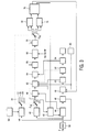
Now further to Fig. 3. In Fig. 3 the histogram intensity control circuit comprises
the histogram measurement memory 40, the processor 42 and the look up table 44. The way in
which these components operate is already described in detail above and will not be explained
any further. The output signal of the look up table 44 forms the input signal of a
horizontal/vertical-zoom circuit 46, a contrast circuit 48, a brightness circuit 50, an RGB
amplifier 52 and a CRT γ-correction circuit 54. All these circuits can be found in prior art
television receivers and do not require any further explanation.
The luminance signal Y is supplied through an AGC-circuit 56 to both the
histogram of measurement memory 40 as well as to the lookup table memory 44. The output
of the histogram memory 40 is connected to a switch S 10 (corresponding to S1 in Fig. 1).
Switch S10 is coupled to a further five-position switch S12 and both switches are in tandem
controlled by a window generator 58 that is controlled by a scene change detector 59. If the
circuit needs data belonging to the left doming area window 32, the right doming area window
34, the left overscan window 33, or the right overscan window 35, then the window generator
58 takes care that the switches S10 and S12 are brought into the corresponding position. If
none of these data is necessary then the switches are brought to the most lower position in
which the circuits 40, 42 and 44 are together functioning as described in the prior art
publication.
If we assume that S10, S12 is in one of its four uppermost positions, then the
output signal of histogram memory 40 is first of all supplied to a histogram correction circuit
60. In fact the circuit 60 emulates the dynamic contrast function which is performed in circuit
44. Thereafter the corrected signal is supplied to a circuit 62 where contrast and brightness
correction are performed based on signals received from the contrast control circuit 48 and the
brightness control circuit 50. A further signal supplied to the circuit 62 is derived from a beam
current limiter 63. As such the beam current limiter 63 is a circuit known from the prior art.
The beam current limiter 63 takes care that under no circumstances the beam current reaches a
higher level than a predetermined limit level. If necessary, the value at the input of circuit 62 is
corrected in case the beam current limiter 63 provides an indication therefore.
The RGB-amplifier 52 has of course its influence on the actual luminance
signal but in the emulation circuit this influence is in fact a constant factor so that no
connection between the RGB amplifier 52 and the correction circuit 62 is necessary.
The influence of the CRT γ-correction circuit 54 is translated into the circuit 64 emulating the
γ -correction.
The values at the output of the γ-correction circuit 64 are sent in a summing
circuit 66 which at the output in fact supplies an estimation of the total beam current of the
measured window:
beam current = γ weight (bucket) x histogram (bucket)
wherein weight (n) is the beam current of each pixel in the bucket number n and histogram (n)
is the amount of pixels of the picture that fall inside it.
The beam current calculated so far depends on the window size because the
total amount of pixels measured by the histogram changes linearly with the window size.
Since the window changes due to 50Hz/60Hz reception conditions a correction has to be
added for which a window size compensation circuit 68 is added.
The prediction calculated so far tends to underestimate the doming effect of the
beam current in cases where one part of the window is light and another is dark. As an
example take a scene with a light sky on the top 25% of the screen and a dark landscape on the
rest. The average beam current of a window will not be high, being dominated by the large
dark area. Still the danger of local doming is large in the sky part. To compensate for this a
black/white balance correction circuit 70 is added where a correction is performed based on
the light/dark distribution.
Depending on the selected window the output signal of the black/white balance
correction circuit 70 is supplied through switch S12 further to either the left part prediction
circuit 72 or to the right part pre-diction circuit 74. These prediction circuits control the
calculate correction circuit 76 which supplies the ultimate correction value to the histogram
algorithm processor 42.
Instead of to the histogram algorithm processor 42 the correction signal could
also be transferred back to the contrast controller 48 as indicated in Fig. 3.
It should be noted that the above-mentioned embodiments illustrate rather than
limit the invention, and that those skilled in the art will be able to design many alternative
embodiments without departing from the scope of the appended claims. In the claims, any
reference signs placed between parentheses shall not be construed as limiting the claim. The
word "comprising" does not exclude the presence of elements or steps other than those listed
in a claim. The word "a" or "an" preceding an element does not exclude the presence of a
plurality of such elements. The invention can be implemented by means of hardware
comprising several distinct elements, and by means of a suitably programmed computer. In the
device claim enumerating several means, several of these means can be embodied by one and
the same item of hardware. The mere fact that certain measures are recited in mutually
different dependent claims does not indicate that a combination of these measures cannot be
used to advantage.
Claims (11)
- A method of preventing doming phenomena, the method comprising the steps of:obtaining (10; 40) luminance histogram distribution values from a luminance signal;processing and normalizing (12; 42) the various luminance histogram distribution values;processing (16; 62) the luminance histogram distribution values to correct for at least the actual contrast and brightness settings to obtain corrected histogram data;predicting (18; 66) the total beam current from said corrected histogram data; andderiving (20; 76) a correction signal from the predicted total beam current and making said correction signal effective in said processing and normalizing step (12; 42).
- A circuit for preventing doming phenomena, the circuit comprising:a histogram memory (10; 40) for obtaining a luminance distribution from a luminance signal;a look up table operating circuit (12; 42) for processing and normalizing the various values in said histogram memory (10; 40);means (16; 62) for processing the histogram data to correct for at least the actual contrast and brightness settings to obtain corrected data;means (18; 66) for predicting the total beam current from said corrected data; andmeans (20; 76) for deriving a correction signal from the predicted total beam current and making said correction signal effective in said look up table operating circuit (12).
- A circuit according to claim 2, wherein only the luminance signals corresponding to predetermined areas (33, 32, 34, 35) on the screen are taken into account.
- A circuit according to claim 3, wherein the predetermined areas (32, 34) cover elongated windows with relatively small horizontal dimension and relatively large vertical dimension at a predetermined distance from the right or left edge respectively of the screen.
- A circuit according to claim 3, wherein the predetermined areas (33, 35) cover elongated windows with relatively small horizontal dimension and relatively large vertical dimension adjacent to the extreme right or left edge respectively of the screen.
- A circuit according to claim 2, wherein a switch (S1; S10) is installed between the histogram memory (10; 40) and the histogram data processing means (16; 66) to connect the output of the histogram memory (10; 40) either with said histogram data processing means (16; 66) or with said look up table operating circuit (12; 42).
- A circuit according to claim 2, wherein said histogram data processing means (16; 66) comprise means for correcting the data in agreement with intensity variations instructed by a look up table memory (14; 44) that stores the processed and normalized histogram values.
- A circuit according to claim 2, wherein the means (18; 66) for predicting the total beam current comprise a summing circuit in which the values, received from the histogram memory (10; 40), after multiplication with a weight factor, are summed to obtain a weighted sum.
- A circuit according to claim 8, wherein the weighted sum is processed in a window size compensation circuit (68) providing compensation for 50Hz/60Hz receiver circuits.
- A circuit according to claim 8, wherein the weighted sum is further processed in a black/white compensation circuit (70) providing compensation for relatively large white surfaces within a window.
- A television receiver comprising a cathode ray tube on the screen of which a picture is produced by means of an electron beam under control of an electronic receiver circuit having intensity, contrast and brightness control means, said intensity control circuit being equipped with a local doming prevention circuit as claimed in claim 2.
Priority Applications (9)
| Application Number | Priority Date | Filing Date | Title |
|---|---|---|---|
| EP00202057A EP1164784A1 (en) | 2000-06-13 | 2000-06-13 | Preventing doming phenomena |
| AT01984024T ATE281040T1 (en) | 2000-06-13 | 2001-05-15 | PREVENTING DOME FORMATION PHENOMENA |
| DE60106761T DE60106761T2 (en) | 2000-06-13 | 2001-05-15 | PREVENT COUPLING PHENOMENONES |
| CNB018017223A CN1197349C (en) | 2000-06-13 | 2001-05-15 | Method and apparatus for preventing doming |
| KR1020027001856A KR20020029100A (en) | 2000-06-13 | 2001-05-15 | Preventing doming phenomena |
| EP01984024A EP1295468B1 (en) | 2000-06-13 | 2001-05-15 | Preventing doming phenomena |
| PCT/EP2001/005574 WO2001097508A1 (en) | 2000-06-13 | 2001-05-15 | Preventing doming phenomena |
| JP2002511101A JP2004503959A (en) | 2000-06-13 | 2001-05-15 | Prevent the doming phenomenon |
| US09/878,682 US6741295B2 (en) | 2000-06-13 | 2001-06-11 | Preventing doming phenomena |
Applications Claiming Priority (1)
| Application Number | Priority Date | Filing Date | Title |
|---|---|---|---|
| EP00202057A EP1164784A1 (en) | 2000-06-13 | 2000-06-13 | Preventing doming phenomena |
Publications (1)
| Publication Number | Publication Date |
|---|---|
| EP1164784A1 true EP1164784A1 (en) | 2001-12-19 |
Family
ID=8171624
Family Applications (2)
| Application Number | Title | Priority Date | Filing Date |
|---|---|---|---|
| EP00202057A Withdrawn EP1164784A1 (en) | 2000-06-13 | 2000-06-13 | Preventing doming phenomena |
| EP01984024A Expired - Lifetime EP1295468B1 (en) | 2000-06-13 | 2001-05-15 | Preventing doming phenomena |
Family Applications After (1)
| Application Number | Title | Priority Date | Filing Date |
|---|---|---|---|
| EP01984024A Expired - Lifetime EP1295468B1 (en) | 2000-06-13 | 2001-05-15 | Preventing doming phenomena |
Country Status (8)
| Country | Link |
|---|---|
| US (1) | US6741295B2 (en) |
| EP (2) | EP1164784A1 (en) |
| JP (1) | JP2004503959A (en) |
| KR (1) | KR20020029100A (en) |
| CN (1) | CN1197349C (en) |
| AT (1) | ATE281040T1 (en) |
| DE (1) | DE60106761T2 (en) |
| WO (1) | WO2001097508A1 (en) |
Families Citing this family (11)
| Publication number | Priority date | Publication date | Assignee | Title |
|---|---|---|---|---|
| KR100393219B1 (en) * | 2001-03-13 | 2003-07-31 | 삼성전자주식회사 | Automatic beam limiter circuit |
| JP3874658B2 (en) * | 2001-12-12 | 2007-01-31 | 三星エスディアイ株式会社 | Contrast correction circuit |
| JP2004032551A (en) * | 2002-06-27 | 2004-01-29 | Seiko Epson Corp | Image processing method, image processing apparatus, and projector |
| JP3844075B2 (en) * | 2003-01-17 | 2006-11-08 | セイコーエプソン株式会社 | Image processing system, projector, program, information storage medium, and image processing method |
| JP3871061B2 (en) * | 2003-03-25 | 2007-01-24 | セイコーエプソン株式会社 | Image processing system, projector, program, information storage medium, and image processing method |
| US8000554B2 (en) * | 2007-04-04 | 2011-08-16 | Xerox Corporation | Automatic dynamic range adjustment in digital imaging |
| TWI390483B (en) * | 2007-04-27 | 2013-03-21 | Realtek Semiconductor Corp | Apparatus and method for contrast control |
| US8537175B1 (en) * | 2009-05-07 | 2013-09-17 | Google Inc. | Video enhancement for large scale applications |
| JP5561524B2 (en) * | 2010-03-19 | 2014-07-30 | ソニー株式会社 | Image processing apparatus and method, and program |
| JP5637383B2 (en) * | 2010-12-15 | 2014-12-10 | ソニー株式会社 | Image processing apparatus, image processing method, and program |
| JP2013041400A (en) * | 2011-08-15 | 2013-02-28 | Sony Corp | Image processing device, image processing method and program |
Citations (4)
| Publication number | Priority date | Publication date | Assignee | Title |
|---|---|---|---|---|
| EP0516083A2 (en) * | 1991-05-28 | 1992-12-02 | Matsushita Electric Industrial Co., Ltd. | Gradation corrector |
| EP0569018A1 (en) * | 1992-05-08 | 1993-11-10 | Matsushita Electric Industrial Co., Ltd. | Gradation correcting apparatus |
| EP0613294A1 (en) * | 1993-02-24 | 1994-08-31 | Matsushita Electric Industrial Co., Ltd. | Gradation correction device and image sensing device therewith |
| EP0772158A2 (en) * | 1995-10-30 | 1997-05-07 | Hewlett-Packard Company | Image processing system |
Family Cites Families (14)
| Publication number | Priority date | Publication date | Assignee | Title |
|---|---|---|---|---|
| FR2406359A1 (en) * | 1977-10-11 | 1979-05-11 | Thomson Csf | IMAGE PROCESSING METHOD AND DEVICE FOR DISPLAY SYSTEM AND DISPLAY SYSTEM INCLUDING SUCH A DEVICE |
| KR0136382B1 (en) * | 1988-08-11 | 1998-04-27 | Sanyo Electric Co | Circuitry for preventing doming phenomenon in a television and the method thereof |
| JPH0785573B2 (en) * | 1988-08-11 | 1995-09-13 | 三洋電機株式会社 | Doming prevention circuit for color television receiver |
| US5289282A (en) * | 1991-05-28 | 1994-02-22 | Matsushita Electric Industrial Co., Ltd. | Video signal gradation corrector |
| JP3019479B2 (en) * | 1991-06-28 | 2000-03-13 | 松下電器産業株式会社 | Gradation correction device |
| JP3016652B2 (en) * | 1992-02-07 | 2000-03-06 | 松下電器産業株式会社 | Gain control circuit |
| FI104521B (en) * | 1997-01-30 | 2000-02-15 | Nokia Multimedia Network Termi | Procedure for improving contrast in image sequences |
| US6373533B1 (en) * | 1997-03-06 | 2002-04-16 | Matsushita Electric Industrial Co., Ltd. | Image quality correction circuit for video signals |
| US6038341A (en) * | 1997-03-06 | 2000-03-14 | Matsushita Electric Industrial Co., Ltd. | Histogram operating unit for video signals |
| JP2951910B2 (en) * | 1997-03-18 | 1999-09-20 | 松下電器産業株式会社 | Gradation correction device and gradation correction method for imaging device |
| JPH10304275A (en) * | 1997-04-25 | 1998-11-13 | Matsushita Electric Ind Co Ltd | Television receiver |
| KR100243301B1 (en) * | 1997-11-24 | 2000-02-01 | 윤종용 | Apparatus and method for expanding dynamic range |
| JP2000125225A (en) * | 1998-10-15 | 2000-04-28 | Matsushita Electric Ind Co Ltd | Brightness correction device |
| US6504954B1 (en) * | 1999-02-05 | 2003-01-07 | Raytheon Company | Closed loop piecewise-linear histogram specification method and apparatus |
-
2000
- 2000-06-13 EP EP00202057A patent/EP1164784A1/en not_active Withdrawn
-
2001
- 2001-05-15 EP EP01984024A patent/EP1295468B1/en not_active Expired - Lifetime
- 2001-05-15 AT AT01984024T patent/ATE281040T1/en not_active IP Right Cessation
- 2001-05-15 KR KR1020027001856A patent/KR20020029100A/en not_active Ceased
- 2001-05-15 WO PCT/EP2001/005574 patent/WO2001097508A1/en not_active Ceased
- 2001-05-15 JP JP2002511101A patent/JP2004503959A/en active Pending
- 2001-05-15 DE DE60106761T patent/DE60106761T2/en not_active Expired - Lifetime
- 2001-05-15 CN CNB018017223A patent/CN1197349C/en not_active Expired - Fee Related
- 2001-06-11 US US09/878,682 patent/US6741295B2/en not_active Expired - Lifetime
Patent Citations (4)
| Publication number | Priority date | Publication date | Assignee | Title |
|---|---|---|---|---|
| EP0516083A2 (en) * | 1991-05-28 | 1992-12-02 | Matsushita Electric Industrial Co., Ltd. | Gradation corrector |
| EP0569018A1 (en) * | 1992-05-08 | 1993-11-10 | Matsushita Electric Industrial Co., Ltd. | Gradation correcting apparatus |
| EP0613294A1 (en) * | 1993-02-24 | 1994-08-31 | Matsushita Electric Industrial Co., Ltd. | Gradation correction device and image sensing device therewith |
| EP0772158A2 (en) * | 1995-10-30 | 1997-05-07 | Hewlett-Packard Company | Image processing system |
Also Published As
| Publication number | Publication date |
|---|---|
| CN1197349C (en) | 2005-04-13 |
| US6741295B2 (en) | 2004-05-25 |
| DE60106761D1 (en) | 2004-12-02 |
| EP1295468B1 (en) | 2004-10-27 |
| EP1295468A1 (en) | 2003-03-26 |
| JP2004503959A (en) | 2004-02-05 |
| KR20020029100A (en) | 2002-04-17 |
| WO2001097508A1 (en) | 2001-12-20 |
| CN1383672A (en) | 2002-12-04 |
| DE60106761T2 (en) | 2005-10-27 |
| ATE281040T1 (en) | 2004-11-15 |
| US20020057388A1 (en) | 2002-05-16 |
Similar Documents
| Publication | Publication Date | Title |
|---|---|---|
| US6373533B1 (en) | Image quality correction circuit for video signals | |
| US5353058A (en) | Automatic exposure control apparatus | |
| US6097848A (en) | Noise reduction apparatus for electronic edge enhancement | |
| JP4372747B2 (en) | Luminance level conversion device, luminance level conversion method, solid-state imaging device, luminance level conversion program, and recording medium | |
| EP1164784A1 (en) | Preventing doming phenomena | |
| EP0459366B1 (en) | Contrast correction device | |
| CA2036100C (en) | Gradation correcting apparatus | |
| JP3208814B2 (en) | Video signal correction device | |
| JP3470906B2 (en) | Television receiver | |
| JP2004007202A (en) | Image processor | |
| US6687300B1 (en) | Motion detection circuit and a noise suppressing circuit including the same | |
| JP2006005699A (en) | Image processing apparatus, image processing program, electronic camera, and image processing method | |
| JPH089197A (en) | Image display device | |
| US5040054A (en) | Circuit apparatus for automatic correction of TV color balance | |
| KR100450193B1 (en) | Contrast compensation circuit | |
| KR100441527B1 (en) | Contrast compensation circuit | |
| JP2003223636A (en) | Image processor | |
| JPH06269015A (en) | Image correction device | |
| JP3997453B2 (en) | Video signal processing device and image display device | |
| JPH02206283A (en) | Gamma correcting device | |
| JPH10294912A (en) | Method and apparatus for extending the dynamic range of an image | |
| JPH06269014A (en) | Picture correction device | |
| US20050220354A1 (en) | Temporal noise reduction and local contrast amplification | |
| JPH06311423A (en) | Automatic exposure controller | |
| JPH10240183A (en) | Shading correction circuit |
Legal Events
| Date | Code | Title | Description |
|---|---|---|---|
| PUAI | Public reference made under article 153(3) epc to a published international application that has entered the european phase |
Free format text: ORIGINAL CODE: 0009012 |
|
| AK | Designated contracting states |
Kind code of ref document: A1 Designated state(s): AT BE CH CY DE DK ES FI FR GB GR IE IT LI LU MC NL PT SE |
|
| AX | Request for extension of the european patent |
Free format text: AL;LT;LV;MK;RO;SI |
|
| STAA | Information on the status of an ep patent application or granted ep patent |
Free format text: STATUS: THE APPLICATION IS DEEMED TO BE WITHDRAWN |
|
| 17P | Request for examination filed |
Effective date: 20020619 |
|
| AKX | Designation fees paid |
Free format text: AT BE CH CY DE DK ES FI FR GB GR IE IT LI LU MC NL PT SE |
|
| 18D | Application deemed to be withdrawn |
Effective date: 20020103 |