EP1164731A2 - Method for protecting a digital communications system - Google Patents
Method for protecting a digital communications system Download PDFInfo
- Publication number
- EP1164731A2 EP1164731A2 EP01304800A EP01304800A EP1164731A2 EP 1164731 A2 EP1164731 A2 EP 1164731A2 EP 01304800 A EP01304800 A EP 01304800A EP 01304800 A EP01304800 A EP 01304800A EP 1164731 A2 EP1164731 A2 EP 1164731A2
- Authority
- EP
- European Patent Office
- Prior art keywords
- unit
- protection
- units
- communications
- fault
- Prior art date
- Legal status (The legal status is an assumption and is not a legal conclusion. Google has not performed a legal analysis and makes no representation as to the accuracy of the status listed.)
- Withdrawn
Links
Images



Classifications
-
- H—ELECTRICITY
- H04—ELECTRIC COMMUNICATION TECHNIQUE
- H04J—MULTIPLEX COMMUNICATION
- H04J3/00—Time-division multiplex systems
- H04J3/02—Details
- H04J3/08—Intermediate station arrangements, e.g. for branching, for tapping-off
-
- H—ELECTRICITY
- H04—ELECTRIC COMMUNICATION TECHNIQUE
- H04J—MULTIPLEX COMMUNICATION
- H04J3/00—Time-division multiplex systems
- H04J3/02—Details
- H04J3/14—Monitoring arrangements
-
- H—ELECTRICITY
- H04—ELECTRIC COMMUNICATION TECHNIQUE
- H04J—MULTIPLEX COMMUNICATION
- H04J2203/00—Aspects of optical multiplex systems other than those covered by H04J14/05 and H04J14/07
- H04J2203/0001—Provisions for broadband connections in integrated services digital network using frames of the Optical Transport Network [OTN] or using synchronous transfer mode [STM], e.g. SONET, SDH
- H04J2203/0057—Operations, administration and maintenance [OAM]
- H04J2203/006—Fault tolerance and recovery
Definitions
- the invention relates to a method for protecting a digital communications system having a number of protection and communications units, and in particular, but not exclusively, a method for protecting a digital communications system employing a 1:N protection scheme.
- Telecommunications systems consist of a number of communications units which are connected to each other and/or to other systems by way of various network arrangements.
- a much simplified representation of a typical communications system is illustrated in Figure 1.
- an SDH digital communications network 10 is connected to a number of communications units 12, 14, 16, 18 by way of a local area network (LAN) 20.
- the various units which in turn are connected either to users ("hosts") or to other networks, are arranged in either a ring configuration 22 or along a bus 24 and one of the units 12, 16 in each case acts as a gateway device interfacing the other units to the LAN 20.
- the ring 22 comprises - purely as an example - STM-16 type units
- the bus 24 comprises STM-4 type units. Many other types of unit are possible, as would be appreciated by one skilled in the art.
- the communications system will provide for certain units to be selected in order to allow communication traffic to flow between one user and another. Such selection is part of a routeing process.
- the various units which may also be termed "ports”, will be configured or reconfigured very frequently during service.
- One known way of providing protection against the failure of a unit is to provide one or more so-called protection units to take over the place of the failed unit.
- N units 20 which correspond for example to the STM units shown in Figure 1 and are commonly termed “worker” units, are under the control of a controller unit 22, which initially configures the units independently in terms of traffic-related port parameters - these parameters including frame structure, signal labelling, path trace, performance monitoring, alarm-consequent actions, signal-degrade thresholds, etc - and, when conditions change (e.g. a new port is configured, or some parameter is changed), updates the configuration data of the relevant units by way of a control bus 24.
- an extra unit 26 is provided - a so-called “protection" unit - which is also under the control of the controller unit 22.
- This additional unit which in a ring environment such as the ring 22 in Figure 1 may take the form of an MS-SPRING (Multiple-Section Shared Protection Ring) device and in a bus environment such as the bus 24 in Figure 1 may be an MSP (Multiple-Section Protection) device, will take over from one of the other units 20, should it fail in service, though it may also be responsible for handling its own traffic during normal operation of the system. If the protection unit has its own traffic, it will normally be low-priority traffic which can tolerate the delay involved in being passed on to another unit or can even afford to be discarded, should a fault arise in a unit 20.
- the illustrated scheme is a so-called "1:N" scheme in which a sole protection unit serves N communication units.
- the conventional way of handing over traffic to the protection unit when a worker unit - e.g. unit 1 - develops a fault is to reconfigure, through the controller unit, the protection unit with the configuration data of unit 1 existing at the moment of fault.
- the fault incidentally, may be an event such as a hardware problem in the unit itself, a protocol command (e.g. a "manual switch to protection” command, a "forced switch to protection” command, a "lockout protection” command or a "clear” command) or a failure indication generated by a sensor, etc.).
- the controller unit in practice performs a complete reconfiguration of the protection unit, copying onto it via the bus 24 the configuration data of unit 1.
- the time the controller unit takes to do this should be as short as possible, so that normal service can be resumed without noticeable degradation.
- This reconfiguration process takes the same time that the initial configuration of unit 1 took, which can be of the order of 50 ms using MSP or MS-SPRING devices for the protection unit.
- the main limitations are the power of the processor (not shown) in the controller unit, the bandwidth of the control bus 14, the efficiency of the protocol used over the control bus and the power of the processor in the protection unit 16.
- a method for effecting protection of a digital communications system involving a K:N protection scheme, as defined in Claim 1.
- the invention provides a K:N protection arrangement for a digital telecommunications system, as defined in Claim 14. Specific realisations of the invention are contained in the subclaims.
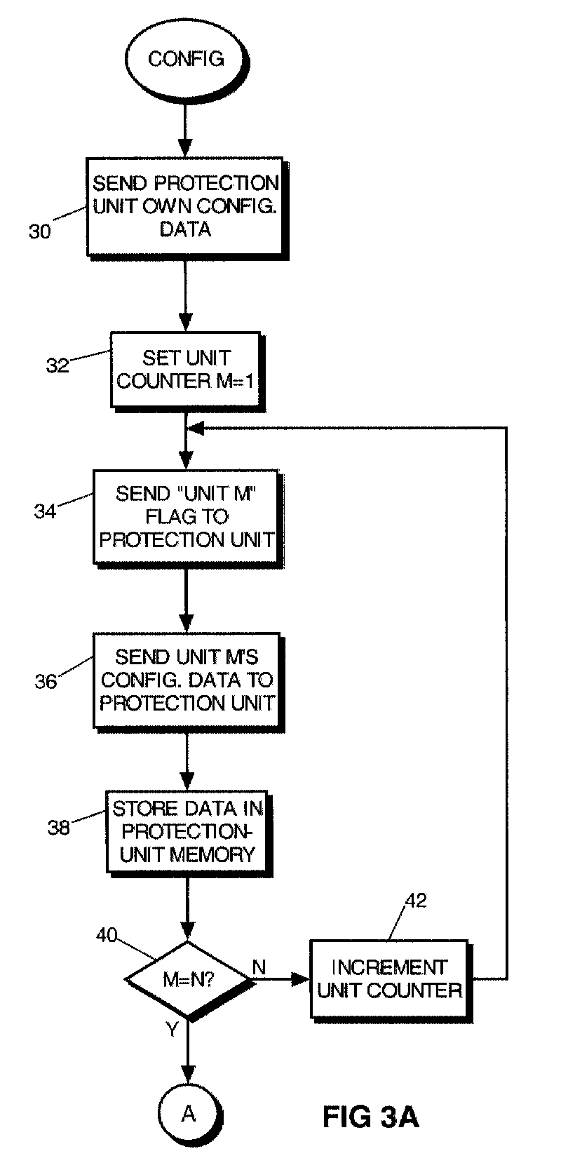
- the protection unit in the communications system is subject to a configuration process shown in Figures 3A and 3B.
- the controller unit 22 issues via the bus 24 the configuration data pertaining to the protection unit itself. Those data may include routeing data, quality-of-service data and frame structure data. This is shown as block 30 in Figure 3A.
- the protection unit is provided with the configuration data relating to the various non-protection units in the communications system, namely units 1 to N.
- this is achieved by, firstly, setting a unit counter value M to 1 in block 32, sending to the protection unit in block 34 a flag indicative of the current value of M (one), then sending to the protection unit the configuration data for that same unit (block 36). These acts are carried out by the controller unit 22 over the bus 24. Finally, these data are stored in a protection-unit memory location dedicated to unit 1 (see block 38). The value of M is then (block 40) compared to the value N, which is the total number of communication units to be associated with the protection unit, and if the two values are not the same, the unit counter is incremented by one (block 42) and the operations of blocks 34 to 40 repeated until the configuration data for all the communication units is resident in respective memory locations in the protection unit. Thus the flags signal to the protection unit that it is to expect the configuration data for a particular worker unit, which the protection subsequently receives and stores away.
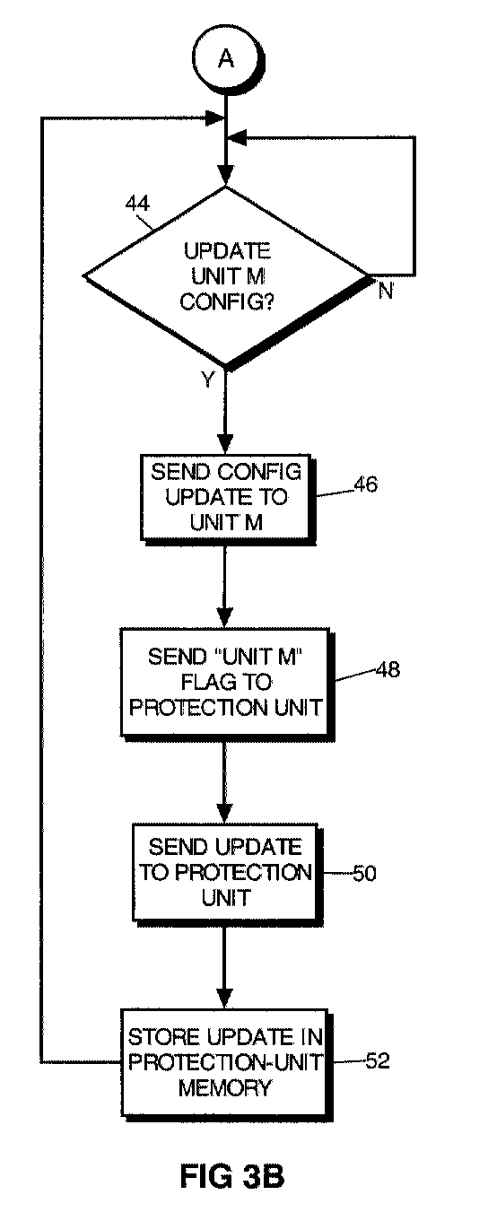
- the controller unit 22 is arranged to monitor the communications system for an indication that the configuration data for any one of the communication "worker" units 20 are to be updated. This will be required if there is a change in routeing or in quality of service, etc.
- This monitoring process is illustrated in block 44.
- the particular update data are sent to the worker unit concerned (unit M, in general terms) (46) and a simple flag is sent to the protection unit (48) to alert it that the data of the relevant worker unit are about to change.
- the controller unit then sends to the protection unit in block 50 the relevant update data, which will normally be in the form of single commands, whereupon the protection unit stores the data in the relevant memory location for that worker unit (block 52).
- the update will normally, in practice, be a replacing of the existing data portion by the new data portion.
- This process is repeated as often as required by the incoming update instructions.
- the issuing of a flag by the control unit simply ensures that the update data are directed into the correct memory area of the protection unit so that the correct configuration data are updated in that unit.
- the data could be sent in any order (e.g. unit 1 followed by unit N followed by unit 2, etc), but it will generally be easier to arrange for the data to be sent in the strict consecutive sequence: unit 1, unit 2,...unit N or the reverse.
- the controller unit which monitors the occurrence of a fault and sends the appropriate flag to the protection unit. While this is a possibility, it might equally be the faulty unit itself which sends the flag, either by way of the bus 24 or by different communication facilities available inside the equipment. Alternatively, depending on the nature of the fault, flagging may be carried out by a sensor which registers the appearance of a fault. It is significant here that, since all that is required is an indication of which unit is affected by the fault, the unit sending that indication does not have to be one which has an overall view of the communication system's configuration (e.g. the controller unit). This means that the flag can be sent more directly under some circumstances, with the result that protection switching can take place faster.
- Speed of switching is, of course, also affected more fundamentally by the fact that only a single flag indication has to be sent to the protection unit in order to trigger the switching. Since the length of the flag is much shorter than the length of the full re-configuration data for any particular worker unit (the flag may be only a few bytes in size), response time will necessarily be shorter than in the prior-art protection method. In addition, switching time is now affected only by the power of the processor in the protection unit, not also by the power of the processor in the controller unit, as would be the case in the prior-art arrangement.
- the amount of power needed to manage the loading of the re-configuration data from the faulty unit's memory location in the protection unit into the traffic-configuration area of the protection unit is less than the power needed to get messages from the control bus, translate them and finally apply them within the protection unit.
- a potential problem which might arise in a practical realisation of the invention is the risk that a flag might be sent to the protection unit at the very time it is being configured with the configuration data of its associated worker units. This could occur, for example, where the unit has previously been taken out of service for some reason (e.g. for repair) and has just been put back into service. In that event it is conceivable that, although it has received the flag, it is not yet ready to act on it, since it could not assume the new configuration relating to the faulty unit. In practice, care is taken that the firmware in the protection unit does not try to perform protection switching in these circumstances before the software has updated the protection unit's traffic-configuration settings to the faulty unit's settings. This firmware inhibition may be effected by the use of appropriate messages, such as "StartConfiguration" and "EndConfiguration" messages.
- each of the K protection units is loaded with the full configuration data of the N worker units with which it is associated and, under a priority scheme, one of the K protection units is sent the flag relating to the first faulty worker unit so that it can take over the traffic of that unit. Subsequent faults are handled in the same way by the rest of the K protection units.
Landscapes
- Engineering & Computer Science (AREA)
- Computer Networks & Wireless Communication (AREA)
- Signal Processing (AREA)
- Maintenance And Management Of Digital Transmission (AREA)
- Data Exchanges In Wide-Area Networks (AREA)
- Small-Scale Networks (AREA)
- Time-Division Multiplex Systems (AREA)
- Detection And Prevention Of Errors In Transmission (AREA)
- Emergency Protection Circuit Devices (AREA)
- Communication Control (AREA)
Abstract
Description
Claims (16)
- A method for effecting protection of a digital communications system having N independently configurable communications units (20) and K protection units (26) allocated to the N communications units, where 1 is less than or equal to K is less than or equal to N, the method comprising the steps of:(a) in an initial setting-up stage for the protection units, supplying each of one or more of the protection units (26) with configuration data relating to the communications units (20) and storing said data in respective memory locations in the each protection unit;(b) where so required, subsequently updating said data with update data relating to said communications units (20);(c) in the event of a fault occurring involving one of the communications units, sending to one of the one or more of the protection units (26) an indication of which communications unit is involved in the fault, and(d) causing that protection unit (26) to use said indication to identify the memory location associated with the fault-related communications unit and to use the configuration data in that memory location as its own configuration data, thereby to take over the role of that communications unit in the communications system.
- Method as claimed in Claim 1, wherein said one or more of the protection units are low-priority-traffic carrying units and are supplied with their own configuration data.
- Method as claimed in Claim 1 or Claim 2, wherein an identification flag is sent to the one or more of the protection units before the configuration-update data relating to the communications units are sent, in order to identify the particular communications unit to which the update data pertain.
- Method as claimed in any one of the preceding claims, wherein said indication is sent to the protection unit by way of a controller unit which controls the configuring of the communications units.
- Method as claimed in Claim 4, wherein said indication is sent to the protection unit from the controller unit by way of a bus.
- Method as claimed in any one of Claims 1 to 3, wherein said indication is sent to the protection unit directly by the fault-related communications unit.
- Method as claimed in any one of Claims 1 to 3, wherein the fault is detected by a sensor device and said indication is sent to the protection unit directly by the sensor device.
- Method as claimed in any one of the preceding claims, wherein the configuration data associated with the communications units 1 to N are supplied to the one or more of the protection units in consecutive sequence from one of communications units 1 and N to the other of communications units 1 and N.
- Method as claimed in any one of Claims 2 to 8, wherein, before the protection unit takes over the role of the fault-related communications unit in the communications system, the traffic previously associated with the protection unit is either diverted to a working communications unit or is discarded.
- Method as claimed in Claim 9, wherein, after the protection unit has taken over the traffic of the fault-related communications unit, the fault which occasioned such taking over is rectified, the taken-over traffic is redirected back to the fault-related unit, the protection unit is provided with its own configuration data and traffic is again supplied to the protection unit.
- Method as claimed in Claim 10, wherein, once the fault has been rectified, the fault-related communications unit is reconfigured with the configuration data currently required of that unit and these configuration data are sent to the one or more of the protection units.
- Method as claimed in any one of the preceding claims, wherein K=1.
- A K:N protection arrangement for a digital telecommunications system having N independently configurable communications (20) and K protection units (26) allocated to the N communications units (20), where 1 is less than or equal to K is less than or equal to N, wherein the arrangement comprises:(a) a means for supplying one or more of the protection units (26) with configuration data relating to the communications units (20) and storing said data in said one or more of the protection units;(b) a means for subsequently updating said data with update data relating to said communications units (20);(c) a means for sensing the occurrence of a fault involving one of the communications units (20);(d) a means for sending to one of the protection units an indication of which communications unit is involved in the fault, and(e) a means for causing the protection unit to use said indication to access the configuration data associated with the fault-related communications unit and to use said configuration data as its own configuration data, thereby to take over the role of that communications unit in the communications system.
- Protection arrangement as claimed in Claim 13, wherein K=1.
- Protection arrangement as claimed in Claim 14, wherein the communications system is an SDH communications system.
- A SDH communications system comprising the protection unit as claimed in any one of Claims 13 to 15
Applications Claiming Priority (2)
| Application Number | Priority Date | Filing Date | Title |
|---|---|---|---|
| ITTO200575 | 2000-06-15 | ||
| IT2000TO000575A IT1320436B1 (en) | 2000-06-15 | 2000-06-15 | PROCEDURE AND CONFIGURATION FOR THE PROTECTION OF A DIGITAL COMMUNICATION SYSTEM. |
Publications (2)
| Publication Number | Publication Date |
|---|---|
| EP1164731A2 true EP1164731A2 (en) | 2001-12-19 |
| EP1164731A3 EP1164731A3 (en) | 2005-09-28 |
Family
ID=11457824
Family Applications (1)
| Application Number | Title | Priority Date | Filing Date |
|---|---|---|---|
| EP01304800A Withdrawn EP1164731A3 (en) | 2000-06-15 | 2001-05-31 | Method for protecting a digital communications system |
Country Status (10)
| Country | Link |
|---|---|
| US (1) | US20020019955A1 (en) |
| EP (1) | EP1164731A3 (en) |
| JP (1) | JP2002101154A (en) |
| CN (1) | CN1181644C (en) |
| AU (1) | AU5192101A (en) |
| HK (1) | HK1042798A1 (en) |
| IT (1) | IT1320436B1 (en) |
| NO (1) | NO20012895L (en) |
| RU (1) | RU2001116710A (en) |
| ZA (1) | ZA200104460B (en) |
Families Citing this family (6)
| Publication number | Priority date | Publication date | Assignee | Title |
|---|---|---|---|---|
| WO2002065306A1 (en) * | 2001-02-12 | 2002-08-22 | Maple Optical Systems, Inc. | System and method for fault notification in a data communication network |
| US7697455B2 (en) * | 2004-02-17 | 2010-04-13 | Dynamic Method Enterprises Limited | Multiple redundancy schemes in an optical network |
| CN1845468B (en) * | 2005-04-07 | 2011-11-30 | 上海贝尔阿尔卡特股份有限公司 | N+1 redundant backup method, processing board and multi processing board system |
| CN101141209B (en) * | 2006-09-04 | 2010-12-08 | 中兴通讯股份有限公司 | A SDH network element data recovery system and method thereof |
| CN100488071C (en) * | 2006-10-27 | 2009-05-13 | 华为技术有限公司 | Method for protecting photoelectric integrated device and photoelectric integrated device |
| CN108494475B (en) * | 2018-03-09 | 2020-01-10 | 苏州大学 | Setting and working method of redundant path in quantum communication network |
Family Cites Families (10)
| Publication number | Priority date | Publication date | Assignee | Title |
|---|---|---|---|---|
| US4141066A (en) * | 1977-09-13 | 1979-02-20 | Honeywell Inc. | Process control system with backup process controller |
| ES2141340T3 (en) * | 1994-03-08 | 2000-03-16 | Excel Switching Corp | IMPROVED REDUNDANCY TELECOMMUNICATION CENTER. |
| US5583796A (en) * | 1995-06-06 | 1996-12-10 | Philips Electronics North America Corporation | Video security backup system |
| JP3432958B2 (en) * | 1995-07-21 | 2003-08-04 | 富士通株式会社 | Optical transmission system and transmission line switching control method |
| US6009075A (en) * | 1996-03-29 | 1999-12-28 | Dsc Communications Corporation | Transport interface for performing protection switching of telecommunications traffic |
| US5793746A (en) * | 1996-04-29 | 1998-08-11 | International Business Machines Corporation | Fault-tolerant multichannel multiplexer ring configuration |
| US6092213A (en) * | 1997-09-30 | 2000-07-18 | Tandem Computers Incorporated | Fault tolerant method of maintaining and distributing configuration information in a distributed processing system |
| US5996086A (en) * | 1997-10-14 | 1999-11-30 | Lsi Logic Corporation | Context-based failover architecture for redundant servers |
| JP2000269999A (en) * | 1999-03-19 | 2000-09-29 | Fujitsu Ltd | Communication device between networks |
| US6578158B1 (en) * | 1999-10-28 | 2003-06-10 | International Business Machines Corporation | Method and apparatus for providing a raid controller having transparent failover and failback |
-
2000
- 2000-06-15 IT IT2000TO000575A patent/IT1320436B1/en active
-
2001
- 2001-05-30 ZA ZA200104460A patent/ZA200104460B/en unknown
- 2001-05-31 EP EP01304800A patent/EP1164731A3/en not_active Withdrawn
- 2001-06-12 US US09/879,864 patent/US20020019955A1/en not_active Abandoned
- 2001-06-12 NO NO20012895A patent/NO20012895L/en not_active Application Discontinuation
- 2001-06-14 AU AU51921/01A patent/AU5192101A/en not_active Abandoned
- 2001-06-14 RU RU2001116710/09A patent/RU2001116710A/en not_active Application Discontinuation
- 2001-06-15 CN CNB011210419A patent/CN1181644C/en not_active Expired - Fee Related
- 2001-06-15 JP JP2001220674A patent/JP2002101154A/en active Pending
-
2002
- 2002-06-13 HK HK02104442.4A patent/HK1042798A1/en unknown
Also Published As
| Publication number | Publication date |
|---|---|
| ZA200104460B (en) | 2001-12-05 |
| CN1181644C (en) | 2004-12-22 |
| NO20012895L (en) | 2001-12-17 |
| ITTO20000575A1 (en) | 2001-12-15 |
| US20020019955A1 (en) | 2002-02-14 |
| EP1164731A3 (en) | 2005-09-28 |
| ITTO20000575A0 (en) | 2000-06-15 |
| AU5192101A (en) | 2001-12-20 |
| IT1320436B1 (en) | 2003-11-26 |
| NO20012895D0 (en) | 2001-06-12 |
| JP2002101154A (en) | 2002-04-05 |
| CN1336745A (en) | 2002-02-20 |
| RU2001116710A (en) | 2003-06-10 |
| HK1042798A1 (en) | 2002-08-23 |
Similar Documents
| Publication | Publication Date | Title |
|---|---|---|
| US10404540B2 (en) | G.8032 misconfiguration detection systems and methods | |
| US7420922B2 (en) | Ring network with variable rate | |
| IL106111A (en) | Group facility protection in a digital telecommunications system | |
| EP0745294A1 (en) | Telecommunications network including a channel switching protection arrangement | |
| JPH07202924A (en) | Communications system | |
| CA2249579A1 (en) | Transport interface for performing protection switching of telecommunications traffic | |
| EP3151491B1 (en) | Protection switching trigger method and apparatus for signal degrade of link aggregation port | |
| US20020019955A1 (en) | Method for protecting a digital communications system | |
| US20030005095A1 (en) | Method and system for programmable submarine network configuration plans to enable diverse service level agreements in telecommunication networks | |
| JP4045419B2 (en) | Transmission path setting method, transmission apparatus and network system | |
| US7287081B1 (en) | Controlled calls in a transmission network | |
| EP2566114B1 (en) | Method and network equipment for dynamically adjusting switching loop | |
| US7013059B2 (en) | Methods for protecting data signals which are being transmitted via optical conductors | |
| CN117135025A (en) | Troubleshooting methods, electronic equipment and media during the lossless bandwidth adjustment process | |
| AU689557B2 (en) | Protection scheme for SDH add/drop multiplexer | |
| JP4045197B2 (en) | Transmission apparatus and concatenation setting method | |
| CA2328035A1 (en) | Method and apparatus for passing control information in a bidirectional line switched ring configuration | |
| US20010038608A1 (en) | Traffic protection mechanism for a fiber optic network having a linear topology | |
| Ellefson | Migration of fault tolerant networks | |
| CN119316344A (en) | A method for alleviating network congestion and related equipment | |
| WO2000043882A1 (en) | Database switching apparatus | |
| JPH09284324A (en) | ATM communication system using loop bus and its switching method | |
| CA2278092A1 (en) | Method and apparatus for routing data traffic away from a failing switchin a communications network | |
| JP2006115387A (en) | Transmission apparatus and transmission apparatus control method | |
| JP2007013289A (en) | NUTTable automatic update system linked with RPR construction |
Legal Events
| Date | Code | Title | Description |
|---|---|---|---|
| PUAI | Public reference made under article 153(3) epc to a published international application that has entered the european phase |
Free format text: ORIGINAL CODE: 0009012 |
|
| AK | Designated contracting states |
Kind code of ref document: A2 Designated state(s): AT BE CH CY DE DK ES FI FR GB GR IE IT LI LU MC NL PT SE TR |
|
| AX | Request for extension of the european patent |
Free format text: AL;LT;LV;MK;RO;SI |
|
| PUAL | Search report despatched |
Free format text: ORIGINAL CODE: 0009013 |
|
| AK | Designated contracting states |
Kind code of ref document: A3 Designated state(s): AT BE CH CY DE DK ES FI FR GB GR IE IT LI LU MC NL PT SE TR |
|
| AX | Request for extension of the european patent |
Extension state: AL LT LV MK RO SI |
|
| AKX | Designation fees paid | ||
| REG | Reference to a national code |
Ref country code: DE Ref legal event code: 8566 |
|
| STAA | Information on the status of an ep patent application or granted ep patent |
Free format text: STATUS: THE APPLICATION IS DEEMED TO BE WITHDRAWN |
|
| 18D | Application deemed to be withdrawn |
Effective date: 20060329 |