EP1164446A2 - Intelligent logic activity resolution - Google Patents
Intelligent logic activity resolution Download PDFInfo
- Publication number
- EP1164446A2 EP1164446A2 EP01108192A EP01108192A EP1164446A2 EP 1164446 A2 EP1164446 A2 EP 1164446A2 EP 01108192 A EP01108192 A EP 01108192A EP 01108192 A EP01108192 A EP 01108192A EP 1164446 A2 EP1164446 A2 EP 1164446A2
- Authority
- EP
- European Patent Office
- Prior art keywords
- conditions
- ilar
- subset
- state
- trigger event
- Prior art date
- Legal status (The legal status is an assumption and is not a legal conclusion. Google has not performed a legal analysis and makes no representation as to the accuracy of the status listed.)
- Granted
Links
Images


Classifications
-
- G—PHYSICS
- G06—COMPUTING OR CALCULATING; COUNTING
- G06F—ELECTRIC DIGITAL DATA PROCESSING
- G06F9/00—Arrangements for program control, e.g. control units
-
- G—PHYSICS
- G05—CONTROLLING; REGULATING
- G05B—CONTROL OR REGULATING SYSTEMS IN GENERAL; FUNCTIONAL ELEMENTS OF SUCH SYSTEMS; MONITORING OR TESTING ARRANGEMENTS FOR SUCH SYSTEMS OR ELEMENTS
- G05B19/00—Program-control systems
- G05B19/02—Program-control systems electric
- G05B19/04—Program control other than numerical control, i.e. in sequence controllers or logic controllers
- G05B19/042—Program control other than numerical control, i.e. in sequence controllers or logic controllers using digital processors
-
- Y—GENERAL TAGGING OF NEW TECHNOLOGICAL DEVELOPMENTS; GENERAL TAGGING OF CROSS-SECTIONAL TECHNOLOGIES SPANNING OVER SEVERAL SECTIONS OF THE IPC; TECHNICAL SUBJECTS COVERED BY FORMER USPC CROSS-REFERENCE ART COLLECTIONS [XRACs] AND DIGESTS
- Y10—TECHNICAL SUBJECTS COVERED BY FORMER USPC
- Y10S—TECHNICAL SUBJECTS COVERED BY FORMER USPC CROSS-REFERENCE ART COLLECTIONS [XRACs] AND DIGESTS
- Y10S706/00—Data processing: artificial intelligence
- Y10S706/902—Application using ai with detail of the ai system
- Y10S706/903—Control
Definitions
- the present invention concerns automated process control and pertains particularly to use of intelligent logic activity resolution within an automated process control system.
- each state can only transition to a limited number of other states based on fixed transition events. For example, a manufacturing process in a first state can only transition to a second state upon the occurrence of a first transition event or into a third state upon the occurrence of a second transition event. All other states and transition events are considered invalid. Under this static state transition process model, if, while in the first state, a third transition event occurs, the model will not be able to determine a next valid state. Instead, the system would, for example, issue an alarm and halt the manufacturing process.
- intelligent logic activity resolution is provided for a process.
- a first trigger event Upon a first trigger event being received, a first subset of conditions of the process is detected. The first subset of conditions is selected based on the first trigger event. When the first subset of conditions match predetermined values, a first state is entered. When the first subset conditions do not match the predetermined values, additional conditions are checked. On the basis of the checked additional conditions, a new state is selected for entry.
- the detection of the first subset of conditions is done by running a separate metaprocedure to detect each condition in the first subset of conditions.
- a metaprocedure is a software function that performs an automated check for a condition.
- a metaprocedure can also perform non-state change related functions such as sending messages to external systems, or storing and retrieving data variables relevant to the process.
- each condition is represented with a single metaprocedure.
- the subset of conditions are also selected based on a current state of the process.
- a second subset of conditions of the process are detected.
- the second subset of conditions are selected based on the second trigger event.
- a corresponding state is entered.
- additional conditions are checked. On the basis of the checked additional conditions a new state is selected for entry.
- the ILAR system described herein removes the constraints of the static connected state transition model.
- the ILAR system disconnects the state and transition event relationship and treats each state and transition event as a unique and independent occurrence.
- the ILAR heuristically determines the next state based on an analysis of all detectable manufacturing process conditions rather than the transition event detected. With this method, all states and transitions are always valid, unless specifically declared invalid by the user. This is a significant advance over prior art state machines.
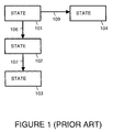
- Figure 1 illustrates operation of a standard state transition model in accordance with the prior art.
- a manufacturing process currently in a state 101 can transition to a state 102 upon the occurrence of a transition event 106.
- the manufacturing process can also transition to a state 104 upon the occurrence of a transition event 109.
- the manufacturing process can transition to a state 103 upon the occurrence of a transition event 107. All other states and transition events are considered invalid.
- this static state transition process model if, while in state 101, transition event 107 occurs, the model will not be able to determine a next valid state. Instead, the system would, for example, issue an alarm and halt the manufacturing process.
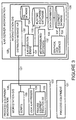
- FIG. 2 illustrates intelligent logic activity resolution (ILAR) in accordance with the preferred embodiment of the present invention.
- the ILAR system described herein removes the constraints of the static connected state transition model.
- An ILAR system disconnects the state and transition event relationship and treats each state and transition event as a unique and independent occurrence.
- the ILAR system heuristically determines the next state based on an analysis of all detectable manufacturing process conditions. This allows significant flexibility over the standard approach of basing state transitions just on a detected transition event.
- an ILAR logic decision engine 110 is made up of one or more independent decision processes that query all possible process conditions to determine a process state.
- the query processes are, for example, linked in Boolean logic trees to allow decisions to be made based upon the process queries.
- all states and transitions are always valid, unless specifically declared invalid by the user that programs the ILAR system. If ILAR logic decision engine 110 detects an event specifically declared invalid, ILAR logic decision engine 110 will behave much like the static state model by issuing an alarm and halting the process. In the case of a transition event that causes a state that is not declared invalid and not previously detected, ILAR logic decision engine 110 will run a user defined set of default metaprocedures known as differentia in order to re-establish the correct process state. Using this method, ILAR logic decision engine 110 can detect and report in real time new manufacturing process conditions.
- a state 111, a state 112 and a state 113 are independent state locations, linked by a dynamically allocated event transition 116, a dynamically allocated event transition 117, a dynamically allocated event transition 118 and a dynamically allocated event transition 119.
- This organization allows ILAR logic decision engine 110 to be easily adaptable and modified to provide real time behavioral determination of process execution.
- ILAR logic decision engine 110 The organization shown in Figure 2 allows transitions and states from different processes to be combined into higher order logic decision engines within ILAR logic decision engine 110. This allows ILAR logic decision engine 110 to be able to monitor and control a larger portion of the process.
- the dynamic nature of the manufacturing process is represented by the dynamic configuration capability of ILAR logic decision engine 110.
- each of the states and transitions can be assigned a time parameter. If the state or transition triggers the time parameter, ILAR logic decision engine 110 can execute without the need for a specific process transition. In this way, the lack of process activity can also be detected and monitored.
- FIG. 3 is a simplified block diagram that shows a specific implementation of an intelligent logic activity resolution (ILAR) system within a manufacturing process.
- ILAR intelligent logic activity resolution
- Process equipment 121 may be, for example, an Agilent 83000 test system available from Agilent Technologies, Inc. Alternatively, process equipment 121 may be a materials handler or any other type of processing equipment manageable by a workstation.
- Process equipment 121 is managed by a process equipment workstation 122.
- a workstation operating system (O/S) 126 runs.
- Workstation operating system 126 is, for example, the UNIX operating system, Windows NT operating system, Linux operating system, or another available operating system.
- the ILAR system uses scripts 125 on the local station to execute required conditional check functions.
- a local ILAR process 124 coordinates execution of scripts 125 in accordance with instructions from an ILAR server workstation 128.
- Local ILAR process 124 also coordinates the transfer of process trigger events to ILAR server workstation 128 via a connection 127.
- Connection 127 is implemented, for example as part of a TCP/IP network.
- Workstation operating system 129 is, for example, the UNIX operating system, Windows NT operating system, Linux operating system, or another available operating system.
- Figure 3 shows that within workstation O/S 129, various software processes run. These software processes along with local ILAR process 124 compose the ILAR system.
- a distributed message hub 130 provides interprocess communication such as the process trigger events from process equipment workstation 126.
- Distributed message hub 130 is implemented, for example, using a Hume Integration Services Distributed Message Hub mailbox server, available from Hume Integration Services, having a business address of 35 Sundown Parkway, Austin, Texas 78746.
- the Hume Distributed Message Hub is a high-level software facility providing interprocess communication for applications executing within a TCP/IP network.
- Any source-connection process (equipment, driver, process, user, etc.) such as local ILAR process 124 or any other source-connection process existing on process equipment workstation 122 or other workstations used to control process equipment, request and present data from a particular external source via mailbox messages in the Hume mailbox (mbx) system within distributed message hub 130.
- mbx Hume mailbox
- An ILAR execution engine 131 makes decisions about the current state of process equipment 121 and potentially other pieces of equipment. ILAR execution engine 131 takes action when the perceived state changes. The actions performed include the updating of the ILAR system's internal representation of the state of the processing equipment and may include the generation of messages to process equipment workstation 122, the requesting of information from a user and/or the display of messages to the user.
- a user utilizes an ILAR graphical user interface 133 to specify within a database 137 process equipment types and process trigger events. From equipment database 136, a data distributor 136 prepares a runtime equipment database 135 utilized by ILAR execution engine 131 during runtime. The user also utilizes graphical user interface 133 to define and save process analysis metaprocedures and process state differentia, as represented in Figure 3 by a block 132.
- the decision logic that the Execution Engine follows is user defined, and also resides in a SQL database 135. The decision logic is composed of logical units and the links between them. ILAR execution engine 131 stores run time process status variables and other run time information in SQL database 134.
- Graphical user interface 133 is JAVA based and uses the Hume Data Hub tool to create and store centralized equipment database 137.
- ILAR execution engine 131 is written in tcl, using the Hume Data Hub mbx and database extensions. Each source-connection process may be written in whatever language is convenient to the communication method of the source and the requirement of writing to the Hume mbx system.
- the total ILAR system takes advantage of the inherent logical structure of a process. As discussed above, a process is made up of the operation of one or more pieces of equipment. Each piece of equipment is defined by its type.
- a process moves through a series of states. For example, one state is loading material. Another state is testing material. A third state is calibration the process system. And so on.
- Each process has one or more identifiable process conditions. For example, one process condition is that an operator is logged into the process system. Another process condition is that a test program is loaded. Another process condition is that a test program is running. Another process condition is that a materials handler is moving material into a chamber for processing. And so on.
- Each state can be identified by a unique set of one or more process conditions. For example, in one set of processing conditions, the state "testing" can be identified when all the following conditions are true: an operator is logged into the process system, a test program is loaded and a test program is running.
- a process trigger event occurs when material is loaded.
- a process trigger event occurs when a test has begun.
- a process trigger event occurs when a test has finished.
- a process trigger event occurs when material has been unloaded. And so on.
- the transition from one state to another is detected by monitoring the process trigger events.
- the user defines five different types of process information.
- the five different types of process information are: (1) equipment types; (2) equipment states; (3) process trigger events; (4) metaprocedures; and, (5) differentia.
- a metaprocedure is a software function that performs an automated check for a condition. Each condition is represented with a single metaprocedure.
- differentia is a defined process condition set that indicates a process state.
- Each differentia represents a unique set of process conditions that define a unique process state.
- ILAR graphical user interface 133
- the user associates the five process information components to define a specific instance of a process execution. ILAR works by implementing the generated process logic.
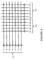
- FIG. 4 illustrates logic relationship between trigger events, metaprocedures and elapsed timers as programmed by a user.
- Seven trigger events 141 are shown: an trigger event T1, an trigger event T2, an trigger event T3, an trigger event T4, an trigger event T5, an trigger event T6 and an trigger event T7.
- Five process condition metaprocedures 142 are shown: a metaprocedure M1, a metaprocedure M2, a metaprocedure M3, a metaprocedure M4 and a metaprocedure M5.
- Five process event elapsed timers 143 are shown: an elapsed timer ET1, an elapsed timer ET2, an elapsed timer ET3, an elapsed timer ET4 and an elapsed timer ET5.
- Table 1 below describes process execution logic for the logic relationships shown in Figure 4.
- the ILAR system can provide a unique process execution logic relationship and table for each state the process can be in.
- Trigger event Run MP Start Timers P.S. on Pass MP fails; Timer Expires T1 M1,M4 ET1,ET5 A Run all MPs Run all MPs T2 M3 ET4 B Run MPs M1,M4,M5 Run all MPs T3 M5 ET2 C Run all MPs Send Trigger T2 T4 M2 ET2 D Run MPs M3,M5 Run all MPs T5 M3,M4 ET3,ET4 E Run all MPs Send Trigger T7 T6 M2,M4 ET1,ET5 F Run MPs M1,M3 Run all MPs T7 M1 ET3 G Run all MPs Run all MPs Run all MPs Run all MPs Run all MPs Run all MPs
- the first column sets out the trigger events.
- the second column shows which metaprocedures (MPs) are run for each trigger event set out in the first column.
- the third column shows which timers are started for each trigger event set out in the first column.
- the fourth column shows which process state (P.S.) is set if the metaprocedures set out in the second column pass when they are run as a result of the trigger event set out in the first column.
- the fifth column shows which metaprocedures are run e.g., all the metaprocedures) when the metaprocedures set out in the second column do not pass when they are run as a result of the trigger event set out in the first column.
- the sixth column shows which metaprocedures are run (i.e., all the metaprocedures) when the timers set out in the third column expire after being started as a result of the trigger event set out in the first column.
- the expiration of a timer can also result in the generation of a new trigger to the input of ILAR execution engine 131.
- FIG. 5 is a flowchart that describes operation of the ILAR system.
- the ILAR system starts up.
- all metaprocedures are run in order to query the process for all possible conditions.
- a metaprocedure is a software function that performs an automated check for a condition. Each condition is represented with a single metaprocedure.
- ILAR execution engine 131 compares the resulting map of conditions that return logical true and logical false results against all of the defined process condition sets. These condition sets are known in the ILAR system as differentia. As discussed above, each differentia represents a unique set of process conditions that define a unique process state. ILAR execution engine 131 returns as a result, the unique process state it has identified.
- a step 154 the ILAR system now waits for a process trigger event.
- the absence of a trigger event over a user determined period of time could itself represent an internally generated trigger event (i.e., the expiration of a timer).
- a step 155 is entered upon the occurrence of a trigger event.
- the ILAR system runs a subset of user defined metaprocedures to determine if the process is in the state that the user would expect based on the previous state and the trigger event.
- a check is made to see if process is in the state that the user would expect based on the previous state and the trigger event (pass). If so, in a step 157, the correct state is set and in step 154, the next trigger event is awaited.
- step 156 the ILAR check fails, i.e., in a step 158 the process is not in the expected state based on the previous state and trigger event, the ILAR begins to run more metaprocedures until it can once again establish a passing differentia and determine the correct state. Then, in step 154, the next trigger event is awaited.
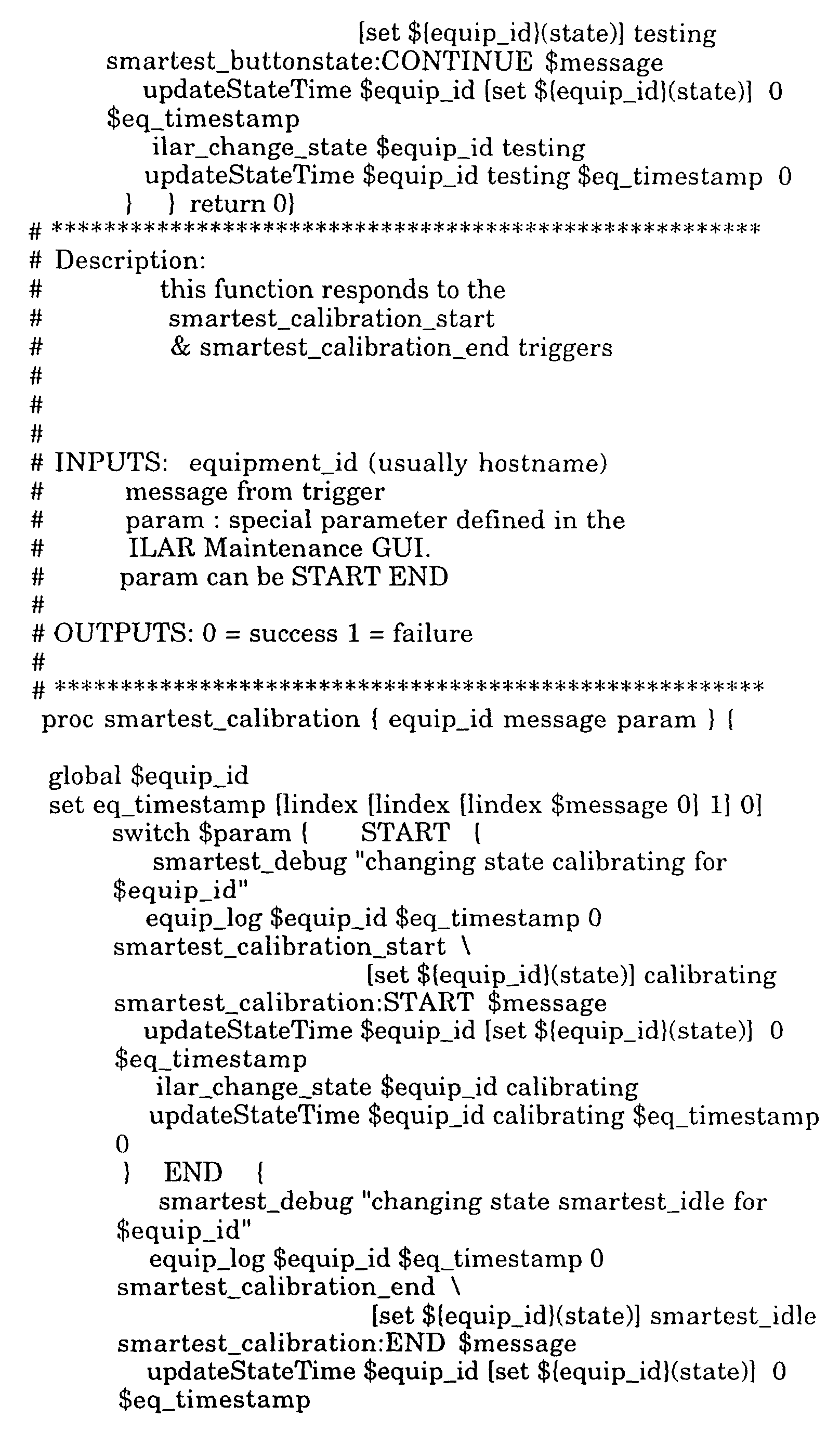
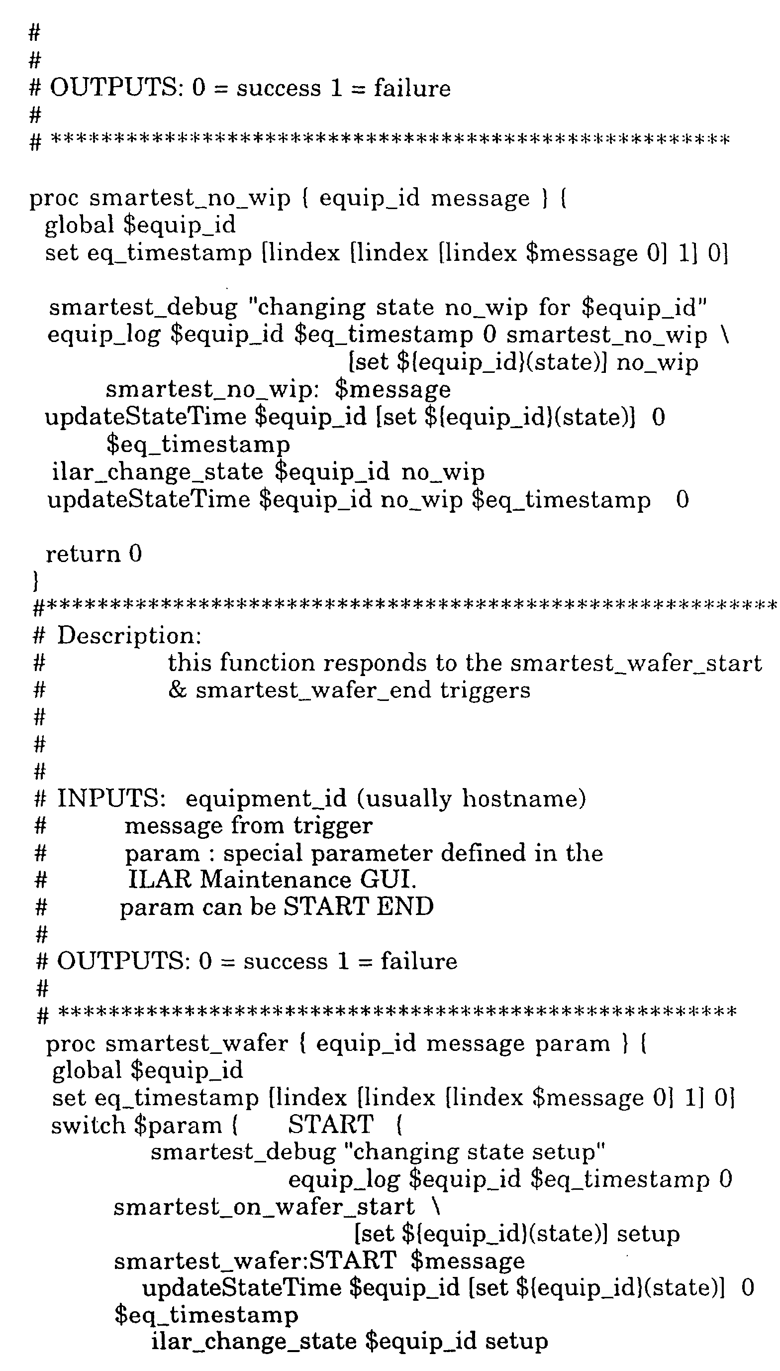
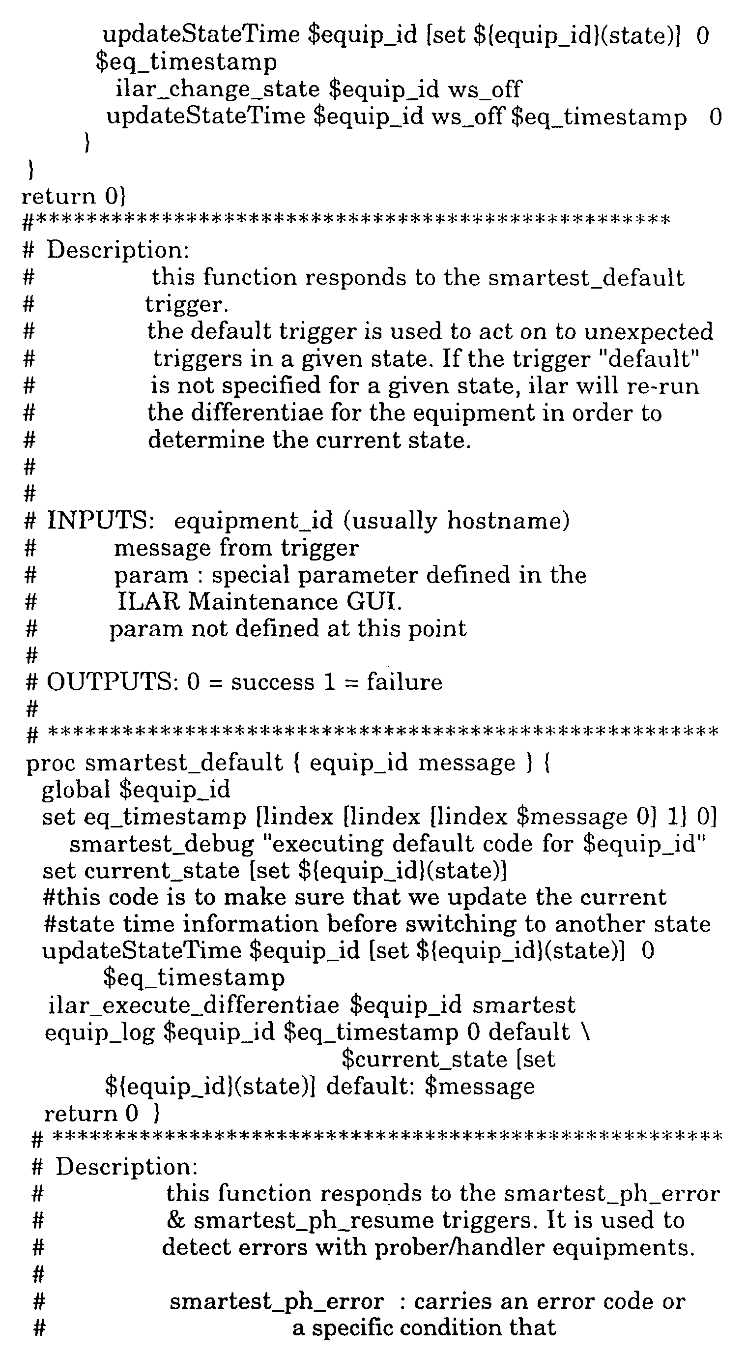
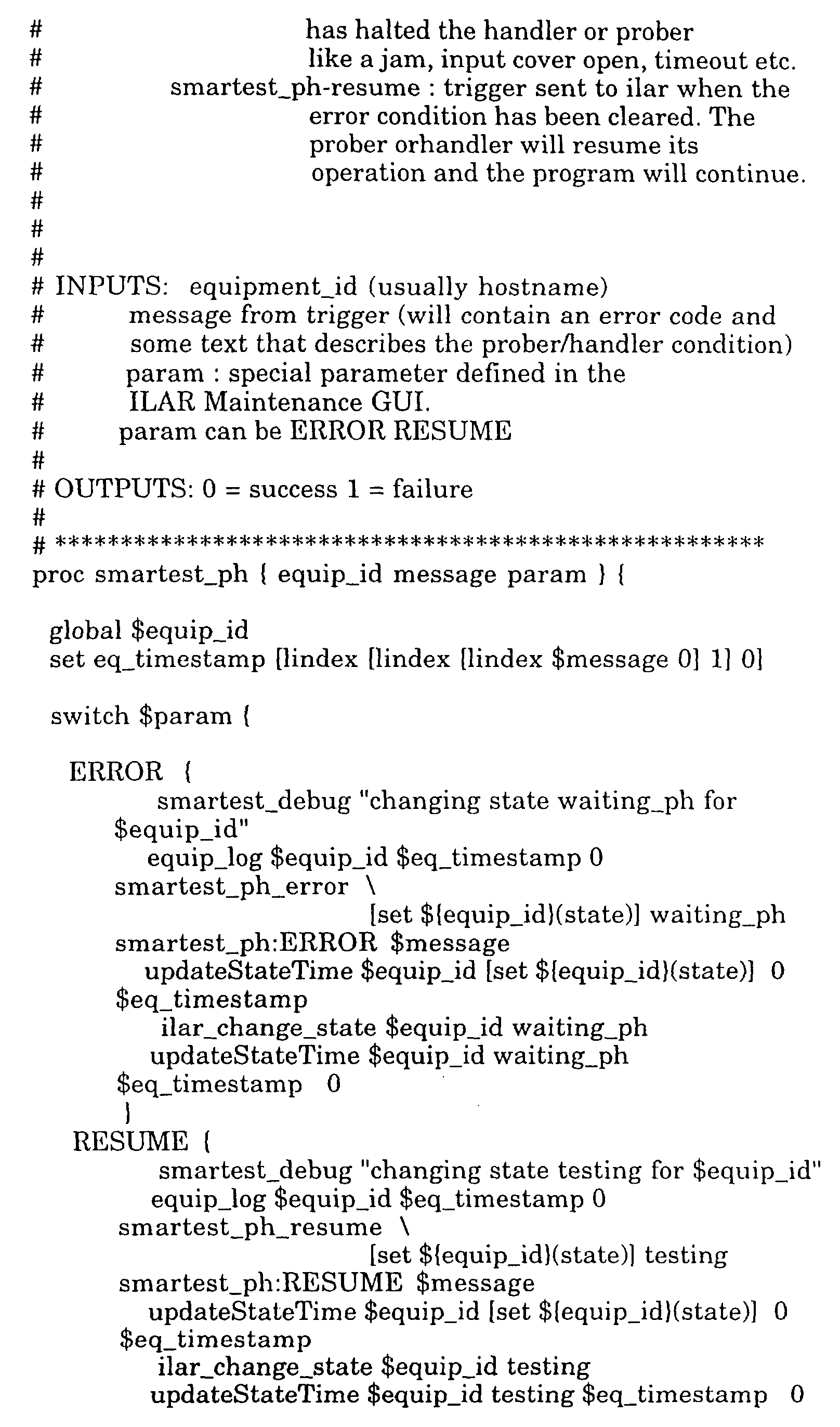
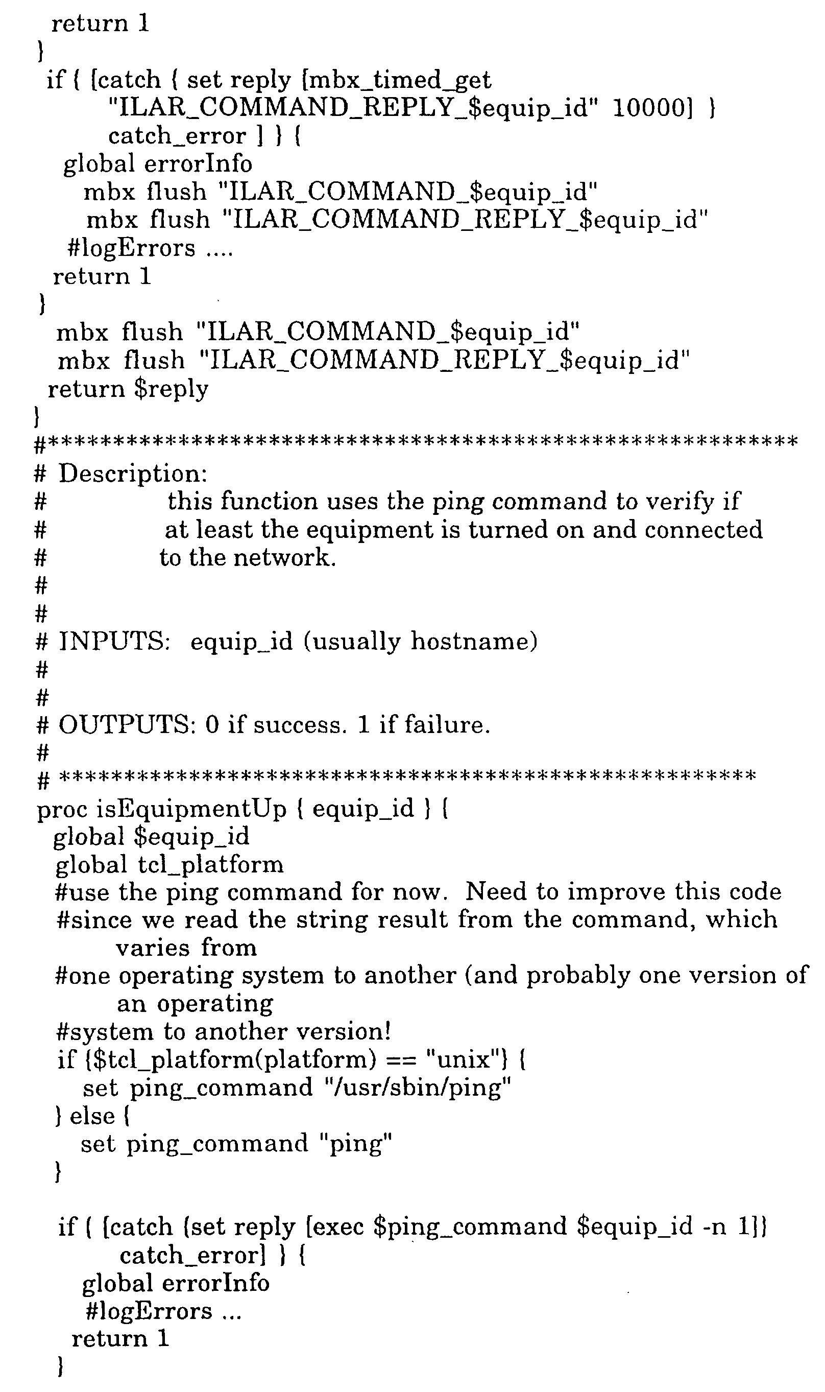
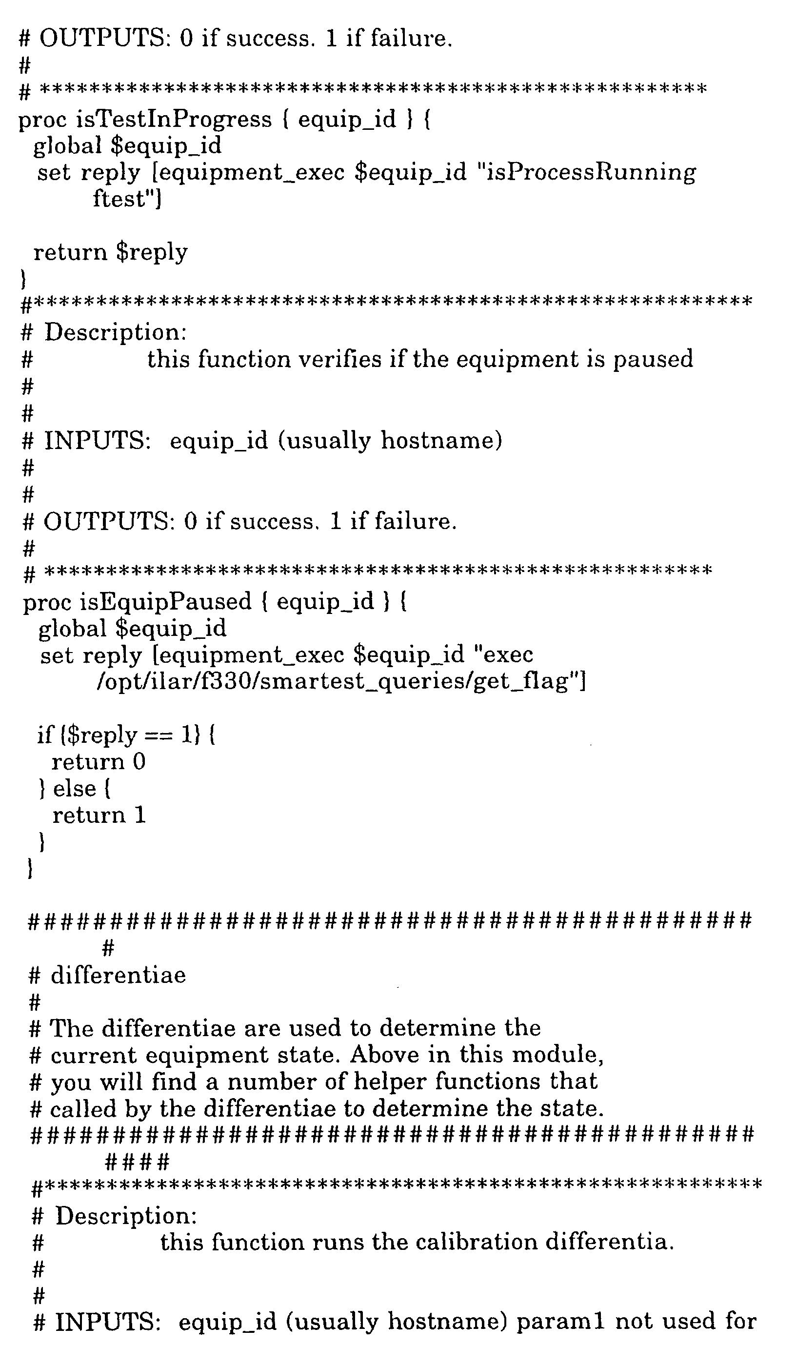
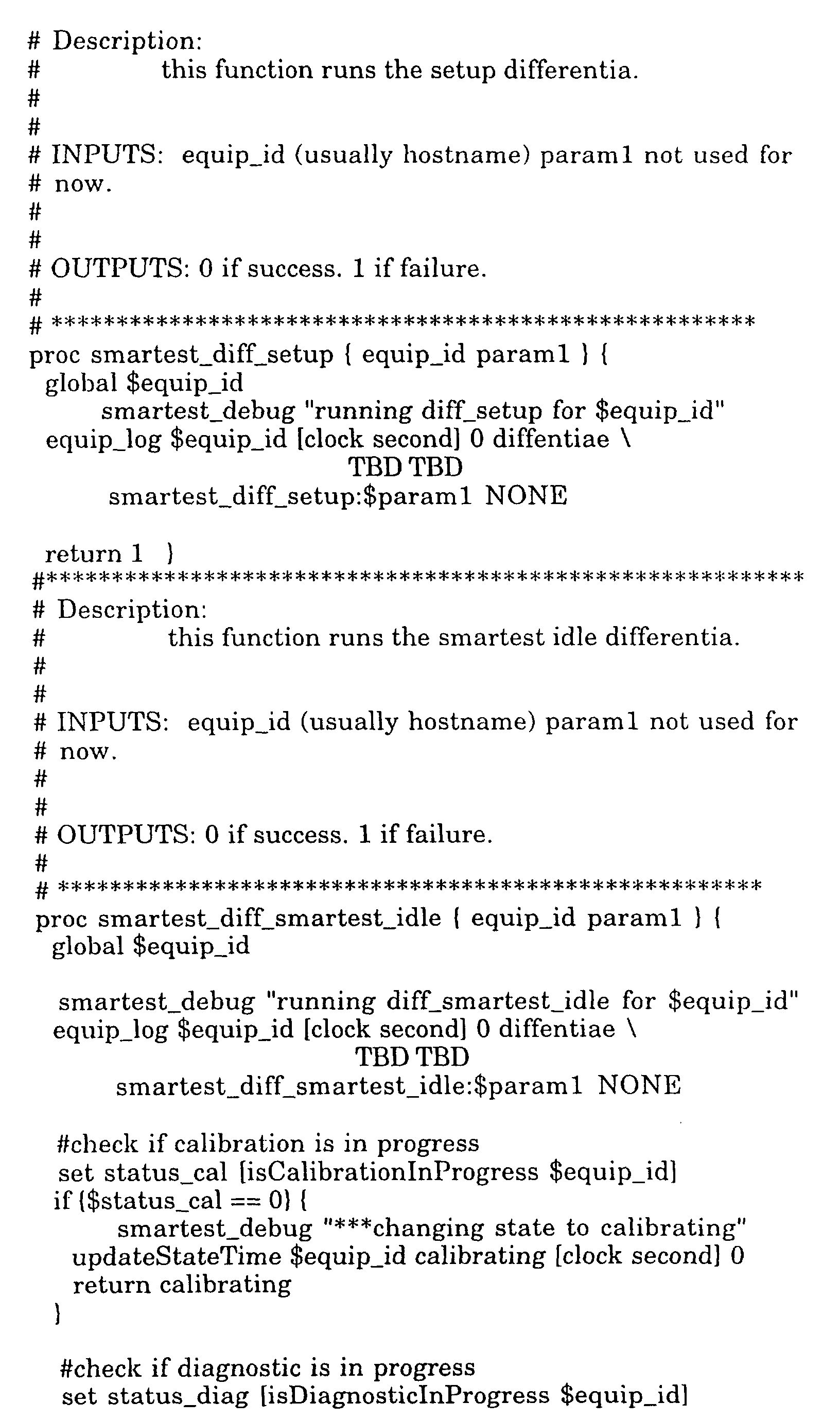
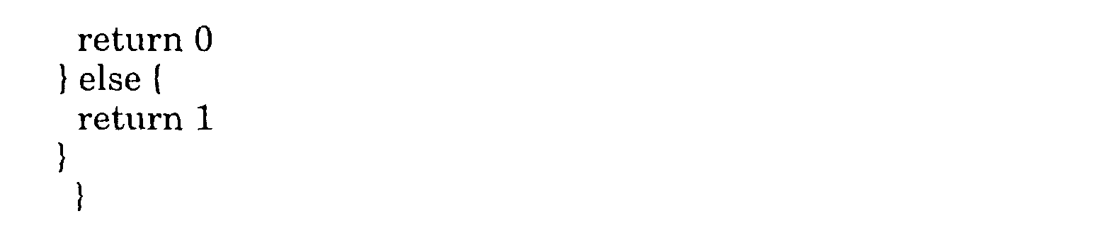
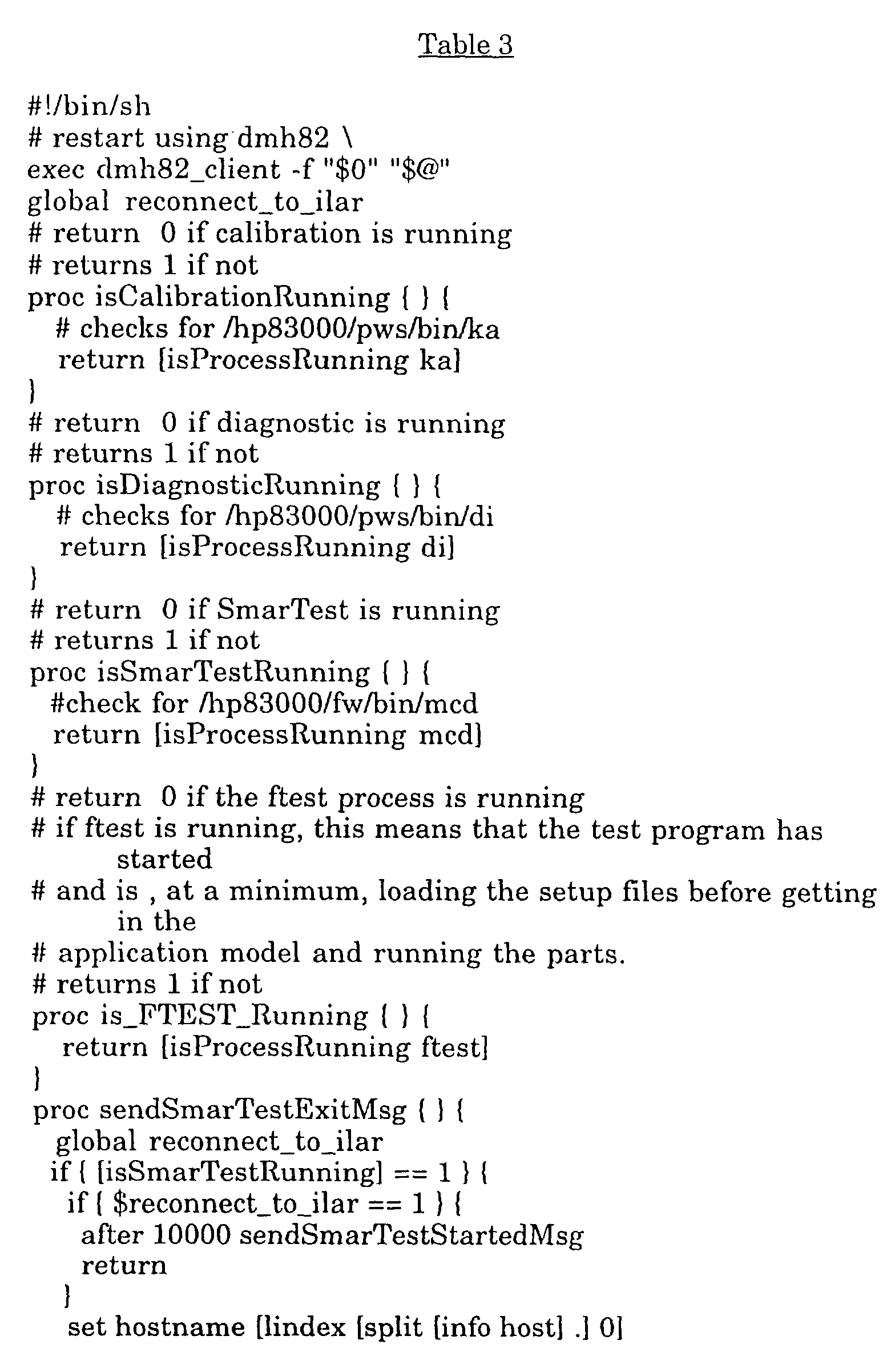
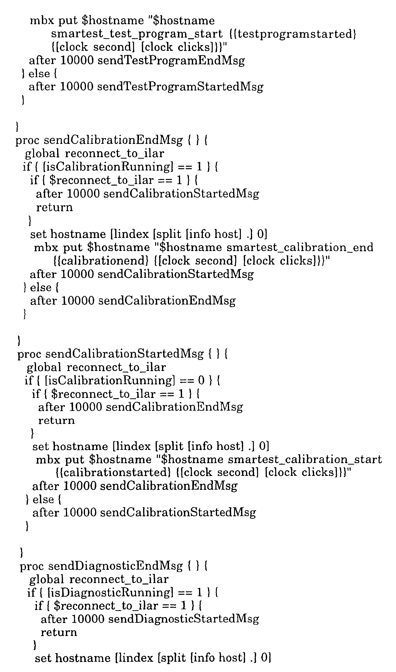
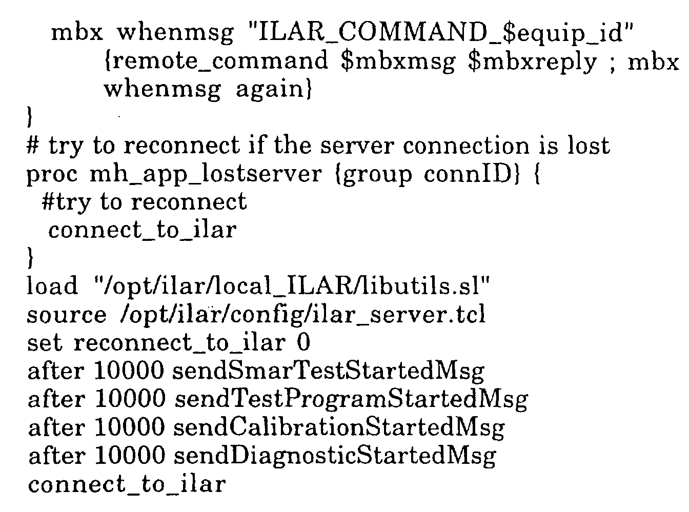
- Table 2 and Table 3 below show two example metaprocedures used in a test installation.
Landscapes
- Engineering & Computer Science (AREA)
- Physics & Mathematics (AREA)
- General Physics & Mathematics (AREA)
- Automation & Control Theory (AREA)
- Theoretical Computer Science (AREA)
- Software Systems (AREA)
- General Engineering & Computer Science (AREA)
- Debugging And Monitoring (AREA)
- Testing And Monitoring For Control Systems (AREA)
- Tests Of Electronic Circuits (AREA)
Abstract
Description
| Trigger event | Run MP | Start Timers | P.S. on Pass | MP fails; | Timer Expires |
| T1 | M1,M4 | ET1,ET5 | A | Run all MPs | Run all MPs |
| T2 | M3 | ET4 | B | Run MPs M1,M4,M5 | Run all MPs |
| T3 | M5 | ET2 | C | Run all MPs | Send Trigger T2 |
| T4 | M2 | ET2 | D | Run MPs M3,M5 | Run all MPs |
| T5 | M3,M4 | ET3,ET4 | E | Run all MPs | Send Trigger T7 |
| T6 | M2,M4 | ET1,ET5 | F | Run MPs M1,M3 | Run all MPs |
| T7 | M1 | ET3 | G | Run all MPs | Run all MPs |
| M1 | M2 | M3 | M4 | M5 | Set State |
| Pass | Pass | A | |||
| Pass | B | ||||
| Pass | C | ||||
| Pass | D | ||||
| Pass | Pass | E | |||
| Pass | Pass | F | |||
| Pass | G |














Claims (10)
- A method for providing intelligent logic activity resolution for a process comprising the following step:(a) performing the following substeps upon receiving a first trigger event (141):(a.1) detecting a first subset of conditions of the process, the first subset of conditions being selected based on the first trigger event (141),(a.2) when the first subset of conditions match predetermined values, entering a first state (111-113); and,(a.3) when the first subset conditions do not match the predetermined values, performing the following substeps:checking additional conditions, andselecting a new state (111-113) to enter on the basis of the checked additional conditions.
- A method as in claim 1 wherein upon start-up performing the following:
checking conditions to select an initial state (111-113) to enter. - A method as in claim 1 wherein in substep (a.1) the detection of the first subset of conditions is done by running a separate metaprocedure (142) to detect each condition in the first subset of conditions.
- A method as in claim 1 additionally comprising the following condition:(b) performing the following substeps upon receiving a second trigger event (141):(b.1) detecting a second subset of conditions of the process, the second subset of conditions being selected based on the second trigger event (141),(b.2) when the second subset of conditions match predetermined values, entering a corresponding state (111-113); and,(b.3) when the second subset of conditions do not match the predetermined values, performing the following substeps:checking additional conditions, andselecting a new state (111-113) to enter on the basis of the checked additional conditions.
- An intelligent logic activity resolution (ILAR) system for a process, the ILAR system comprising:local ILAR (124) for monitoring process equipment to detect trigger events (141);ILAR execution engine (131), the ILAR execution engine (131), upon receiving notification of a first trigger event (141), detects a first subset of conditions of the process, the first subset of conditions being selected based on the first trigger event (141), when the first subset of conditions match predetermined values, the ILAR execution engine (131) enters a first state (111-113), and when the first subset conditions do not match the predetermined values, the ILAR execution engine (131) checks additional conditions, and on the basis of the checked additional conditions selects a new state (111-113) to enter.
- An ILAR system as in claim 5 wherein the ILAR execution engine (131) detects the first subset of conditions is done by running a separate metaprocedure (142) to detect each condition in the first subset of conditions.
- An ILAR system as in claim 5 wherein upon receiving a second trigger event (141) the ILAR execution engine (131) detects a second subset of conditions of the process, the second subset of conditions being selected based on the second trigger event (141), when the second subset of conditions match predetermined values, the ILAR execution engine (131) enters a first state (111-113), and when the second subset of conditions do not match the predetermined values, the ILAR execution engine (131) checks additional conditions and on the basis of the checked additional conditions selects a new state (111-113) to enter.
- An ILAR system as in claim 5 wherein the subset of conditions are also selected based on a current state (111-113) of the process.
- An ILAR system as in claim 5 additionally comprising a graphics user interface (133) that allows a user to specify equipment types, trigger events (141) for the process, metaprocedures (142) and differentia.
- An ILAR system as in claim 5 additionally comprising a distributed message hub (130) that facilitates communication between the ILAR execution engine (131) and the local ILAR (124).
Applications Claiming Priority (2)
| Application Number | Priority Date | Filing Date | Title |
|---|---|---|---|
| US09/594,367 US6665650B1 (en) | 2000-06-15 | 2000-06-15 | Intelligent logic activity resolution |
| US594367 | 2000-06-15 |
Publications (3)
| Publication Number | Publication Date |
|---|---|
| EP1164446A2 true EP1164446A2 (en) | 2001-12-19 |
| EP1164446A3 EP1164446A3 (en) | 2004-04-07 |
| EP1164446B1 EP1164446B1 (en) | 2008-08-13 |
Family
ID=24378583
Family Applications (1)
| Application Number | Title | Priority Date | Filing Date |
|---|---|---|---|
| EP01108192A Expired - Lifetime EP1164446B1 (en) | 2000-06-15 | 2001-03-30 | Intelligent logic activity resolution |
Country Status (7)
| Country | Link |
|---|---|
| US (1) | US6665650B1 (en) |
| EP (1) | EP1164446B1 (en) |
| JP (1) | JP3623465B2 (en) |
| KR (1) | KR100850059B1 (en) |
| DE (1) | DE60135272D1 (en) |
| SG (1) | SG120857A1 (en) |
| TW (1) | TW507121B (en) |
Cited By (1)
| Publication number | Priority date | Publication date | Assignee | Title |
|---|---|---|---|---|
| CN111026469A (en) * | 2018-10-09 | 2020-04-17 | 阿里巴巴集团控股有限公司 | Condition processing method, device and electronic device |
Families Citing this family (4)
| Publication number | Priority date | Publication date | Assignee | Title |
|---|---|---|---|---|
| US7568227B2 (en) * | 2000-09-28 | 2009-07-28 | Symantec Corporation | System and method for analyzing protocol streams for a security-related event |
| EP2764455B1 (en) | 2011-10-05 | 2022-04-20 | Opteon Corporation | System and method for monitoring and/or controlling dynamic environments |
| US10120372B2 (en) | 2013-08-01 | 2018-11-06 | Applied Materials, Inc. | Event processing based system for manufacturing yield improvement |
| US10311492B2 (en) | 2015-05-27 | 2019-06-04 | Google Llc | Enhancing functionalities of virtual assistants and dialog systems via plugin marketplace |
Family Cites Families (8)
| Publication number | Priority date | Publication date | Assignee | Title |
|---|---|---|---|---|
| NZ218742A (en) * | 1986-06-03 | 1990-09-26 | Fisher & Paykel | Programmed logic controller |
| US5321603A (en) * | 1992-12-15 | 1994-06-14 | Allen-Bradley Company, Inc. | Programming apparatus for an industrial controller using two-dimensional graphic behavior profiles |
| JP2994926B2 (en) * | 1993-10-29 | 1999-12-27 | 松下電器産業株式会社 | Method for creating finite state machine, method for creating pattern matching machine, method for transforming them, and method for driving |
| KR100221374B1 (en) * | 1995-01-19 | 1999-09-15 | 포만 제프리 엘 | Method and system for managing events |
| US5905902A (en) * | 1995-09-28 | 1999-05-18 | Intel Corporation | Programmable state machine employing a cache-like arrangement |
| US5851309A (en) * | 1996-04-26 | 1998-12-22 | Kousa; Paavo | Directing and concentrating solar energy collectors |
| ATE217714T1 (en) * | 1996-09-05 | 2002-06-15 | Siemens Ag | METHOD FOR VERIFYING A PROGRAM WHICH IS IN A LANGUAGE FOR MEMORY-PROGRAMMABLE CONTROLS BY A COMPUTER |
| KR100856254B1 (en) * | 2001-06-01 | 2008-09-03 | 삼성전자주식회사 | Event Inference Methods in Management Intelligence Platform |
-
2000
- 2000-06-15 US US09/594,367 patent/US6665650B1/en not_active Expired - Fee Related
-
2001
- 2001-03-30 DE DE60135272T patent/DE60135272D1/en not_active Expired - Fee Related
- 2001-03-30 EP EP01108192A patent/EP1164446B1/en not_active Expired - Lifetime
- 2001-04-11 TW TW090108638A patent/TW507121B/en not_active IP Right Cessation
- 2001-06-14 SG SG200103482A patent/SG120857A1/en unknown
- 2001-06-14 KR KR1020010033566A patent/KR100850059B1/en not_active Expired - Fee Related
- 2001-06-14 JP JP2001179692A patent/JP3623465B2/en not_active Expired - Fee Related
Cited By (2)
| Publication number | Priority date | Publication date | Assignee | Title |
|---|---|---|---|---|
| CN111026469A (en) * | 2018-10-09 | 2020-04-17 | 阿里巴巴集团控股有限公司 | Condition processing method, device and electronic device |
| CN111026469B (en) * | 2018-10-09 | 2023-04-11 | 阿里巴巴集团控股有限公司 | Condition processing method and device and electronic equipment |
Also Published As
| Publication number | Publication date |
|---|---|
| KR100850059B1 (en) | 2008-08-04 |
| TW507121B (en) | 2002-10-21 |
| SG120857A1 (en) | 2006-04-26 |
| EP1164446B1 (en) | 2008-08-13 |
| JP3623465B2 (en) | 2005-02-23 |
| DE60135272D1 (en) | 2008-09-25 |
| US6665650B1 (en) | 2003-12-16 |
| EP1164446A3 (en) | 2004-04-07 |
| JP2002049422A (en) | 2002-02-15 |
| KR20010112852A (en) | 2001-12-22 |
Similar Documents
| Publication | Publication Date | Title |
|---|---|---|
| US5483637A (en) | Expert based system and method for managing error events in a local area network | |
| US5893083A (en) | Methods and apparatus for monitoring events and implementing corrective action in a computer system | |
| CN101208649B (en) | System and method for processing production events caused by a manufacturing environment | |
| US5539877A (en) | Problem determination method for local area network systems | |
| US6745350B1 (en) | Automated failure recovery service | |
| JPH06509431A (en) | Computer system monitoring method and device | |
| US20020174093A1 (en) | Method of identifying and analyzing business processes from workflow audit logs | |
| US20040015846A1 (en) | System, device and method for integrating functioning of autonomous processing modules, and testing apparatus using same | |
| US6831555B1 (en) | Method and apparatus for dynamically monitoring system components in an advanced process control (APC) framework | |
| US20080163015A1 (en) | Framework for automated testing of enterprise computer systems | |
| US20080288621A1 (en) | Agent workflow system and method | |
| US20090182866A1 (en) | Method of setting and managing performance monitoring conditions and computer system using the method | |
| WO2003093912A1 (en) | Agent reactive scheduling in an automated manufacturing environment | |
| US20040123274A1 (en) | Multithread tracing method and apparatus | |
| US7603659B2 (en) | Activating assertions and breakpoints | |
| JP2001188765A (en) | Technique for referring to fault information showing plural related fault under distributed computing environment | |
| US6272515B1 (en) | Method of scheduling distributed transactions | |
| US10185307B2 (en) | Method of and system for controlling manufacturing processes in discrete production lines | |
| AU2003222658A1 (en) | System and method for monitoring a computer application | |
| EP1164446A2 (en) | Intelligent logic activity resolution | |
| CN1307496C (en) | Method and device for integrating multi-process controller | |
| US5742823A (en) | Total object processing system and method with assembly line features and certification of results | |
| US7640538B2 (en) | Virtual threads in business process programs | |
| WO2007065474A2 (en) | Handling exceptional situations in a warehouse management | |
| US20050034117A1 (en) | Information processing apparatus and an information processing system |
Legal Events
| Date | Code | Title | Description |
|---|---|---|---|
| PUAI | Public reference made under article 153(3) epc to a published international application that has entered the european phase |
Free format text: ORIGINAL CODE: 0009012 |
|
| AK | Designated contracting states |
Kind code of ref document: A2 Designated state(s): AT BE CH CY DE DK ES FI FR GB GR IE IT LI LU MC NL PT SE TR |
|
| AX | Request for extension of the european patent |
Free format text: AL;LT;LV;MK;RO;SI |
|
| PUAL | Search report despatched |
Free format text: ORIGINAL CODE: 0009013 |
|
| AK | Designated contracting states |
Kind code of ref document: A3 Designated state(s): AT BE CH CY DE DK ES FI FR GB GR IE IT LI LU MC NL PT SE TR |
|
| AX | Request for extension of the european patent |
Extension state: AL LT LV MK RO SI |
|
| 17P | Request for examination filed |
Effective date: 20040407 |
|
| AKX | Designation fees paid |
Designated state(s): DE FR GB IT |
|
| 17Q | First examination report despatched |
Effective date: 20060714 |
|
| RAP1 | Party data changed (applicant data changed or rights of an application transferred) |
Owner name: AGILENT TECHNOLOGIES, INC. |
|
| RAP1 | Party data changed (applicant data changed or rights of an application transferred) |
Owner name: VERIGY (SINGAPORE) PTE. LTD. |
|
| GRAP | Despatch of communication of intention to grant a patent |
Free format text: ORIGINAL CODE: EPIDOSNIGR1 |
|
| GRAS | Grant fee paid |
Free format text: ORIGINAL CODE: EPIDOSNIGR3 |
|
| GRAA | (expected) grant |
Free format text: ORIGINAL CODE: 0009210 |
|
| AK | Designated contracting states |
Kind code of ref document: B1 Designated state(s): DE FR GB IT |
|
| REG | Reference to a national code |
Ref country code: GB Ref legal event code: FG4D |
|
| REF | Corresponds to: |
Ref document number: 60135272 Country of ref document: DE Date of ref document: 20080925 Kind code of ref document: P |
|
| PLBE | No opposition filed within time limit |
Free format text: ORIGINAL CODE: 0009261 |
|
| STAA | Information on the status of an ep patent application or granted ep patent |
Free format text: STATUS: NO OPPOSITION FILED WITHIN TIME LIMIT |
|
| 26N | No opposition filed |
Effective date: 20090514 |
|
| PG25 | Lapsed in a contracting state [announced via postgrant information from national office to epo] |
Ref country code: IT Free format text: LAPSE BECAUSE OF FAILURE TO SUBMIT A TRANSLATION OF THE DESCRIPTION OR TO PAY THE FEE WITHIN THE PRESCRIBED TIME-LIMIT Effective date: 20080813 |
|
| PGFP | Annual fee paid to national office [announced via postgrant information from national office to epo] |
Ref country code: DE Payment date: 20090327 Year of fee payment: 9 |
|
| PGFP | Annual fee paid to national office [announced via postgrant information from national office to epo] |
Ref country code: FR Payment date: 20090316 Year of fee payment: 9 |
|
| GBPC | Gb: european patent ceased through non-payment of renewal fee |
Effective date: 20090330 |
|
| PG25 | Lapsed in a contracting state [announced via postgrant information from national office to epo] |
Ref country code: GB Free format text: LAPSE BECAUSE OF NON-PAYMENT OF DUE FEES Effective date: 20090330 |
|
| REG | Reference to a national code |
Ref country code: FR Ref legal event code: ST Effective date: 20101130 |
|
| PG25 | Lapsed in a contracting state [announced via postgrant information from national office to epo] |
Ref country code: FR Free format text: LAPSE BECAUSE OF NON-PAYMENT OF DUE FEES Effective date: 20100331 |
|
| PG25 | Lapsed in a contracting state [announced via postgrant information from national office to epo] |
Ref country code: DE Free format text: LAPSE BECAUSE OF NON-PAYMENT OF DUE FEES Effective date: 20101001 |