TECHNICAL FIELD
The present invention relates to an electronic
timepiece with indicator hands integrally formed with
figures or the like.
BACKGROUND OF THE INVENTION
Conventionally, electronic timepieces with
indicator hands integrally formed with figures, such as
characters, have been utilized.
In the conventional electronic timepiece with
indicator hands, the hand functioning as an indicator hand
is structured by a needle-shaped second hand or disk-formed
second hand wherein the second hand serves also as
the indicator hand. Meanwhile, also in the conventional
timepiece having an indicator hand moved only by user's
operation, the indicator hand has been used also as a time
hand to show time. Alternatively, the indicator hand has
been moved by interlocking with the time hand.
Consequently, in any of the electronic timepieces,
there is nothing more than having one indicator hand
serving also to show a time. With one indicator hand
only, it is impossible to provide a variety of motions to
the figure, such as a character, and thus it has been
impossible to give a variety of indications.
Meanwhile, although there have existed the
timepieces having indicator hands moving at all times,
these are nothing more than merely having a figure or the
like on a disk-formed second hand or needle-like second
hand. Thus, a variety of indications, e.g. providing a
variety of motions, have been impossible to implement.
Also, where the indicator hand serves also as a
time hand or is moved by interlocking with the time hand,
the figure or the like integrally formable on the
indicator hand is restricted in size by the restriction
due to moment of the hand. Thus, it has been impossible
to use an indicator hand capable of providing a variety of
indications.
It can be considered as a method of solving this
problem and realizing a variety of indications by the
indicator hand to provide a plurality of indicator hands
separately from the time hands and providing a structure
for reciprocally moving the indicator hands. Although it
is possible to realize a variety of indications, in the
case of merely reciprocally moving the indicator hands,
there is a fear that irregular movement of the indicator
hand occurs, resulting in irregular movement of
indication.
As a method for solving this problem, it is to be
considered to provide a mechanism to restrict the range in
which the indicator hand can rotate to a predetermined
range in order to prevent occurrence of irregular movement
of the indicator hand due to impact or the like. However,
by a mechanism for restricting the rotational range of the
indicator hand, there may cause other problems that the
indicator hand cannot be moved for other actions, such as
other rotational motion, e.g. not reciprocal motion within
a predetermined range but monotonously rotating in reverse
direction.
It is an object of the present invention to provide
an electronic timepiece with indicator hands capable of
realizing a variety of indications by utilizing the
electronic timepiece with indicator hands and having a
function of restricting the range of reciprocal range of
the indicator hands.
DISCLOSURE OF THE INVENTION
The present invention utilizes the following
technological structure in order to achieve the above
object.
That is, an electronic timepiece with indicator
hands according to the present invention is characterized
by comprising: time hands for showing a time; first and
second indicator hands provided separately from the time
hands; a motor for alternately performing forward rotation
and reverse rotation by a predetermined amount; a wheel
train for reciprocally rotating the first and second
indicator hands in directions opposite from each other
within a predetermined range; a support part supporting a
wheel constituting the train wheel; and restricting means
for restricting a rotation range of a wheel included in
the train wheel to thereby restrict rotation of the
indicator hands within a predetermined restriction range;
wherein the support part is formed with a space for
arranging another wheel such that the other wheel can be
arranged in the train wheel in place of the wheel to be
restricted in rotation range by the restricting means.
The forward rotation and reverse rotation of the
motor are delivered through the train wheel to the first
and second indicator hands to reciprocally rotate the
first and second indicator hands in opposite directions to
each other within a predetermined range. Where the first
and second indicator hands are rotating toward an outside
of the restriction range due to impact or the like, the
restriction means restricts the rotation. Due to this,
indicator hands capable of providing a variety of
indications and unstable operation due to jumping of the
indicator hands or the like is prevented from occurring.
On the other hand, where desiring different operation from
the above reciprocal movement, e.g. monotonously rotating
the first and second indicator hands in directions
opposite from each other, the driver circuit is altered to
drive the motor in one direction, and another wheel is
arranged in a space previously provided in the support
part in place of the wheel to be restricted in rotation
range by the restriction means and arranged in the train
wheel. Due to this, the first and second indicator hands
perform different movement from the reciprocal movement,
or movement of monotonously rotating in directions
opposite to each other in the above example, thus making
possible a variety of indications.
Here, the restricting means may comprise a first
engaging part fixed in a predetermined position and a
second engaging part provided in the wheel to be
restricted in the rotation range, the first engaging part
and the second engaging part being engaged to thereby
restrict rotation of the indicator hands when the
indicator hand is rotating toward an outside of the
restriction range.
Also, the train wheel may be structured to
reciprocally rotate the first and second indicator hands
at the same speed.
Furthermore, the electronic timepiece may be an
electronic wristwatch.
BRIEF DESCRIPTION OF THE DRAWINGS
Fig. 1 is a front view showing an outside view of a
concrete example of an electronic timepiece with indicator
hands according to the present invention.
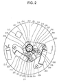
Fig. 2 is a rear view of a driving mechanism to be
used in the concrete example of the electronic timepiece
with indicator hands according to the invention.
Fig. 3 is an enlarged rear view of a driver
mechanism to be used in the concrete example of the
electronic timepiece with indicator hands according to the
invention.
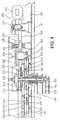
Fig. 4 is a B-B sectional view in fig. 2.
Fig. 5 is a partially enlarged sectional view of
Fig. 4
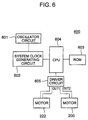
Fig. 6 is a block diagram of a driver circuit to be
used in the concrete example of the electronic timepiece
with indicator hands according to the invention.
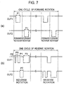
Fig. 7 is a timing view for explaining the
operation of the driver circuit shown in Fig. 6.
Fig. 8 is a front view showing an outside view of
another concrete example of an electronic timepiece with
indicator hands according to the present invention.
Fig. 9 is a front view showing an outside view of
another concrete example of an electronic timepiece with
indicator hands according to the present invention.
Fig. 10 is an E-E sectional view in Fig. 2.
Fig. 11 is a partially enlarged sectional view of
Fig. 10.
BEST MODE FOR CARRYING OUT THE INVENTION
Hereunder, concrete examples of electronic
timepieces with indicator hands according to the present
invention will be explained in detail with reference to
the drawings.
Fig. 1 is a front view showing an external view of
a concrete example of an electronic timepiece with
indicator hands according to the invention, showing an
example of electronic wristwatch. In Fig. 1 an electronic
wrist watch with indicator hands 100 has time hands of a
minute hand 101 and an hour hand 102 to represent a time
and provided with a first indicator hand 103 formed
integral with a crescent-shaped figure 105 and a second
indicator hand 104 formed integral with a star-shaped
figure 106. The indicator hands 103, 104 are arranged
between the minute hand 101 and hour hand 102 and the dial
107.
As described hereafter, by using two train wheels
having as a drive source a motor different from a motor
for driving the time hands 101, 102 to have a reduction
ratio corresponding to a second hand and transmitting
rotation opposite in direction with respect to the
indicator hands 103, 104, a pair of the indicator hands
103, 104 are each driven and rotated such that they
respectively reciprocate in opposite direction at the same
speed and in the same predetermined angle A.
Fig. 2 is a rear view showing a driver mechanism of
the electronic wrist watch with indicator hands 100 shown
in Fig. 1. Fig. 3 is an enlarged rear view showing the
driving mechanism of the electronic timepiece with
indicator hands shown in Fig. 1. Fig. 4 is a B-B
sectional view in Fig. 2 and Fig. 5 is a partially
enlarged sectional view of Fig. 4. In the figures, the
identical parts are given identical reference numerals.
In Fig. 2 to Fig. 5, between a support plate 202
and a main plate 201 structuring a support part, there are
accommodated the time hands of the minute hand 101 and the
hour hand 102, a driving mechanism to rotatively driving
the pair of indicator hands 103, 104 and an electronic
circuit. Concretely, they are structured as described
below.
A first stepping motor 200 structured by a coil
203, a stator 204 and a rotor magnet 205, is a well-known
stepping motor for a timepiece (see, for example, Japanese
Patent Laid-open No. 127365/1979). As described later,
this provides forward rotation drive and reverse rotation
drive so as to reciprocally rotate the indicator hands
103, 104 in directions opposite to each other within a
predetermined range (in an angular range A in Fig. 1).
The stator 204 and coil 203 are fixed on the main plate
201 with screws 207, 208.
The rotor magnet 205 has a gear 206 which is in
mesh with a gear 301 of a wheel 209. The wheel 209 has a
pinion 302 which is in mesh with a gear 303 of a wheel
210. Also, the gear 303 of the wheel 210 is in mesh with
a gear 306 of an hour wheel 212 to rotatively drive the
indicator hand 103.
On the other hand, a pinion 304 of the wheel 210 is
in mesh with a gear 305 of a wheel 211 for reverse
rotation. Also, the gear 305 of the wheel 211 is in mesh
with a gear 307 of the hour wheel 213 to rotatively drive
the indicator hand 104.
The wheel 211 has an elongate hole 225 formed along
a circumferential direction thereof. Due to this, ends
227, 228 are formed as a second engaging part in the wheel
211. A pin member 226 as a first engaging part is
inserted through the hole 225, which is planted and fixed
in a predetermined position on the main plate 201. The
ends 227, 228 of the wheel 211 and the pin member 226
constitute restricting means to restrict the range of
rotation of the indicator hands 103, 104. When the
indicator hands 103, 104 are about to rotate outside the
predetermined restricting range (e.g. angular range A in
Fig. 1), the pin member 226 and the end 227, 228 of the
wheel 211 comes into engagement to structurally restrict
the rotation of the indicator hands 103, 104.
Meanwhile, the wheels 209, 210 and the hour wheel
212 constitute a first train wheel to deliver rotation
reverse to a rotational direction of the stepping motor
200 (i.e. rotational direction of the rotor magnet 205) to
the first indicator hand 103. The wheels 209, 210, 211
and the hour wheel 213 constitute a second train wheel
which delivers rotation in the same direction as a
rotational direction of the stepping motor 200 to the
second indicator hand 104. Here, formed the same are the
gear ratio of the first train wheel of from the pinion 302
of the wheel 209 to the gear 306 of the hour wheel 212 and
the gear ratio of the second train wheel of from the
pinion 302 of the wheel 209 to the gear 307 of the hour
wheel 213. The indicator hand 103 and the indicator hand
104 are structured such that they are driven and rotated
at the same speed in directions opposite to each other.
This rotatively drives the crescent-shaped figure 105
formed integral with the indicator hand 103 and the star-shaped
figure 106 formed integral with the indicator hand
104 at the same speed in directions opposite to each
other.
Incidentally, the stepping motor 200, the wheels
209, 210, 211, the hour wheels 212, 213 constitute
rotation means for reciprocally rotating the first and
second indicator hands 103, 104 oppositely in a
predetermined range.
In the meanwhile, where the indicator hands 103,
104 are to be rotated in another way, i.e. where
continuously rotated the indicator hands 103, 104 are to
be in directions opposite to each other in a monotonous
fashion, the stepping motor 200 has to be driven and
rotated only in one direction. Furthermore, each wheel
requires change of rotation without restriction. At this
time, it is easy to change the way of rotation for the
stepping motor 200. However, because of the provision of
the pin member 226, a wheel having no hole 225 cannot be
arranged for replacement to a position of the wheel 211.
In order to solve this problem, the present
embodiment provides a space 230 to arrange a wheel 229
instead of the wheel 211 on the main plate 201, as shown
by the broken line in Fig. 2 and Fig. 3. The wheel 229 is
a wheel structurally the same as the wheel 211 and to be
used in place of the wheel 211. In the case the wheel 211
is removed and the wheel 229 is used, the wheels 209, 210,
229 and the hour wheel 213 constitute a third train wheel
to deliver rotation in the same direction as the
rotational direction of the stepping motor 200 (i.e.
rotational direction of the rotor magnet 205). Here, the
main plate 201 is not formed with an engaging part for
engaging the wheel 229 and there is no restriction of
rotation. Thus, the indicator hands 103, 104 are
controlled in rotation movement in accordance with
rotation of the stepping motor 200. Incidentally, because
the wheel 229 is not restricted in rotation, the wheel 229
can use a wheel having no hole. However, where other
movement is required, e.g. restricting the rotation of the
wheel 229, the wheel having a hole 229 can be utilized as
it is.
On the other hand, the electronic wristwatch 100
has drive means for rotatively driving the time hands of
the minute hand 101 and the hour hand 102. That is, it is
provided with a stepping motor 222 which is structured by
a coil 219, a stator 220 and a rotor magnet 221. Further,
a fourth train wheel structured by a wheel 214 to
rotatively drive wheels 223, 224 for delivering rotation
of the rotor magnet 221 and the minute hand 101 and an
hour wheel 215 to rotatively drive the hour hand 102.
The wheels 209, 210, 211 structuring each train
wheel are rotatably supported by the support plate 202.
Also, the hour wheels 212, 213, 215 are arranged
concentric on a shaft 216 formed integral with the wheel
214.
Also, an electronic circuit is incorporated which
comprises an integrated circuit 217 incorporating therein
a quartz oscillator 218 and driver circuit constituting an
oscillator circuit.
Fig. 6 is a block diagram of a driver circuit 600
used in one embodiment of an electronic timepiece with
indicator according, to the invention, wherein the same
reference numerals are given to the same parts of Fig. 2
to Fig. 5. In Fig. 6, the driver circuit 600 has an
oscillator circuit 601 comprising a quartz oscillator 218
or the like, a system clock generating circuit 602 for
generating a system clock from an output signal from the
oscillator circuit 601, a non-volatile read only memory
(ROM) 603 storing programs and motor driving pulses,
described hereafter, and constituting storage means, a
central processor unit (CPU) 604 to be operated by a
program stored in the ROM 603 in response to a system
clock from the system clock generating circuit 602 and
performs various operations and driving and controlling of
the stepping motor 200, 222, a driver circuit 605 for
supplying a drive signal to the stepping motor 200, 222, a
stepping motor 200 for driving and rotating the indicator
hands 103, 104, and a stepping motor 222 for driving and
rotating the minute hand 101 and the hour hand 102.
The ROM stores a drive pulse waveform shown in Fig.
7. Where driving the stepping motor 200 forward and
reverse, the CPU 604 reads the drive pulse out of the ROM
603 and drive the stepping motor 200 forward and reverse
through the driver circuit 605 (see, for example, the
aforesaid Japanese Patent Laid-open publication, for
example).
That is, in Fig. 7, where the stepping motor 200 is
rotated forward, it is rotated forward by applying a pulse
with a time width P1 to a terminal OUT1 as shown in Fig.
7(a). Next, a pulse with a time width P1 is applied to a
terminal OUT2 to cause forward rotation. This is
alternately repeated by one period (e.g. 10 times of
forward rotation), thereby repeating forward rotation of
the stepping motor 200.
Also, in that case of rotating the stepping motor
200 reverse, first a demagnetizing pulse with a time width
PE is supplied to the terminal OUT1 as shown in Fig. 7(b).
After a lapse of a time PS, a pulse with a time width P1
is supplied to once cause forward rotation. Thereafter, a
pulse with a time width P2 for reverse rotation is
supplied to the terminal OUT2, and thereafter a pulse with
a time width P3 for reverse rotation is supplied to the
terminal OUT1. This causes the stepping motor 200 to
rotate reverse. The above operation is made by one period
(e.g. 10 times of reverse rotation).
Thereafter, forward rotation and reverse rotation
as above, by one period each, are alternately made to
cause the stepping motor 200 to rotate forward and reverse
by a same predetermined amount a time. This is repeated.
This rotatively drive the rotor magnet 205 of the
stepping motor 200 alternately in forward and reverse
directions by a same amount a time.
If the stepping motor 200 is rotated forward (in
the arrowed direction in Fig. 3) by a predetermined number
of times, the wheel 209, the wheel 210, and the hour wheel
212 rotate in respective arrowed directions. Due to this,
the indicator hand 103 rotates by an angular rage A in the
arrowed direction (clockwise). Simultaneously, the wheel
211 in mesh with the wheel 210 rotates in the arrowed
direction to rotate the hour wheel 213 in the arrowed
direction, rotating the indicator hand 104 by the angular
range A in the arrowed direction (counterclockwise).
Next, when the stepping motor 200 rotates reverse
(in a direction opposite to the arrow in Fig. 3) by the
predetermined number of times, the wheel 209, the wheel
210, and the hour wheel 212 rotate in a direction opposite
to the arrow. Due to this, the indicator hand 103 rotates
by the angular range A. Simultaneously, the wheel 211 in
mesh with the wheel 210 rotates in a direction opposite to
the arrow. This causes the hour wheel 213 to rotate in a
direction opposite to the arrow, rotating the indicator
hand 104 by the angular range A in the direction opposite
to the arrow (clockwise).
Thereafter, the above movement is repeated. Due to
this, the crescent-shaped figure 105 integral with the
indicator hand 103 and the star-shaped figure 106 integral
with the indicator hand 104 reciprocally move at the same
speed in directions opposite to each other in the same
angular range A. Incidentally, the range of rotation of
the indicator hand 103, 104, i.e. the range of rotation
angle A in Fig. 1 is determined by the amount (number) of
forward and reverse rotation of the stepping motor 200.
By setting a rotation amount of the stepping motor 200 in
various ways, the rotational range of the indicator hand
103, 104 can be set variously. Accordingly, it is
possible to reciprocally rotate the crescent figure 105
and the star figure 106 in a variety of ranges.
When the indicator hands 103, 104 are reciprocally
move normally within the angular range A in the above
manner, in the event that the indicator hand 103, 104
irregularly move due to mechanical impact or the like and
moves toward an outside of the angular range A, the wheel
211 rotates due to rotation of the indicator hands 103,
104. However, the ends 227, 228 of the wheel 211 formed
by the hole 225 engages the pin member 226, thus
restricting the indicator hand 103, 104 from rotating
furthermore. This can prevent the indicator hands 103,
104 from moving abnormally.
Fig. 8 is a front view showing an external view of
another concrete example of an electronic timepiece with
indicator hands according to the invention. The identical
parts to Fig. 1 are given the identical reference
numerals.
In Fig. 8, an electronic wristwatch with indicator
hands 100 has time hands comprising a minute hand 101 and
an hour hand 102 and provided with a first indicator hand
103 formed integral with an arrowed figure 801 and a
second indicator hand 104 formed integral with a heart-shaped
figure 802. The indicator hands 103, 104 are
arranged between the minute hand 101 and the hour hands
102 and the dial 107. The a pair of indicator hands 103,
104 are each driven and rotated to reciprocally move at
the same speed in directions opposite to each other within
the same predetermined range of angle C.
Fig. 9 is a front view showing an external view of
another concrete example of an electronic timepiece with
indicator hands according to the invention. The identical
parts to Fig. 1 and Fig. 8 are given the identical
reference numerals.
In Fig. 9, an electronic timepiece with indicator
hands 100 has time hands comprising a minute hand 101 and
an hour hand 102 and also is provided with a first
indicator hand 103 formed integral with an arrowed figure
801 and a second indicator hand 104 formed integral with a
heart-shaped figure 802. The indicator hands 103, 104 are
arranged between the minute hand 101 and hour hands 102
and the dial 107. A pair of indicator hands 103, 104 are
each driven and rotated to reciprocally move at the same
speed in directions opposite to each other within the same
predetermined range of angle D.
As shown in Fig. 1, Fig. 8, and Fig. 9, a variety
of representations can be provided by making the figures
put on the indicator hands 103, 104 with various figures
such as characters or letters, changing the attaching
angle to the indicator hand 103, 104 or changing the range
of rotational angle of the indicator hand 103, 104.
Next, where the indicator hands 103, 104 are to be
rotated in movement other than the reciprocal movement,
e.g. where the indicator hands 103, 104 are to be rotated
monotonously in directions opposite to each other, the
wheel 211 is removed and a wheel 229 is attached and used
in place thereof in a space 230 of a support part 202 as
shown by the broken line in Fig. 2 and Fig. 3.
Also, due to this, the motor 200 is driven and
rotated only in one direction. For example, the ROM 603
of Fig. 6 is replaced with the ROM storing only the
forward rotation pulse of Fig. 7(a), and the pulse stored
in the ROM is read out by a CPU 604 to rotatively drive
the motor 200, thereby driving and rotating the motor 200
only in one forward direction. Alternatively, the ROM 603
of Fig. 6 is replaced with the ROM storing only the
reverse rotation pulse of Fig. 7(b), and the pulse stored
in the ROM is read out by the CPU 604 to rotatively drive
the motor 200, thereby driving and rotating the motor 200
only in one reverse direction.
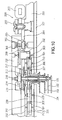
Fig. 10 is an E-E sectional view of Fig. 2 showing
a structure in which that the wheel 211 is replaced with a
wheel 229 as stated above, and Fig. 11 is an enlarged
sectional view of Fig. 10. In Fig. 10 and Fig. 11, the
identical parts to Fig. 1 to Fig. 5 are given the
identical reference numerals. Explanation is made below
mainly on the parts different from them.
In Fig. 10 and Fig. 11, the rotation of the rotor
magnet 205 is delivered to the hour wheel 212 for driving
and rotating the indicator hand 103 through the gear of
the rotor magnet 206, the gear 301 of the wheel 209, the
pinion 302 of the wheel 209 and the gear 303 of the wheel
210. Due to this, the indicator hand 103 rotates reverse
to the rotor magnet 205.
Also, the rotation of the rotor magnet 205 is
delivered to the hour wheel 213 for driving and rotating
the indicator hand 104 through the gear of the rotor
magnet 206, the gear 301 of the wheel 209, the pinion 302
of the wheel 209 and the gear 308 of the wheel 229. Due
to this, the indicator hand 104 rotates in the same
direction as the rotor magnet 205.
As described before, if the motor 200 is rotated
only in one direction, there is no restriction by the
restricting means. Accordingly, the figure integrally
provided on the indicator hand 103 (the crescent figure
105 in Fig. 1, or the arrowed figure 801 in Fig. 8 and
Fig. 9) is repeatedly rotated reverse to the stepping
motor 200, and the figure integrally provided on the
indicator hand 104 (the star figure 106 in Fig. 1, or the
heart-shaped figure 802 in Fig. 8 and Fig. 9) is
repeatedly rotated in the same direction as the stepping
motor 200. This can provides different display from the
reciprocal movement stated before.
As stated above, the electronic wristwatch with
indicator hands 100 according to the concrete example of
the invention is characterized by having, particularly,
the time hands 101, 102 to show a time, the first and
second indicator hands 103, 104 provided separate from the
time hands 101, 102, the stepping motor 200 to rotate
forward and reverse by a predetermined amount a time, the
train wheel for delivering rotation of the stepping motor
200 and reciprocally rotating the first and second
indicator hands 103, 104 in directions opposite to each
other within a predetermined range, the support part (the
main plate 201, the support plate 202) supporting the
wheels constituting the train wheel, and the restricting
means (the pin member 226, the ends 227, 228) for
restricting range of the wheel 211 included in the train
wheel to thereby restrict the rotation of the indicator
hands 103, 104 in a predetermined restriction range,
wherein the support part is formed with the space 230 for
arranging the other wheel 229 to enable the provision of
the other wheel 229 in the train wheel in place of the
wheel 211 to be restricted in rotation range by the
restricting means.
Accordingly, where the wheel 211 is used, a variety
of representations are possible by the reciprocal motion
of the indicator hands 103, 104. Furthermore, it is
possible to provide an electronic wristwatch 100 with
indicator hands capable of restricting the indicator hands
103, 104 from abnormally moving due to impact or the like.
For example, it is possible to represent movement
of action in a certain predetermined range, e.g.
integrally forming character's hands or legs on each of
two indicator hands 103, 104, and to restrict the
indicator hands 103, 104 from abnormally moving. Also,
where integrally forming figures of both hands on the
indicator hands 103, 104, the both hands may be
reciprocally moved in a rattling fashion in a
predetermined range of movement or the indicator hands
103, 104 may be set variously in attaching angle, thereby
making it possible to represent such motion that the
character shows largely waving its hand or clapping its
hands and restrict the indicator hands 103, 104 from
abnormally moving.
Furthermore, by arranging the indicator hands 103,
104 between the time hands (minute hand 101, hour hand
102) and the dial 107, these can be provided with a sense
of unity with the design on the dial 107.
Meanwhile, with altering by removing the wheel 211
and attaching another wheel 229 in the space 230 of the
support plate 202 as well as altering to make the motor
200 perform other rotational movement, an electronic
wristwatch with indicator hands 100 can be provided having
indicator hands 103, 104 capable of indicating in further
various ways. For example, if the motor 200 is altered to
rotatively drive only in one direction, it is possible to
change the motion of the first and second indicator hands
103, 104 to different motion from the reciprocal motion
within a predetermined range, i.e. motion of monotonously
rotating in directions opposite to each other. Thus, an
electronic wristwatch with indicator hands 100 can be
provided having indicator hands 103, 104 capable of
indicating in further various ways.
Also, by structuring the diameter or gear or tooth
count of the wheel 229 same as or different from the wheel
211, further a variety of indications are made possible.
Incidentally, in each of the above-described
concrete examples, although the motor used a stepping
motor 200 for timepieces structured by the coil 203, the
stator 204 and the rotor magnet 205, a motor of another
structure may be used.
Also, in each of the above-described concrete
examples, although the indicator hands 103, 104 were made
to rotate at the same speed, they may be rotated at speeds
different from each other.
Furthermore, in each of the above-description
concrete examples, although the indicator hands 103, 104
were same in rotation range, different ranges may be
given.
Furthermore, in each of above-described the
concrete examples, the time hands were structured by the
minute hand 101 and the hour hands 102, a second hand may
be added thereto.
Also, although the restricting means was structured
by the ends 227, 228 of the wheel 211 and the pin member
226 fixed on the main plate 201, the pin member 226 may be
formed on the side of the support plate 202. It is also
possible to form a pin member on the wheel 211 and
structurally form a hole or recess in the main plate 201
or support plate 202. The restricting means can adopt a
variety of structures capable of restricting the rotation
range of the indicator hands 103, 104 to a predetermined
restriction range.
INDUSTRIAL APPLICABILITY
As described above, the electronic timepiece with
indicator hands according to the present invention is
applicable to various electronic timepieces beginning from
electronic wristwatches to wall-type electronic timepieces
and desk-top electronic timepieces.