EP1164369A2 - Ootical reading apparatus and optical reading method - Google Patents
Ootical reading apparatus and optical reading method Download PDFInfo
- Publication number
- EP1164369A2 EP1164369A2 EP01305076A EP01305076A EP1164369A2 EP 1164369 A2 EP1164369 A2 EP 1164369A2 EP 01305076 A EP01305076 A EP 01305076A EP 01305076 A EP01305076 A EP 01305076A EP 1164369 A2 EP1164369 A2 EP 1164369A2
- Authority
- EP
- European Patent Office
- Prior art keywords
- light
- photo
- subject
- receiving element
- optical
- Prior art date
- Legal status (The legal status is an assumption and is not a legal conclusion. Google has not performed a legal analysis and makes no representation as to the accuracy of the status listed.)
- Withdrawn
Links
Images








Classifications
-
- G—PHYSICS
- G01—MEASURING; TESTING
- G01N—INVESTIGATING OR ANALYSING MATERIALS BY DETERMINING THEIR CHEMICAL OR PHYSICAL PROPERTIES
- G01N21/00—Investigating or analysing materials by the use of optical means, i.e. using sub-millimetre waves, infrared, visible or ultraviolet light
- G01N21/84—Systems specially adapted for particular applications
- G01N21/88—Investigating the presence of flaws or contamination
- G01N21/8851—Scan or image signal processing specially adapted therefor, e.g. for scan signal adjustment, for detecting different kinds of defects, for compensating for structures, markings, edges
Definitions
- the present invention relates to methods and apparatus for optically reading information, and specifically relates to an optical reading apparatus and an optical reading method for obtaining objective information by reading a subject and processing the read information through an arithmetic processing.
- the objective information when deriving the objective information from optical information read optically, the objective information is detected or recognized by applying a processing-operation, such as an image-analyzing operation, etc., to signals obtained by reading the optical information.
- a processing-operation such as an image-analyzing operation, etc.
- the barcode recognition, the character recognition, the shape recognition, etc. are included in the above operation.
- noise components caused by an optical mechanism are included in opt-electronic conversion results outputted by the optical reading apparatus, which comprises a light source, a photo-receiving element and a calculating means, and irradiates a light bundle emitted from the light source onto the subject, and opt-electronically converts its reflected light or its transmitted light with the photo-receiving element, and then, detects the information of the subject by applying the an arithmetic processing to the signals converted opt-electronically.
- the optical reading apparatus which comprises a light source, a photo-receiving element and a calculating means, and irradiates a light bundle emitted from the light source onto the subject, and opt-electronically converts its reflected light or its transmitted light with the photo-receiving element, and then, detects the information of the subject by applying the an arithmetic processing to the signals converted opt-electronically.
- the signals opt-electronically converted by the photo-receiving element include noise components, caused by an optical mechanism, which is overlapped with the concave or convex information as a detecting subject.
- noise components caused by optical factors is larger than the opt-electronically converted signals, etc., and, for instance, characters and numerals formed in either the convex or the concave are detected/recognized by detecting the aforementioned convex or concave formed on the surface of the subject, and various kinds of patterns printed or residing on the surface of the subject works as noise components caused by optical factors, such the noise components considerably impede an accurate reading action for the information, which include deviations of the convex or the concave as a detecting object.
- the information, being a detecting object of the subject is at least one of the convex or the concave formed on the surface of the subject
- the noise components caused by optical factors, such as the distribution of reflecting rates or the distribution of transmitting rates exist on the surface of the subject, when detecting them with a reflected light or a transmitting light
- the noise components, caused by such as colors and density patterns, etc. which influences to the reflecting rate or the transmitting rate on the surface of the subject, are integrated with the detected signals including the information of the convex or the concave being the detecting object.
- the noise components are the optical information caused by optical factors
- the present invention is attained in view of the abovementioned problems in conventional optical reading apparatus and optical reading methods.
- a method and an apparatus in which objective information are obtained by optically reading the subject and applying arithmetic processing, it is an object of the present invention to reduce the influence of the noise components caused by optical factors and to improve the accuracy of the necessary information being a detecting object.
- a plurality of photo-receiving elements are symmetrically disposed, and the photo-receiving results of the plurality of photo-receiving elements are synthesized or selected to cancel the noise components caused by the optical factors, and as a result, the influence of the noise components is suppressed.
- Fig. 1 shows a block diagram of an exemplified configuration of an optical reading apparatus embodied in the present invention.
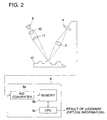
- the reflected light strength of the subject is measured, in order to perform an arithmetic processing for discriminating and classifying papers based on the reflecting rate of the paper.
- the measurement is performed under light source 1, such as a room light, a fluorescent light in the vicinity, or illumination light equipped with the photo-receiving element, etc.
- light source 1 such as a room light, a fluorescent light in the vicinity, or illumination light equipped with the photo-receiving element, etc.
- PSD 4 Positioning Sensitive Detector 4
- shadow portion 5 of subject 2 such as a box, etc.
- computer 8 erroneously determines that subject 2, such as a box, etc., has a very low reflecting rate.
- comparator 7 eliminates data lower than a predetermined light intensity from the stored data by performing logical judgments. Then, computer 8 performs the arithmetic processing in regard to optical data from which the data equivalent to the shadow portion is eliminated. Thus, it becomes possible to precisely determine subject 2.
- PSD 4 a CCD (Charge Coupled Device) and a PD (Photo Detector) can be employed for photo-receiving element.
- the threshold value employed for comparator 7 is prescribed at an intermediate value between a minimum lightness value of the background color (overall reflecting rate) of the paint, etc., equipped on the surface of subject 2, and the lightness value of shadow portion 5.
- the optical reading apparatus comprises at least a photo-receiving element, such as PSD 4, etc., and opt-electronically converts the received light in such a manner that the light reflected from subject 2 enters into PSD 4 under light source 1, such as the room light, etc., and applies processing, equivalent to mathematic logical calculations, such as a differential calculus, an integral calculus, sum and subtract calculus, etc., to noise components caused by an optical mechanism (in this embodiment, generated at the shadow portion) with simpler arithmetic elements and circuits, to obtain the optimum signals.
- a photo-receiving element such as PSD 4, etc.
- the abovementioned noise components caused by an optical mechanism can be classified in the following categories.
- noise components caused by the optical factors, cited in any one of abovementioned items 1 - 3, can be eliminated by the arithmetic processing performed in computer 8, or can be electronically eliminated by the arithmetic operations performed by the operational amplifier, etc. equipped in an exclusive processing circuit.
- A/D converter 8a converts the output analogue signals of PSD 4 to digital data
- memory 8b stores the digital data of the optical information
- CPU 8c performs the arithmetic processing based on software (execution of program) by using the stored digital data.
- CPU 8c includes both functions of an elimination calculating means for reducing or eliminating the noise components, and a calculating means for performing arithmetic processing to detect the information of the subject under detection.
- the intensity of the received light abruptly decreases, and therefore, the computer erroneously determines that the subject has a very low reflecting rate.
- the data lower than a predetermined light intensity is reduced from the stored data at the initial stage of the arithmetic processing by performing logical judgments.
- the signals are initially processed to obtain waveforms without noise components, namely, the noise components are initially removed from the original signals by calculating with data stored in the memory.
- the signals, from which noise components are already removed are encoded into binary or multivalued data to conduct the image processing, it is possible to precisely detect the information under the detecting operation, and further, the abovementioned method is superior to conventional methods for discriminating a shape or letters by applying an arithmetic filtering processing afterward to two-dimensional information stored in advance.
- the photo-receiving element is a PSD or the like being detectable of the position of the received light
- the light source is a Laser Diode (a LD)
- the irradiation light is a linear light obtained by shaping the light bundle, emitted from the light source, with cylindrical lens 11, etc.
- the subject is card 12, which moves at a constant velocity and comprises at least one of a concave and a convex, and the received light, being the linear light corresponding to at least one of the concave and the convex, enters into PSD 4.
- CPU 8c calculates Fresnel diffraction component 15 in accordance with a theory for deriving the light diffraction from the distance between the edge at which the light is eclipsed and the photo-receiving element, and then, subtract the derived value from the output data of the photo-receiving element stored in memory 8b to obtain signal component 14, it becomes possible to perform precise measurements and judgments.
- Fig. 4 shows a perspective view of the configuration of the apparatus embodied in the present invention.
- the irradiation light emitted from the light source is shaped into a liner light by cylindrical lens 11, and the liner light is irradiated onto subject 2.
- subject 2 is a card comprising black area 2a and white area 2b.
- the liner light comprises liner light center area 17, which is located at its center portion and has a strong light intensity, and liner light diffusion area 18, which is an area diffused around liner light center area 17 and has a relatively weak light intensity.
- liner light center area 17 resides within black area 2a, while a part of liner light diffusion area 18 resides within white area 2b.
- a part of liner light diffusion area 18 enters onto white area 2b, and the light reflected from white area 2b is collected by collecting lens 3, so as to enter into PSD 4.
- Fig. 4 the light, entering into the incident surface of PSD 4, is illustratively indicated.
- Numeral 21 is a white image of white area 2b projected by liner light diffusion area 18, and
- numeral 22 is a black image of black area 2a projected by liner light center area 17.
- the information of subject 2 under the detecting operation is information in respect to at least one of the concave and the convex on the surface
- the light of liner light diffusion area 18 reflected from white area 2b generates the noise components caused by the optical factors.
- the noise components caused by the optical factors are the information other than the information of subject 2 under the detecting operation, and the information arise from the distribution of reflecting rates or the distribution of transmitting rates (refer to Fig.
- CPU 8c serving as an elimination calculating means, can detect the noise components based on the difference of frequency components of the digital data opt-electronically converted by PSD 4.
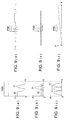
- signal Sa and signal Sb both of which have approximately the same optical frequency, exist in appearance.
- signal Sa represents the required signals derived from the convex or the concave of the card
- signal Sb represents the noise components caused by the optical factors.
- signal Sa is caused by the optical variations having a frequency lower than that of signal Sb, sometimes, signal Sa and signal Sb emerge at the same frequency as a result. Therefore, the noise components cannot be eliminated by means of electronic filters, but can be eliminated only by calculating the optical data as mentioned above.
- Fig. 5(c) exemplifies a case that the noise components caused by the optical factors are high frequency components.
- the second embodiment in which an operation for separating the optical information, being as a detecting object, from the noise components caused by the optical factors is performed based on the centroid of the reflected light, will be detailed in the following.
- the optical reading apparatus characterized in that the influence of the noise components is reduced by calculating quasi surface deviations of the convex or the concave (hereinafter, referred to as the quasi-deviation) including noise components associating with the distribution of reflecting rates caused by the density variation, which are the same kind of non-detected information of the subject, aforementioned referring to Fig. 2 and Fig. 4.
- the variation of reflecting rates on the surface of the subject caused by the information, being different from the information of the detecting object could be the cause of a big confusion in respect to the information of the detecting object.
- the amplitude of which is equivalent to or larger than that of the original signals to be obtained is outputted from the photo-receiving element in a state of overlapping each other, it is virtually impossible to eliminate the quasi-signals in advance only by its mechanism and/or optical configuration.
- the arithmetic processing operation performed by CPU 8c is a kind of the simulation calculating operation.
- the photo-receiving element is such the element as PSD 4 being capable of detecting the centroid of the received light
- the light source is the LD (Laser Diode)
- the illumination light is a linear light formed by shaping the light bundle emitted from the light source with the cylindrical lens, etc.
- the subject 2 is a card-type subject, which moves at a constant velocity and comprises at least one of a concave and a convex
- PSD 4 can receive the linear light corresponding to the convex or the concave projected on PSD 4, is assumed as a concrete example of the second embodiment.
- Fig. 15 shows an embodiment of an optical reading apparatus for detecting the distribution of the concave variations of card 2 comprising plain portion ⁇ and concave portion ⁇ .
- the positions of PSD 4, collecting lens 3, etc. are determined at such positions that the light, reflected from plain portion ⁇ , forms spot 100a at substantially the center of PSD 4, as shown in Fig. 16(a), when the light emitted from LD 9 is irradiated onto plain portion ⁇ .
- the centroid position of the reflected light is located at the center of PSD 4.
- the light reflected from concave portion ⁇ forms spot 100b at a position shifted from the center of PSD 4, as shown in Fig. 16(b).
- the two electronic currents outputted from the both ends of PSD 4 exhibit different values, namely, the value of the electronic current outputted from the end near the spot 100b is greater than that outputted from the other end of PSD 4 (in Fig. 16(b), I 1 > I 2 ).
- the centroid position of the reflected light is located at the position shifted from the center of PSD 4.
- the light reflected from plain portion ⁇ forms spot 100c at substantially the center of PSD 4 as well as the case of irradiating the light onto plain portion ⁇ , as shown in Fig. 16(c).
- displacement information of the photo-receiving position can be obtained by employing the PSD, and thereby, the distribution of displacement variations on the concavo-convex portion can be detected.
- the value derived from (I 1 - I 2 ) / (I 1 + I 2 ) is employed as the displacement information of the subject.
- the equation of X A (I 1 - I 2 ) / (I 1 + I 2 ) gives the displacement information of the subject at the light irradiating point.
- X A can be regarded as a value, which indicates the centroid position of the light on PSD 4 in its X-direction.
- CPU 8c calculates the centroid position of the reflected light of the noise components (noise components caused by the optical factors), disturbing as the quasi-signals, from the optical information being in proportion to the distribution of reflecting rates by performing the elimination calculating processing, and subtracts the calculated result from the centroid position of the reflected light, which is directly derived from the light received on the PSD at first by performing the calculating processing. Then, it is possible to obtain the high-accurate optical information of at least one of the convex and the concave by performing a normal arithmetic processing in respect to the signals in which the noise components caused by the optical factors are reduced.
- PSD 4 has a plurality of output ports to calculate the centroid position of the received light.
- the one-dimensional PSD outputs two electronic currents from its both ends, each of which is in inverse proportion to the distance from the end to the centroid position of the light received on the element.
- the sum of the two electronic currents is in proportion to the intensity of the light reflected from the surface of the card after emitted from the LD, serving as a light source, and the information of the sum of the outputs in a time passage domain can be regarded as being equivalent to the information of the distribution of reflecting rates.
- the approximate noise components, serving as quasi-signals of outputs of PSD 4 can be obtained by applying a predetermined arithmetic processing to the information mentioned above.
- the surface of card 2 comprises a bright portion (white area 2b), from which more than 90% of the incident light is reflected or diffused, and a dark portion (black area 2a), from which less than several % of the incident light is reflected or diffused, and linear light spot 170 is irradiated onto the surface of card 2 by using the apparatus shown in Fig. 15. Further, card 2 moves in a direction designated by the arrow.
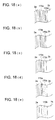
- Figs. 18(a)-18(e) show variations of linear light spot 170 varying with time, when linear light spot 170 moves in the vicinity of the border of white area 2b and black area 2a, both of which are a plain surface, under the abovementioned situation. At that time, linear light spot 170 is reflected by the surface of card 2, and the reflected light is received on PSD 4 (in this embodiment, the one-dimensional PSD).
- Figs. 19(a)-19(e) show variations of the light spot received on PSD 4 with time.
- PSD 4 can detects not only a position of receiving the light, but also a quantity of the light, the relationship between electronic currents I 1 and I 2 outputted from PSD 4 can be established as I 1 > I 2 , due to unevenness of the brightness intensity within the light spot. Accordingly, PSD 4 detects the position of the light spot as if it would deviate from the center to the right direction (+x direction from the center), resulting in generation of noise components due to the distribution of reflecting rates caused by the density contrast of card 2. In addition, it can be stated for this situation that the centroid of the light deviates from the center to the right direction (+x direction from the center) (in the drawing).
- PSD 4 detects the position of the light spot as if it would deviate from the center to the right direction.
- X A (I 1 - I 2 ) / (I 1 + I 2 ) in Fig. 19(c) is smaller than that in Fig. 19(b), namely, the deviation of the centroid of the light in Fig. 19(c) is less than that in Fig. 19(b).
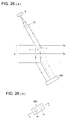
- Fig. 20 shows a graph of the variation of centroid position XC versus the moving position of card 2 in the example shown in Figs. 18(a)-18(e) and Figs. 19(a)-19(e), indicating moving distance L of card 2 in the horizontal axis and centroid position XC of the light in the vertical axis, respectively.
- the waveform portion illustrated in Fig. 20 represents noise components generated by the distribution of reflecting rates caused by the density contrast of card 2, namely, the quasi-signals.
- each position of symbols (a)-(e) indicated in Fig. 20 correspond to each of Figs. 18(a)-18(e) and Figs. 19 (a) -19 (e) .
- the information representing the distribution of reflecting rates of the subject overlap with the information representing the distribution of the concavo-convex deviations of the subject. Then, it becomes possible to extract the information of the centroid of the light caused only by the distribution of the concavo-convex deviations of the subject, by subtracting the centroid of the light caused by the distribution of reflecting rates from the centroid of the light received on the photo-receiving element X A . In short, it becomes important to obtain the centroid of the light caused by the distribution of reflecting rates.
- the centroid of the light caused by the distribution of reflecting rates can be derived from the sum of two electronic current or voltage values outputted from the both ends of the PSD.
- the present inventors have discovered that the centroid of the light caused by the distribution of reflecting rates can be derived from the information of a total light quantity of the light spot. That will be detailed in the following.
- the quantity of the light irradiated onto the PSD is maintained at constant value, even if the light receiving position on the PSD varies in accordance with the concavo-convex deviations on the surface of the subject.
- the quantity of the light irradiated onto the PSD varies in accordance with the variations of the reflecting rate on the surface of the subject. Accordingly, the sum of two electronic current values (or voltage values), outputted from the both ends of the PSD, is irrespective of the concavo-convex deviations on the surface of the card, but varies in proportion to the reflecting rate on the surface of the subject.
- Figs. 17-20 is exemplified in the following explanation.
- FIG. 21 shows a variation (or a variation in a passage of time) of the sum of two electronic current values versus the moving position of the card in the example shown in Figs. 17-20.
- the sum of two electronic current values can be also regarded as the total light quantity of the light spot on the PSD.
- moving distance L of the card is plotted on the horizontal axis
- each position of symbols (a)-(e) indicated in Fig. 21 correspond to each of Figs. 19(a)-19(e).
- the sum of two electronic current values is corresponded to each moving distance L of the card, and for instance, sum Q at each moving distance L is memorized in a memory.
- the sums of two electronic current values are defined as Q 1 , Q 2 , ----, Q m , Q m+1 , Q m+2 , ----, Q m+u , ----, Q n , each of which corresponds to each of the moving distances defined as L 1 , L 2 , ----, L m , L m+1 , L m+2 , ----, L m+u , ----, L n .
- the width of the light spot on the card is "L m+u - L m ".
- the centroid of the light caused by the distribution of reflecting rates can be derived from the above data. Since the variation of the centroid of the light caused by the distribution of reflecting rates occurs based on the unevenness of the light quantity within the light spot received on the PSD, it is possible to find the centroid of the light caused by the distribution of reflecting rates by determining the centroid of the light within the width of the light spot received on the PSD at each of the moving distances of L 1 , L 2 , ----, L m , L m+1 , L m+2 , ----, L m+u , ----, L n .
- centroid XC(m) of the light within the width of the light spot received on the PSD, caused by distribution of reflecting rates can be expressed as follow.
- XC(m) K ⁇ ((L m+1 - L m ) ⁇ Q m+1 +---+ (L m+u - L m ) ⁇ Q m+u ) / (Q m + Q m+1 + Q m+2 +---+ Q m+u )
- K is a magnifying power of image formation.
- the time interval for obtaining the sum of electronic current values is such an interval that the moving distance of the card during one interval is shorter than the width of the light spot.
- Fig. 22 shows a graph of the relationship between the moving distance and the centroid of the light within the width of the light spot received on the PSD (XC(m)), the centroid of the light being found at each of the moving distances of L 1 , L 2 , ----, L m , L m+1 , L m+2 , ----, L m+u , ----, L n . Since the graph in respect to the plain portion having no concavo-convex is depicted in Fig. 20, the shape of the graph shown in Fig. 20 is substantially the same as that of the graph shown in Fig. 22.
- the calculating processing means performs the abovementioned processing, and then, the calculating processing means conducts calculating processing for the signals, in which the noise components are reduced, to detect the information of the distribution of concavo-convex deviations of the subject.
- the photo-receiving element is not limited to the one-dimensional PSD.
- the calculating processing means or the subtracting processing means comprises a MPU (micro processing unit), a CPU (central processing unit), a Customized LSI, a Gate Array, etc.
- the subtracting processing means also comprises a memory, for which an analogue memory and/or a digital memory can be employed.
- a digital memory it is desirable that the signals, generated by the opt-electronic converting action of the photo-receiving element, are converted to digital data by the analogue-to-digital converting operation to store the digital data in the digital memory.
- the signals, generated by the opt-electronic converting action of the photo-receiving element, can be directly stored in the analogue memory without performing the analogue-to-digital converting operation.
- a collecting lens having no directivity in the light collecting action can be also employed.
- the card comprises a bright surface portion, from which more than 90% of the incident light can be reflected or diffused, and a dark surface portion, from which less than several percent of the incident light can be reflected or diffused.
- the intensity of the light is attenuated as the irradiated linear light leaves from its center.
- the width of the low intensity area of the light unexpectedly becomes large.
- PSD 4 receives the light including the abovementioned component, PSD 4 outputs such signals that the centroid of the light is located at a position, which is separated at distance ⁇ F (refer to Fig. 4) from the position, at which the image of linear light center area 17 is formed, in the side area on which the image of the high-reflective portion on the card (white area 2b) is formed (refer to Fig. 7).
- the time passage distribution of the sum of the output values indicates a coarse approximation of the distribution of real reflecting rates.
- the centroid position of the quasi-signals caused by the distribution of reflecting rates is found as an independent value hardly relating to the centroid position by the essential linear light.
- This quasi-signals are main components of the noise, and it is possible to precisely obtain the original signals by simply removing this approximated quasi-signals.
- calculated value P depicts a carve like a triangle waveform as shown in Fig. 8 (a).
- PSD 4 works as a kind of a low-pass filter in respect to the aforementioned distribution of reflecting rates, namely, components calculated from the light received on all area of the PSD 4.
- PSD 4 works in reality based on complicated actions being different from those of electronic low-pass filters.
- a moving range of the subject in both upper and lower directions is limited so that the reflected light of the linear light does not enter the edge portions of the PSD, in order to prevent the above phenomenon.
- the PSD is a kind of low-pass filter, and the distribution of reflecting rates (components of the quasi-signals calculated from the light outputted from all of the PSD) would belong to a low-frequency band.
- the output of the PSD can be regarded as a component synthesized into the abovementioned two frequency-bands (the quasi-signals in the low-frequency band, desired signals having a frequency other than the low-frequency band). Therefore, it becomes possible to obtain the information (the information of the deviations of at least one of the convex or the concave) of the subject, in which the influence of the quasi-signals is reduced, by reducing the noise components (the quasi-signals) caused by the optical mechanism by conducting the elimination calculating processing, as a separate arithmetic processing, before conducting the arithmetic processing.
- the signals relevant to the convex or the concave being a detecting object with reduced noise components, was derived from the signals (the signals including the quasi-signals, serving as noise components) outputted from PSD 4 caused by the variation of reflecting rate generated by the information of the density contrast on the surface of subject 2.
- the two electronic current values I1, I2 outputted from the both ends of PSD 4 are converted to signal V1 and signal V2 through the processes of the I/V conversion, the amplifying operation and the A/D conversion, and then, signal V1 and signal V2, as time passage information, are stored in the memory during the moving action of subject 2.
- a plurality of signals employed for calculating each shift amount ⁇ F are quantities corresponding to the width of the illumination light emitted from the LD (the light source) onto subject 2 (width share (time share) of the light spot or the linear light of the illumination light in the moving direction of subject 2 at each reading timing).
- each signal of the centroid position based on the convex or the concave, being a detecting object with reduced noise components was found. This corresponds to the centroid position derived from signal I1' and signal I2', outputted from PSD 4, in which the noise components to be approximated at the essential position are reduced, based on the convex or the concave being a detecting object.
- PD array 4 comprises PD 41 and PD 42 which are adjacent each other. Then, when the light is focused onto the area of level Ca as shown in Fig. 24(a), since an amount of the light irradiated onto PD 42 is larger than that irradiated onto PD 41 as shown in Fig. 25(a), electronic current I 2 generated by PD 42 is larger than electronic current I 1 generated by PD 41.
- the apparatus comprises light source 9, collimator lens 10 for collimating the light flux emitted from light source 9 to irradiate subject 2, and PSD 400 for receiving the transmitted light penetrated through the subject.
- the PSD having a two-dimensional photo-receiving surface or a solid-state imager having a two-dimensional photo-receiving surface (a CCD or a MOS imager) for the photo-receiving element in the abovementioned apparatus.
- the outputs of the photo-receiving element in a time passage domain are in proportion to the distribution of reflecting rates of the subject, and it is possible to conduct the aforementioned subtracting operation based on the information of the outputs of the photo-receiving element stored within a short time. Therefore, it becomes possible to complete the arithmetic processing more quickly than in the method of finding the distribution after storing all of the information in the memory. Further, since the quantity of the information is large, it becomes possible to apply other various kinds of filters for the arithmetic processing. Still further, it becomes possible to conduct the detecting operation not only for the linear-type detecting object, but also for the two-dimensional detecting object at a time.
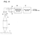
- ANOTHER EMBODIMENT 2 shown in Fig. 11 the laser beam emitted from the light source (not shown in the drawing) is focused onto subject 2, and optical system 50 collects the light diffused and reflected from subject 2 and guides the diffused and reflected light to first segment 52 and second segment 53 of the multi-segmented photo-diode, serving as a photo-receiving element. Then, subtracting circuit 54 generates the difference information between output values of first segment 52 and second segment 53 of the multi-segmented photo-diode. The information of at least one of the convex or the concave of subject 2 is detected by the relationship of the distance with subject 2. According to the configuration shown in Fig.
- knife-edge 51 is disposed in front of the multi-segmented photo-diode, and the balance of photo-receiving results of first segment 52 and second segment 53 of the multi-segmented photo-diode varies depending on at least one of the convex or the concave of subject 2, it is possible to detect at least one of the convex or the concave of subject 2.
- the configuration of the knife-edge method is cited in the above descriptions, employing the known astigmatism method, the beam-size method, etc., as well, makes it possible to detect the optical information in the state that the noise components caused by the optical factors are reduced. Further, instead of any one of the knife-edge method, the astigmatism method and the beam-size method, a combination of the two or three methods is also applicable for this purpose.
- Fig. 12(a) shows an example of aperture 80, through which both the illumination light and the reflected light pass
- Fig. 12(c) shows another example of aperture 80, through which only the illumination light passes.
- the photo-receiving area on the photo-receiving element is reduced by optimally disposing the aperture member, it is possible to reduce the low frequency noise components outputted in the time passage domain and which belong to the noise components caused by the optical factors.
- noise components caused by the eclipsing actions of either the illumination light or the reflected light, which occur at an edge portion of at least one of the convex or the concave of the subject being a detecting object, can be cited as other noise components caused by the optical factors.
- Fig. 13(a) shows a first detecting mode in which the illumination light enters onto subject 2 in a direction perpendicular to subject 2, while the reflected light is detected in a direction inclined to subject 2.
- Fig. 13(b) shows a second detecting mode in which the illumination light enters onto subject 2 in a direction inclined to subject 2, and the reflected light is detected in a direction inclined to subject 2.
- the eclipsing actions would possibly occur not only in both the first and second modes shown in Fig. 13(a) and Fig. 13(b), but also in another detecting mode in which the illumination light enters onto subject 2 in a direction inclined to subject 2, and the reflected light is detected in a direction perpendicular to subject 2 (not shown in the drawings).
- the detecting result obtained at the portion where the eclipsing actions occur, falls into disorder.
- the disorder mode of the read signal would vary depending on the position where the eclipsing actions occur.
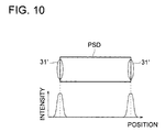
- two illuminating optical systems or two receiving optical systems are disposed at symmetrical positions in respect to a surface perpendicular to the surface of the subject and the generated signals are synthesized or selected, for instance, to cancel the specific noise components.
- both PSD 4a and PSD 4b are disposed in inclined directions at both sides in respect to the illuminating light entering from a perpendicular direction, and the signals outputted from either PSD 4a or PSD 4b are selected to utilize the signals, having no disorder caused by the eclipsing actions, for the arithmetic processing.
- a plurality of photo-receiving elements are symmetrically disposed, and the photo-receiving results of the plurality of photo-receiving elements are synthesized or selected to reduce the noise components caused by the optical factors, and as a result, the influence of the noise components is suppressed. Further, as shown in Fig.
- both LD 9a and LD 9b are disposed in inclined directions at both sides, and PSD 4 detects the light reflected in a perpendicular direction at the center.
- a plurality of light sources are symmetrically disposed to cancel the noise components caused by the optical factors with each of the light, and as a result, the influence of the noise components is suppressed.
- an optical reading method or an optical reading apparatus in which objective information are obtained by optically reading the subject, and then, applying an arithmetic processing to the read results, it becomes possible to reduce the influence of the noise components caused by the optical factors and to improve the accuracy of the necessary information being a detecting object.
Landscapes
- Biochemistry (AREA)
- General Health & Medical Sciences (AREA)
- Signal Processing (AREA)
- Physics & Mathematics (AREA)
- Health & Medical Sciences (AREA)
- Life Sciences & Earth Sciences (AREA)
- Computer Vision & Pattern Recognition (AREA)
- Chemical & Material Sciences (AREA)
- Engineering & Computer Science (AREA)
- Analytical Chemistry (AREA)
- General Physics & Mathematics (AREA)
- Immunology (AREA)
- Pathology (AREA)
- Facsimile Scanning Arrangements (AREA)
- Image Input (AREA)
- Optical Head (AREA)
Abstract
Description
in the optical reading apparatus, which comprises a light source, a photo-receiving element and an arithmetic processing section, and detects information of a subject by opt-electronically converting a reflected light or a transmitted light of the light bundle emitted from the light source in respect to the subject having optical information and by applying an arithmetic processing to opt-electronically converted results, the optical reading apparatus comprises an elimination calculating section for performing an elimination calculating processing as a separate arithmetic processing to be performed before the arithmetic processing to reduce noise components caused by optical factors when the photo-receiving element detects the reflected light or the transmitted light of the light bundle emitted from the light source. For instance, to discriminate and classify papers based on a reflecting rate of each paper in a factory, etc., in which box-type products made of papers are handled, the intensity of the light reflected from the paper, being an inspection subject, could be measured to discriminate and classify papers. The measurement is performed under a room lamp, a fluorescent lamp in the vicinity or an illuminating light source provided with the photo-receiving element, and the signals outputted from the photo-receiving element are analogue-to-digital converted to store them. In this case, when a shadow portion of a box arrives at the detecting position, the intensity of the received light abruptly decreases at the shadow portion, and it is erroneously determined that the box has a very low reflecting rate. To avoid the above drawback, the information lower than a predetermined light intensity is eliminated by performing logical judgments. Thus, it becomes possible to accurately discriminate the subject.Accordingly, in the optical reading apparatus of
in the optical reading method, in which a distribution of deviations of at least one of a convex or a concave, recorded on a subject, is detected by the steps of irradiating a light bundle emitted from a light source onto the surface of the subject, guiding the light reflected from the surface of the subject to a photo-receiving element being capable of detecting a receiving position of the reflected light, and applying an arithmetic processing, for finding a centroid of the reflected light, to the signals photo-electronically converted by the photo-receiving element,
the distribution of deviations of at least one of the convex or the concave, recorded on the subject, is detected by the steps of finding the centroid of the reflected light caused by a distribution of reflecting rates of the subject, and subtracting the centroid of the reflected light caused by a distribution of reflecting rates of the subject from the centroid of the reflected light found from the signals photo-electronically converted by the photo-receiving element.
in the optical reading apparatus, in which a distribution of deviations of at least one of a convex or a concave, recorded on a subject, is detected by the steps of irradiating a light bundle emitted from a light source onto the surface of the subject, guiding the light reflected from the surface of the subject to a photo-receiving element being capable of detecting a receiving position of the reflected light, and applying an arithmetic processing, for finding a centroid of the reflected light, to the signals photo-electronically converted by the photo-receiving element,
the distribution of deviations of at least one of the convex or the concave, recorded on the subject, is detected by the steps of finding the centroid of the reflected light caused by a distribution of reflecting rates of the subject, and subtracting the centroid of the reflected light caused by a distribution of reflecting rates of the subject from the centroid of the reflected light found from the signals photo-electronically converted by the photo-receiving element. Generally speaking, in the operation for optically reading the information with the reflected light, the variation of reflecting rates on the surface of the subject caused by the information, being different from the information of the detecting object, could be the cause of a big confusion in respect to the information of the detecting object. Specifically, when other signals (quasi-signals), the amplitude of which is equivalent to or larger than that of the original signals to be obtained, is outputted from the photo-receiving element in a state of overlapping each other, it is virtually impossible to eliminate the quasi-signals in advance only by its mechanism and/or optical configuration. It becomes possible, however, to reduce the noise components, disturbing as the quasi-signals, by performing the steps of storing the signals outputted from the photo-receiving element into a memory, deriving the information in regard to the variation of reflecting rates on the surface of the subject in an arithmetic processing operation, and removing the information from the signals outputted from the photo-receiving element. Incidentally, the arithmetic processing operation, performed in this case, is a kind of simulation calculating operation.An apparatus, in which the photo-receiving element is a position detecting element, such as the PSD, etc., being capable of detecting the centroid of the received light, the light source is the LD (Laser Diode), the illumination light is a linear light formed by shaping the light bundle emitted from the light source with a cylindrical lens, etc., the subject is a card-type subject, which moves at a constant velocity and comprises at least one of a concave and a convex, and the PSD can receive the linear light corresponding to the convex or the concave projected on the PSD, is assumed as a concrete example. Incidentally, when a one-dimensional PSD is employed for the PSD serving as a photo-receiving element, two electronic currents can be outputted from the both ends of the photo-receiving element. In this case, it is possible to derive the centroid position of the light received on the PSD from the arithmetic processing of the value, obtained through the processes of the I/V conversion, the amplifying operation and the A/D conversion of the two electronic currents. Further, by image-processing the information of the centroid position by means of a processing device such as a computer, etc., and recognizing the information as the convex or the concave, it is possible to distinguish the information of characters, numerals, etc. formed in either the convex or the concave by embossing the subject.In other words, it is possible to obtain the accurate optical information of at least one of the convex or the concave, in which the noise components are reduced, by calculating the centroid position of the light in respect to the noise components, serving as quasi-signals, from the optical information in proportion to the distribution of reflecting rates, and by subtracting the centroid position of the light in respect to the noise components from the information of the centroid position of the light, which is initially found from the light received on the PSD by directly applying the arithmetic processing.
Claims (20)
- An optical reading apparatus, comprising:a light source to irradiate a light flux onto a subject;a photo-receiving element to receive a reflected light or a transmitted light of said light flux irradiated onto said subject, and to generate signals based on an opt-electronic converting action;an arithmetic processing section to apply an arithmetic processing to said signals, in order to detect information of said subject; anda calculating section to apply a calculating processing, for reducing noise components caused by optical factors, to said signals generated by said photo-receiving element, in order to obtain output signals in which noise components are reduced, before said arithmetic processing section applies said arithmetic processing to said signals.
- The optical reading apparatus of claim 1,
wherein said photo-receiving element is capable of detecting a photo-receiving position, and said optical reading apparatus detects a distribution of deviations of at least one of a convex or a concave on said subject, based on the variation of said photo-receiving position. - The optical reading apparatus of claim 2,
wherein said noise components caused by optical factors, arises from a distribution of light-reflecting rates or light-transmitting rates of said subject. - The optical reading apparatus of claim 3,
wherein said calculating section finds a first centroid of the light on said photo-receiving element, and a second centroid of the light on said photo-receiving element, caused by said distribution of light-reflecting rates or light-transmitting rates of said subject, from said signals generated by said photo-receiving element, and said output signals, in which said noise components are reduced, are obtained by applying said calculating processing, for reducing said noise components caused by optical factors, to said signals generated by said photo-receiving element by subtracting said second centroid of the light from said first centroid of the light. - The optical reading apparatus of claim 4,
wherein said calculating section finds said second centroid of the light from a total quantity of the light on said photo-receiving element. - The optical reading apparatus of claim 5,
wherein said photo-receiving element is a one-dimensional PSD (Position Sensitive Detector), and said calculating section finds said first centroid of the light from two electronic current values or two voltage values outputted from both ends of said one-dimensional PSD, and said calculating section finds said second centroid of the light from a sum of two electronic current values or two voltage values outputted from both ends of said one-dimensional PSD. - The optical reading apparatus of claim 6,
wherein said calculating section comprises a memory to store said two electronic current values or said two voltage values outputted from said both ends of said one-dimensional PSD, and said calculating section finds said first centroid of the light from two electronic current values or two voltage values stored in said memory, and said memory also stores said sum of said two electronic current values or said two voltage values, and said calculating section finds said second centroid of the light from said sum stored in said memory. - The optical reading apparatus of claim 6,
wherein said light flux is irradiated onto said subject while said subject is moving relative to said light flux, and said light flux has a width in a moving direction of said subject or said light flux, and the light on said photo-receiving element has a light-spot width corresponding to said width of said light flux, and said calculating section finds said second centroid of the light from said sum of two electronic current values or two voltage values outputted from said both ends of said one-dimensional PSD, in respect to said light-spot width. - The optical reading apparatus of claim 1,
wherein said light flux is irradiated onto said subject while said subject is moving relative to said light flux in a moving direction, and said light flux is a linear light being slender in a direction orthogonal to said moving direction. - The optical reading apparatus of claim 3,
wherein said calculating section finds said noise components caused by optical factors, based on a difference between frequency components of said signals generated by said photo-receiving element. - The optical reading apparatus of claim 1,
wherein said photo-receiving element is either a PSD, a PD (Photo Diode) or a solid-state imager. - The optical reading apparatus of claim 1,
wherein said optical reading apparatus detects a distribution of deviations of at least one of a convex or a concave formed on said subject, and said photo-receiving element is a multi-segmented photo-diode, and either a knife edge method, an astigmatism method or a beam-size method is employed for detecting said distribution of deviations of at least one of a convex or a concave formed on said subject. - The optical reading apparatus of claim 1, further comprising:
an aperture to optically shade said noise components caused by optical factors. - The optical reading apparatus of claim 1,
wherein a plurality of light sources, each of which is equivalent to said light source, are symmetrically disposed to optically reduce said noise components caused by optical factors. - The optical reading apparatus of claim 1,
wherein a plurality of photo-receiving elements, each of which is equivalent to said photo-receiving element, are symmetrically disposed, and photo-receiving results outputted from said photo-receiving elements are synthesized or selected to optically reduce said noise components caused by optical factors. - A method for reading optical information, comprising the steps of:irradiating a light flux onto a subject;receiving a reflected light or a transmitted light of said light flux, irradiated onto said subject, with a photo-receiving element;generating signals based on an opt-electronic converting action performed by said photo-receiving element;applying a calculating processing, for reducing noise components caused by optical factors, to said signals, in order to obtain output signals in which noise components are reduced; andapplying an arithmetic processing to said output signals, in order to detect information of said subject.
- The method of claim 16,
wherein it is possible to detect a photo-receiving position on said photo-receiving element from said signal, and a distribution of deviations of at least one of a convex or a concave on said subject is detected, based on the variation of said photo-receiving position. - The method of claim 17,
wherein said noise components caused by optical factors, arises from a distribution of light-reflecting rates or light-transmitting rates of said subject. - The method of claim 18,
wherein a first centroid of the light on said photo-receiving element, and a second centroid of the light on said photo-receiving element, caused by said distribution of light-reflecting rates or light-transmitting rates of said subject, are found from said signals generated by said photo-receiving element, and said output signals, in which said noise components are reduced, are obtained by applying said calculating processing, for reducing said noise components caused by optical factors, to said signals generated by said photo-receiving element by subtracting said second centroid of the light from said first centroid of the light. - The method of claim 19,
wherein said second centroid of the light is found from a total quantity of the light on said photo-receiving element.
Applications Claiming Priority (2)
| Application Number | Priority Date | Filing Date | Title |
|---|---|---|---|
| JP2000176599 | 2000-06-13 | ||
| JP2000176599 | 2000-06-13 |
Publications (2)
| Publication Number | Publication Date |
|---|---|
| EP1164369A2 true EP1164369A2 (en) | 2001-12-19 |
| EP1164369A3 EP1164369A3 (en) | 2004-02-04 |
Family
ID=18678309
Family Applications (1)
| Application Number | Title | Priority Date | Filing Date |
|---|---|---|---|
| EP01305076A Withdrawn EP1164369A3 (en) | 2000-06-13 | 2001-06-11 | Ootical reading apparatus and optical reading method |
Country Status (2)
| Country | Link |
|---|---|
| US (1) | US6637656B2 (en) |
| EP (1) | EP1164369A3 (en) |
Families Citing this family (4)
| Publication number | Priority date | Publication date | Assignee | Title |
|---|---|---|---|---|
| JP4086523B2 (en) * | 2001-12-04 | 2008-05-14 | キヤノン株式会社 | Image reading apparatus, subject collation system, subject recognition system, and image reading method |
| US7609883B1 (en) | 2005-10-11 | 2009-10-27 | Adobe Systems, Incorporated | Method and apparatus for compensating for uneven lighting in an image |
| US7823782B2 (en) * | 2005-11-22 | 2010-11-02 | Shofu Inc. | Dental optical coherence tomograph |
| US7556200B1 (en) * | 2005-12-22 | 2009-07-07 | Ncr Corporation | Methods and apparatus for reducing the influence of noise in an optical scanning system |
Family Cites Families (9)
| Publication number | Priority date | Publication date | Assignee | Title |
|---|---|---|---|---|
| US3745354A (en) * | 1971-04-23 | 1973-07-10 | American Cyanamid Co | Detector for reading bar codes on moving articles and having improved signal-to-noise ratio |
| US6213399B1 (en) * | 1991-07-25 | 2001-04-10 | Symbol Technologies, Inc. | Multi-channel signal processing in an optical reader |
| US5668887A (en) * | 1992-05-29 | 1997-09-16 | Eastman Kodak Company | Coating density analyzer and method using non-synchronous TDI camera |
| EP0572336B1 (en) * | 1992-05-29 | 2001-03-14 | Eastman Kodak Company | Coating density analyzer and method using image processing |
| EP0742431B1 (en) * | 1995-05-10 | 2000-03-15 | Mahlo GmbH & Co. KG | Method and apparatus for detecting flaws in moving fabrics or the like |
| ATE202865T1 (en) * | 1997-09-17 | 2001-07-15 | Datalogic Spa | DEVICE AND METHOD FOR DETERMINING THE PRESENCE AND EXTENSION OF AN OBJECT |
| EP0921491A1 (en) * | 1997-12-05 | 1999-06-09 | Datalogic S.P.A. | Method of estimating the mid-points of bar code elements" |
| EP0926582B1 (en) * | 1997-12-24 | 2000-09-27 | Datalogic S.P.A. | Apparatus and process for focusing a laser beam for optical codes |
| US6211505B1 (en) * | 1997-12-25 | 2001-04-03 | Nec Corporation | Method and apparatus for checking shape |
-
2001
- 2001-06-11 EP EP01305076A patent/EP1164369A3/en not_active Withdrawn
- 2001-06-12 US US09/878,430 patent/US6637656B2/en not_active Expired - Fee Related
Also Published As
| Publication number | Publication date |
|---|---|
| US20010050313A1 (en) | 2001-12-13 |
| EP1164369A3 (en) | 2004-02-04 |
| US6637656B2 (en) | 2003-10-28 |
Similar Documents
| Publication | Publication Date | Title |
|---|---|---|
| US5270794A (en) | Fine structure evaluation apparatus and method | |
| US6538751B2 (en) | Image capturing apparatus and distance measuring method | |
| KR100914567B1 (en) | Method and apparatus f0r inspecting a pattern | |
| KR100190312B1 (en) | Foreign body inspection device | |
| US20020097404A1 (en) | Distance determination | |
| US4657393A (en) | Pattern optimization when measuring depth to a surface using lens focusing | |
| JP2002283775A (en) | Card authentication device | |
| US6637656B2 (en) | Optical reading apparatus and optical reading method | |
| JP4130236B2 (en) | Object surface shape measuring method and apparatus | |
| JP2022014213A (en) | Flow cytometer, imaging device, method for detecting position, and program | |
| EP3848669B1 (en) | Height measuring device, charged particle beam apparatus, and height measuring method | |
| US7362421B2 (en) | Analysis of signal oscillation patterns | |
| JP3677868B2 (en) | Optical displacement measuring device | |
| JPH0262178B2 (en) | ||
| EP0926485A2 (en) | Method and apparatus for checking shape | |
| CN114942245A (en) | Laser packaging material detection device, system and method | |
| JP2746852B2 (en) | Transmitted light measurement device | |
| US20250044211A1 (en) | Flow cytometer, position calculation method, and program | |
| JP3180019B2 (en) | Document edge detection device | |
| JP7566302B2 (en) | Flow cytometer, method for determining observed object, and program | |
| JPH07151514A (en) | Overlap accuracy measuring method and measuring device | |
| JP2002074355A (en) | Method and device for optical reading | |
| WO2023062831A1 (en) | Flow cytometer, position calculating method, and program | |
| JP4100303B2 (en) | Optical head evaluation method and apparatus | |
| US20040007659A1 (en) | Focus error detection apparatus and method |
Legal Events
| Date | Code | Title | Description |
|---|---|---|---|
| PUAI | Public reference made under article 153(3) epc to a published international application that has entered the european phase |
Free format text: ORIGINAL CODE: 0009012 |
|
| AK | Designated contracting states |
Kind code of ref document: A2 Designated state(s): AT BE CH CY DE DK ES FI FR GB GR IE IT LI LU MC NL PT SE TR |
|
| AX | Request for extension of the european patent |
Free format text: AL;LT;LV;MK;RO;SI |
|
| PUAL | Search report despatched |
Free format text: ORIGINAL CODE: 0009013 |
|
| AK | Designated contracting states |
Kind code of ref document: A3 Designated state(s): AT BE CH CY DE DK ES FI FR GB GR IE IT LI LU MC NL PT SE TR |
|
| AX | Request for extension of the european patent |
Extension state: AL LT LV MK RO SI |
|
| RIC1 | Information provided on ipc code assigned before grant |
Ipc: 7G 01N 21/956 B Ipc: 7G 01N 21/89 B Ipc: 7G 01N 21/55 A |
|
| AKX | Designation fees paid | ||
| REG | Reference to a national code |
Ref country code: DE Ref legal event code: 8566 |
|
| RAP1 | Party data changed (applicant data changed or rights of an application transferred) |
Owner name: KONICA MINOLTA OPTO, INC. |
|
| STAA | Information on the status of an ep patent application or granted ep patent |
Free format text: STATUS: THE APPLICATION IS DEEMED TO BE WITHDRAWN |
|
| 18D | Application deemed to be withdrawn |
Effective date: 20040805 |