EP1164289A2 - Swash plate type compressor - Google Patents
Swash plate type compressor Download PDFInfo
- Publication number
- EP1164289A2 EP1164289A2 EP01114172A EP01114172A EP1164289A2 EP 1164289 A2 EP1164289 A2 EP 1164289A2 EP 01114172 A EP01114172 A EP 01114172A EP 01114172 A EP01114172 A EP 01114172A EP 1164289 A2 EP1164289 A2 EP 1164289A2
- Authority
- EP
- European Patent Office
- Prior art keywords
- drive shaft
- chamber
- end portion
- compressor
- crank chamber
- Prior art date
- Legal status (The legal status is an assumption and is not a legal conclusion. Google has not performed a legal analysis and makes no representation as to the accuracy of the status listed.)
- Withdrawn
Links
- 238000007789 sealing Methods 0.000 claims abstract description 50
- 238000006073 displacement reaction Methods 0.000 claims description 13
- 239000000314 lubricant Substances 0.000 claims description 12
- 238000011144 upstream manufacturing Methods 0.000 claims 1
- 239000003507 refrigerant Substances 0.000 description 38
- 230000006835 compression Effects 0.000 description 16
- 238000007906 compression Methods 0.000 description 16
- 238000006243 chemical reaction Methods 0.000 description 11
- CURLTUGMZLYLDI-UHFFFAOYSA-N Carbon dioxide Chemical compound O=C=O CURLTUGMZLYLDI-UHFFFAOYSA-N 0.000 description 7
- 229910002092 carbon dioxide Inorganic materials 0.000 description 6
- 239000001569 carbon dioxide Substances 0.000 description 6
- 239000003570 air Substances 0.000 description 5
- 238000001816 cooling Methods 0.000 description 5
- 230000006837 decompression Effects 0.000 description 5
- 230000003247 decreasing effect Effects 0.000 description 5
- 239000011347 resin Substances 0.000 description 5
- 229920005989 resin Polymers 0.000 description 5
- 230000005540 biological transmission Effects 0.000 description 4
- KYKAJFCTULSVSH-UHFFFAOYSA-N chloro(fluoro)methane Chemical compound F[C]Cl KYKAJFCTULSVSH-UHFFFAOYSA-N 0.000 description 4
- 229910052751 metal Inorganic materials 0.000 description 4
- 239000002184 metal Substances 0.000 description 4
- XEEYBQQBJWHFJM-UHFFFAOYSA-N Iron Chemical compound [Fe] XEEYBQQBJWHFJM-UHFFFAOYSA-N 0.000 description 2
- 230000007423 decrease Effects 0.000 description 2
- NBVXSUQYWXRMNV-UHFFFAOYSA-N fluoromethane Chemical compound FC NBVXSUQYWXRMNV-UHFFFAOYSA-N 0.000 description 2
- 230000001050 lubricating effect Effects 0.000 description 2
- 238000005461 lubrication Methods 0.000 description 2
- OKTJSMMVPCPJKN-UHFFFAOYSA-N Carbon Chemical compound [C] OKTJSMMVPCPJKN-UHFFFAOYSA-N 0.000 description 1
- 229910052782 aluminium Inorganic materials 0.000 description 1
- XAGFODPZIPBFFR-UHFFFAOYSA-N aluminium Chemical compound [Al] XAGFODPZIPBFFR-UHFFFAOYSA-N 0.000 description 1
- 239000012080 ambient air Substances 0.000 description 1
- 230000000712 assembly Effects 0.000 description 1
- 238000000429 assembly Methods 0.000 description 1
- 229910052799 carbon Inorganic materials 0.000 description 1
- 229910052742 iron Inorganic materials 0.000 description 1
Images



Classifications
-
- F—MECHANICAL ENGINEERING; LIGHTING; HEATING; WEAPONS; BLASTING
- F04—POSITIVE - DISPLACEMENT MACHINES FOR LIQUIDS; PUMPS FOR LIQUIDS OR ELASTIC FLUIDS
- F04B—POSITIVE-DISPLACEMENT MACHINES FOR LIQUIDS; PUMPS
- F04B27/00—Multi-cylinder pumps specially adapted for elastic fluids and characterised by number or arrangement of cylinders
- F04B27/08—Multi-cylinder pumps specially adapted for elastic fluids and characterised by number or arrangement of cylinders having cylinders coaxial with, or parallel or inclined to, main shaft axis
- F04B27/10—Multi-cylinder pumps specially adapted for elastic fluids and characterised by number or arrangement of cylinders having cylinders coaxial with, or parallel or inclined to, main shaft axis having stationary cylinders
- F04B27/1036—Component parts, details, e.g. sealings, lubrication
Definitions
- the present invention relates to a swash plate type compressor that has single headed pistons and is used in an air conditioner of a vehicle, and more particularly, to improvement of a radial bearing that supports a drive shaft for reciprocating the pistons and to improvement of a lubricating structure of a shaft sealing assembly.
- the housing of a typical swash plate type compressor includes a front housing member 71, a cylinder block 72 and a rear housing member 73, which are secured to one another.
- a drive shaft 74 has a first end and a second end.
- the drive shaft 74 is supported by the housing through a first and second radial bearings 75, 76 such that the first end protrudes from the front housing member 71.
- a shaft sealing assembly 78 is located about the drive shaft 74 at a position between the first end and the first radial bearing 75. The sealing assembly 78 prevents refrigerant gas from leaking from a crank chamber 77 to the atmosphere.
- Moving parts of a compressor such as bearings are lubricated by misted lubricant contained in refrigerant gas. Therefore, parts where refrigerant gas is stagnant are not effectively lubricated.
- a compressor that uses carbon dioxide (CO 2 ) for a cooling circuit instead of chlorofluorocarbon has been introduced.
- CO 2 carbon dioxide
- the refrigerant pressure is more than ten times that of a case where chlorofluorocarbon is used as refrigerant, which increases the load acting on bearings and shaft sealing assemblies. Accordingly, lubrication must be improved.
- the shaft sealing assembly 78 is located in an isolated chamber 80, which is forward of the first radial bearing 75.
- a decompression passage 79 is formed in the drive shaft 74.
- An outlet 79b of the decompression passage 79 opens to the end face of the second end of the drive shaft 74.
- a fan 81 is attached to the second end of the drive shaft 74. When the fan 81 rotates integrally with the drive shaft 74, refrigerant in the decompression passage 79 is drawn to the outlet 79b. The refrigerant then flows to the crank chamber 77 through the radial bearing 76.
- the isolated chamber 80 is connected to the crank chamber 77 through the space in the radial bearing 75 and the space in a thrust bearing 82.
- the spaces in the radial bearing 75 and the thrust bearing 82 function as oil supplying passages.
- Japanese Unexamined Patent Publication No. 8-165987 discloses a compressor shown in Fig. 7.
- a second end of the drive shaft 74 faces a chamber 84 that communicates with a suction chamber 83.
- An axial passage 85 is formed in the drive shaft 74.
- the inlet 85a of the passage 85 opens to an isolated chamber 80.
- the outlet 85b of the passage 85 opens to the chamber 84.
- the fan 81 attached to the drive shaft 74 draws some of refrigerant gas into the decompression passage 79 through the first radial bearing 75 or through the thrust bearing 82.
- the drawn refrigerant gas then returns to the crank chamber 77 through the second radial bearing 76. Accordingly, the radial bearings 75, 76 and the shaft sealing assembly 78 are reliably lubricated.
- the fan 81 is required, which complicates the structure.
- the chamber 84 is located adjacent to the second end of the drive shaft 74 of the compressor shown in Fig. 7, and the passage 85 is formed in the drive shaft 74 to connect the isolated chamber 80 with the chamber 84.
- refrigerant flows through the radial bearings 75, 76 or through the thrust bearing 82 in accordance with the pressure difference between the crank chamber 77 and the chamber 84.
- the inlet 85a is located between the shaft sealing assembly 78 and the thrust bearing, flow of refrigerant is weakened either in the shaft sealing assembly 78 or in the thrust bearing, which results in insufficient lubrication.
- a swash plate type compressor that includes a simple structure for effectively lubricating radial bearings, which support a drive shaft, and a shaft sealing assembly.
- a swash plate type compressor includes a housing, a drive shaft, first and second radial bearings, a piston, a cam plate, a shaft sealing assembly.
- a suction chamber, a discharge chamber and a crank chamber are defined in the housing.
- the housing has at least one cylinder bore.
- the drive shaft is rotatably supported by the housing and has a first end portion and a second end portion. The first end portion protrudes from the housing.
- the first and second radial bearings support the first and second end portions of the drive shaft, respectively.
- the piston is reciprocally accommodated in the cylinder bore.
- the cam plate is accommodated in the crank chamber and is operably coupled to the piston to convert rotation of the drive shaft into reciprocation of the piston.
- the shaft sealing assembly seals the space between the drive shaft and the housing and is accommodated in the suction chamber.
- the suction chamber is closer to the first end portion of the drive shaft than the first radial bearing is.
- a passage is formed in the drive shaft to connect the suction chamber to the crank chamber.
- the passage has an inlet and an outlet. The inlet is closer to the second end portion than the second radial bearing is. The outlet is closer to the second end portion than the first radial bearing is.
- the housing 11 of the compressor 10 includes a front housing member 12, a cylinder block 13 and a rear housing member 14, which are arranged in the order of the front housing member 12, the cylinder block 13 and the rear housing member 14 from a first end (left end as viewed in Fig. 1) of the housing 11.
- the front housing member 12, the cylinder block 13 and the rear housing member 14 are secured to one another by bolts (not shown).
- a valve plate assembly 16 is located between the front housing member 12 and the cylinder block 13.
- a crank chamber 17 is defined between the cylinder block 13 and the rear housing member 14.
- a drive shaft 18 extends through a hole formed in the valve plate assembly 16.
- the drive shaft 18 is rotatably supported by the housing 11 such that a first end of the drive shaft 18 protrudes from the front housing member 12 and a second end is located in the crank chamber 17.
- a suction pressure zone which is a suction chamber 19 in this embodiment, is defined in the front housing member 12.
- the suction chamber 19 is located in the vicinity of the first end of the drive shaft 18.
- a discharge chamber 20 is defined in the front housing member 12 and surrounds the suction chamber 19.
- a ring recess 21 is formed in the front housing member 12.
- the ring recess 21 opens to the suction chamber 19 and faces the valve plate assembly 16.
- a shaft hole 22 is formed in the cylinder block 13 to communicate the crank chamber 17 with the suction chamber 19.
- a bearing recess 23 is formed in the rear housing member 14. The bearing recess 23 opens to the crank chamber 17 and forms part of the crank chamber 17.
- the drive shaft 18 extends through the shaft hole 22, the suction chamber 19, the ring recess 21 and a through hole formed in the front housing member 12.
- the middle portion of the drive shaft 18 is rotatably supported by the cylinder block 13 through a first radial bearing 24, which is located in the shaft hole 22.
- the second end of the drive shaft 18 is rotatably supported by the rear housing member 14 through a second radial bearing 25, which is located in the recess 23.
- the sealing assembly 26 includes a stationary ring 27, which is fitted in the recess 21, and a carbon sliding ring 29, which is fixed to the drive shaft 18 through an O-ring 28.
- the sliding ring 29 rotates integrally with the drive shaft 18 and slides along the stationary ring 27.
- the stationary ring 27 is loosely fitted to the drive shaft 18, and an O-ring 30 is located between the stationary ring 27 and the front housing member 12.
- a circumferential groove 29a is formed in the outer surface of the sliding ring 29.
- the sealing assembly 26 also includes a support ring 31, which rotates integrally with the drive shaft 18.
- the support ring 31 includes an engaging portion 31a, which is engaged with the groove 29a of the support ring 31.
- the support ring 31 also includes a spring 32, which urges the sliding ring 29 toward the stationary ring 27.
- the space between the drive shaft 18 and the housing 11 is sealed by the O-ring 28, the sliding ring 29, the stationary ring 27 and the O-ring 30.
- Cylinder bores 33 are formed in the cylinder block 13 about the drive shaft 18.
- the cylinder bores 33 are arranged at equal angular intervals about the drive shaft 18. That is, the cylinder bores 33 are formed in the housing 11 between the crank chamber 17 and the valve plate assembly 16.
- a single-headed piston 34 is housed in each cylinder bore 33. The front and rear openings of each cylinder bore 33 is blocked by the valve plate assembly 16 and the corresponding piston 34, respectively.
- Each piston 34 and the corresponding cylinder bore 33 define a compression chamber 35, the volume of which is changed according to reciprocation of the piston 34.
- a rotating support which is a lug plate 36 in this embodiment, is secured to the drive shaft 18 in the vicinity of the second end of the drive shaft 18.
- the lug plate 36 rotates integrally with the drive shaft 18.
- the lug plate 36 is received by the rear housing member 14 through a first thrust bearing 37.
- An inner wall 14a receives the axial load generated by compression reaction force of the pistons 34 and functions as a restriction surface that defines the axial position of the drive shaft 18.
- a cam plate which is a swash plate 38 in this embodiment, is located in the crank chamber 17.
- a through hole 38a is formed in the swash plate 38 and the drive shaft 18 extends through the hole 38a.
- a hinge mechanism 39 is located between the lug plate 36 and the swash plate 38.
- the hinge mechanism 39 includes two support arms 40 (only one is shown) and two guide pins 42 (only one is shown). Each support arm 40 projects from the front side of the lug plate 36.
- a guide hole 41 is formed in each support arm 40.
- Each guide pin 42 includes a spherical portion 42a, which is engaged with the corresponding guide hole 41.
- the hinge mechanism 39 permits the swash plate 38 to rotate integrally with the lug plate 36 and the drive shaft 18.
- the hinge mechanism 39 also permits the swash plate 38 to slide along the drive shaft 18 and to tilt with respect to the axis of the drive shaft 18.
- the lug plate 36 and the hinge mechanism 39 form an inclination angle control means.
- the swash plate 38 has a counterweight 38b located at the opposite side of the drive shaft 18 from the hinge mechanism 39.
- a snap ring 43 is fixed to the drive shaft 18.
- the snap ring 43 is located in a large diameter portion 22a of the shaft hole 22.
- a second thrust bearing 44 is fitted to the drive shaft 18 and is located in the large diameter portion 22a.
- a first coil spring 45 is fitted about the drive shaft 18 and extends between the snap ring 43 and the second thrust bearing 44. The first coil spring 45 urges the drive shaft 18 toward the restriction surface (the inner wall surface 14a of the rear housing member 14) at least when the compressor 10 is not running.
- a second coil spring 46 is fitted about the drive shaft 18 between the lug plate 36 and the swash plate 38.
- the second coil spring 46 urges the swash plate 38 toward the cylinder block 13, or in the direction decreasing the inclination angle.
- a restoring spring which is a third coil spring 47 in this embodiment, is fitted about the drive shaft 18 between the swash plate 38 and the snap ring 43.
- the coil spring 47 remains at the normal length and applies no force to the swash plate 38.
- the third coil spring 47 is compressed between the swash plate 38 and the snap ring 43 and urges the swash plate 38 away from the cylinder block 13, or in the direction increasing the inclination angle, by a force that corresponds to the compression amount.
- Each piston 34 is coupled to the circumferential portion of the swash plate 38 through a pair of shoes 48.
- the swash plate 38 and the shoes 48 are made of iron-based metal. Sliding portions of the swash plate 38 and the shoes 48 are treated to prevent seizing. For example, an aluminum-based metal is thermal sprayed or friction welded onto the sliding portions of the swash plate 38 and the shoes 48.
- the drive shaft 18 is coupled to an engine 50 by a power transmission mechanism 49.
- the power transmission mechanism 49 is a clutchless mechanism that includes, for example, a belt and a pulley.
- the power transmission mechanism 49 therefore constantly transmits power from the engine 50 to the compressor when the engine 50 is running.
- the mechanism 49 may be a clutch mechanism (for example, an electromagnetic clutch) that selectively transmits power when supplied with a current.
- the valve plate assembly 16 has suction ports 51 and discharge ports 53, which correspond to each cylinder bore 33.
- the valve plate assembly 16 also has suction valve flaps 52, each of which corresponds to one of the suction ports 51, and discharge valve flaps 54, each of which corresponds to one of the discharge ports 53.
- Each cylinder bore 33 is connected to the suction chamber 19 through the corresponding suction port 51 and is connected to the discharge chamber 20 through the corresponding discharge port 53.
- a supply passage 55 is formed in the cylinder block 13 and the rear housing member 14 to connect the crank chamber 17 with the discharge chamber 20.
- a control valve 56 regulates the supply passage 55 to control the inclination angle of the swash plate 38.
- the outlet 55a of the supply passage 55 is located above the first thrust bearing 37.
- the control valve 56 is a conventional electromagnetic valve.
- the valve chamber of the control valve 56 is located in the supply passage 55. When the solenoid of the control valve 56 is excited, the control valve 56 opens the supply passage 55. When the solenoid is de-excited, the control valve 56 closes the supply passage 55. The opening amount of the supply passage 55 is controlled in accordance with the level of the supplied current.
- the suction chamber 19 is connected to the discharge chamber 20 through an external refrigerant circuit 57.
- the refrigerant circuit 57 and the compressor 10 form the cooling circuit of a vehicle air conditioner.
- an axial passage 60 is formed in the drive shaft 18.
- the axial passage 60 forms part of a bleed passage, which connects the suction chamber 19 with the crank chamber 17.
- the inlet 60a of the axial passage 60 is closer to the second end than the second radial bearing 25 is.
- the outlet 60b of the axial passage 60 is closer to the second end than the first radial bearing 24 is.
- a fixed restrictor 61 is located in the axial passage 60.
- the restrictor 61 is formed by fitting a plug that has a small through hole into the axial passage 60.
- a filter 62 is fixed to the second end of the drive shaft 18 to rotate integrally with the drive shaft 18.
- the filter 62 covers the inlet 60a of the axial passage 60.
- the filter 62 is made, for example, of a mesh, a plate having many holes or a porous plate.
- a seal ring 63 is located in the shaft hole 22 between the outer surface of the drive shaft 18 and the inner wall of the cylinder block 13.
- the seal ring 63 is located between the outlet 60b and the second thrust bearing 44.
- the seal ring 63 prevents refrigerant in the crank chamber 17 from leaking to the suction chamber 19 through the shaft hole 22.
- the seal ring 63 is made, for example, of rubber or fluorocarbon resin.
- the cross section of the seal ring 63 is U-shaped.
- the lug plate 36 and the hinge mechanism 39 permit the swash plate 38 to rotate integrally with the drive shaft 18. Rotation of the swash plate 38 is converted into reciprocation of each piston 34 by the corresponding shoes 48. As a result, suction, compression and discharge of refrigerant gas are repeated in the compression chambers 35. Refrigerant supplied from the external refrigerant circuit 57 to the suction chamber 19 is drawn into each compression chamber 35 through the corresponding suction port 51. The refrigerant is then compressed by the corresponding piston 34 and is discharged to the discharge chamber 20 through the corresponding discharge port 53. Subsequently, the refrigerant is then sent to the external refrigerant circuit 57 through a discharge passage.
- a controller (not shown) adjusts the opening amount of the control valve 56, or the opening amount of the supply passage 55, to alter the communicating state between the discharge chamber 20 and the crank chamber 17.
- the opening amount of the supply passage 55 is decreased to decrease the flow rate of refrigerant gas from the discharge chamber 20 to the crank chamber 17. Accordingly, the pressure in the crank chamber 17 is gradually lowered due to gas flow from the crank chamber 17 to the suction chamber 19 through the axial passage 60. As a result, the difference between the pressure in the crank chamber 17 and the pressure in the cylinder bores 33 via the pistons 34 decreases, which maximizes the inclination angle of the swash plate 38. Accordingly, the stroke of each piston 34 is increased and the compressor displacement is increased.
- the opening amount of the control valve 56 is increased so that flow rate of refrigerant from the discharge chamber 20 to the crank chamber 17 is increased.
- the pressure in the crank chamber 17 is gradually raised.
- the pressure difference between the crank chamber 17 and the cylinder bores 33 via the pistons 34 increases, which minimizes the inclination angle of the swash plate 38. Therefore, the stroke of each piston 34 is decreased and the displacement of the compressor is decreased.
- the compression reaction force F1 (not shown) of the piston 34 acts on the drive shaft 18 through the corresponding shoes 48, the hinge mechanism 39 and the lug plate 36 and urges the drive shaft 18 toward the rear housing member 14.
- the second end of the drive shaft 18 receives the pressure Pc (not shown), the direction of which is opposite to that of the compression reaction force F1.
- the first end receives the atmospheric pressure Pa (not shown), the direction of which is the same as the compression reaction force F1.
- the element S represents the cross-sectional area of a part of the drive shaft 18 in the crank chamber 17 that corresponds to the seal ring 63.
- the direction of the force F2 is the same as the direction of the compression reaction force F1.
- the force F2 acts in the opposite direction from the direction of the compression reaction force F1. Accordingly, the power required to drive the drive shaft 18 is reduced.
- the power transmission mechanism 49 is clutchless type
- rotation of the engine 50 is transmitted to the drive shaft 18 when the air conditioner is not operating.
- the swash plate 38 is kept at the minimum inclination position, and the pistons 34 compress refrigerant.
- the drive shaft 18 receives the compression reaction force F1.
- the force F2 which is based on the difference between the crank pressure Pc and the atmospheric pressure Pa acts on the drive shaft 18 against the compression reaction force F1. Accordingly, power consumption when the air conditioner is not operating is reduced
- the crank chamber 17 is connected to the suction chamber 19 by the axial passage 60, which is formed in the drive shaft 18, and the seal ring 63 is located adjacent to the outlet 60b of the axial passage 60 and at the side closer the crank chamber 17. Therefore, the path that connects the crank chamber 17 to the suction chamber 19 passes through the space in the first thrust bearing 37, the space between the lug plate 36 and the inner wall of the rear housing member 14, the space in the radial bearing 25, the recess 23, the axial passage 60 and the space in the first radial bearing 24.
- the sealing assembly 26 is reliably lubricated.
- a chamber 64 may be defined by a wall 65 and be located radially inside the suction chamber 19.
- the chamber 64 functions as a suction pressure zone that accommodates the sealing assembly 26, and the suction chamber 19 is connected to the chamber 64 through a hole 65a.
- the second embodiment has the substantially the same advantages as the first embodiment.
- the suction chamber 19 may be radially outside of the discharge chamber 20.
- the suction chamber 19 and the discharge chamber 20 may be located in the rear housing member 14, that is, the suction chamber 19 and the discharge chamber 20 may be located at a side opposite to the protruding portion of the drive shaft 18.
- the chamber 64 which functions as a suction pressure zone, is connected to the suction chamber 19 through a passage (not shown).
- the passage may be a pipe that is located outside the housing or may be formed in the housing.
- the restrictor 61 of the bleed passage 60 may be omitted and the diameter of the bleed passage 60 may be constant.
- the present invention may be embodied in a fixed displacement compressor.
- the present invention may be adapted to a wobble plate type compressor.
- the swash plate 38 which rotates integrally with the drive shaft 18, is replaced with a wobble plate.
- the wobble plate rotates with respect to the drive shaft 18.
- a lip seal 67 includes a metal body 67a, a resin lip ring 67b and a rubber lip ring 67c.
- the resin lip ring 67b and the rubber lip ring 67c are held by the metal body 67a.
- the resin lip ring 67b is made of, for example, a fluorocarbon resin.
- the multiple lip rings 67b, 67c improve the sealing characteristics.
- a helical groove 67d is formed on a surface of the lip ring 67b that slides on the drive shaft 18.
- the helical groove 67d is located about the axis of the drive shaft 18. Relative rotation of the groove 67d with the drive shaft 18 guides lubricant into the suction chamber 19, which further improves the oil sealing characteristics of the lip seal 67.
- the control valve 56 which controls the opening size of the control passage, need not be an electromagnetic control valve.
- an internally controlled valve like the control valve disclosed in Japanese Unexamined Patent Publication No. 6-123281 may be used.
- This valve has a diaphragm, which detects the suction pressure and is displaced accordingly, and a valve mechanism that controls the opening size of the control passage by a displacement of the diaphragm.
- an electromagnetic valve which can be externally controlled, is preferably used.
- the power source of the compressor is not limited to the engine 50.
- the compressor may be driven by an electric motor.
- the present invention may be applied to an electric vehicle.
- a helical groove 63a is formed in a part of the seal ring 63 that slides on the drive shaft 18.
- the helical groove 63a returns lubricant to the crank chamber 17 as the drive shaft 18 rotates.
- lubricant located between the seal ring 63 and the drive shaft 18 is returned to the crank chamber 17.
- excessive amount of lubricant is not supplied to the suction chamber 19, which prevents lubricant from leaking outside of the housing 11 from the sealing assembly 26.
- a helical groove may be formed in the drive shaft 18. In this case, the same advantages as the case of the helical groove 63a are obtained.
- a shaft sealing assembly (26) is located in a suction chamber (19) of a swash plate type compressor to seal the space between a drive shaft (18) and a housing.
- a first end portion of the drive shaft (18) is supported by a first radial bearing (24).
- a second end portion of the drive shaft (18) is supported by a second radial bearing.
- the suction chamber (19) is closer to the first end portion of the drive shaft (18) than the first radial bearing (24) is.
- An axial passage (60) is formed in the drive shaft (18) to connect the suction chamber (19) to the crank chamber (17).
- An inlet (60a) of the axial passage (60) is closer to the second end portion than the second radial bearing is.
- An outlet (60b) of the axial passage (60) is closer to the second end portion than the first radial bearing (24) is.
Landscapes
- Engineering & Computer Science (AREA)
- Mechanical Engineering (AREA)
- General Engineering & Computer Science (AREA)
- Compressors, Vaccum Pumps And Other Relevant Systems (AREA)
Abstract
Description
- The present invention relates to a swash plate type compressor that has single headed pistons and is used in an air conditioner of a vehicle, and more particularly, to improvement of a radial bearing that supports a drive shaft for reciprocating the pistons and to improvement of a lubricating structure of a shaft sealing assembly.
- As shown in Fig. 6, the housing of a typical swash plate type compressor includes a
front housing member 71, acylinder block 72 and arear housing member 73, which are secured to one another. Adrive shaft 74 has a first end and a second end. Thedrive shaft 74 is supported by the housing through a first and secondradial bearings 75, 76 such that the first end protrudes from thefront housing member 71. Ashaft sealing assembly 78 is located about thedrive shaft 74 at a position between the first end and the first radial bearing 75. Thesealing assembly 78 prevents refrigerant gas from leaking from acrank chamber 77 to the atmosphere. - Moving parts of a compressor such as bearings are lubricated by misted lubricant contained in refrigerant gas. Therefore, parts where refrigerant gas is stagnant are not effectively lubricated. A compressor that uses carbon dioxide (CO2) for a cooling circuit instead of chlorofluorocarbon has been introduced. When using CO2 as refrigerant, the refrigerant pressure is more than ten times that of a case where chlorofluorocarbon is used as refrigerant, which increases the load acting on bearings and shaft sealing assemblies. Accordingly, lubrication must be improved.
- In the compressor of Japanese Unexamined Patent Publication No. 11-241681, the
shaft sealing assembly 78 is located in anisolated chamber 80, which is forward of the first radial bearing 75. Adecompression passage 79 is formed in thedrive shaft 74. Anoutlet 79b of thedecompression passage 79 opens to the end face of the second end of thedrive shaft 74. Afan 81 is attached to the second end of thedrive shaft 74. When thefan 81 rotates integrally with thedrive shaft 74, refrigerant in thedecompression passage 79 is drawn to theoutlet 79b. The refrigerant then flows to thecrank chamber 77 through the radial bearing 76. - The
isolated chamber 80 is connected to thecrank chamber 77 through the space in the radial bearing 75 and the space in a thrust bearing 82. The spaces in the radial bearing 75 and the thrust bearing 82 function as oil supplying passages. - Japanese Unexamined Patent Publication No. 8-165987 discloses a compressor shown in Fig. 7. In this compressor, a second end of the
drive shaft 74 faces a chamber 84 that communicates with asuction chamber 83. Anaxial passage 85 is formed in thedrive shaft 74. Theinlet 85a of thepassage 85 opens to anisolated chamber 80. The outlet 85b of thepassage 85 opens to the chamber 84. - In the compressor of Fig. 6, the
fan 81 attached to thedrive shaft 74 draws some of refrigerant gas into thedecompression passage 79 through the first radial bearing 75 or through the thrust bearing 82. The drawn refrigerant gas then returns to thecrank chamber 77 through the second radial bearing 76. Accordingly, theradial bearings 75, 76 and theshaft sealing assembly 78 are reliably lubricated. However, to flow lubricant through thedecompression passage 79, thefan 81 is required, which complicates the structure. - Instead of a fan, the chamber 84 is located adjacent to the second end of the
drive shaft 74 of the compressor shown in Fig. 7, and thepassage 85 is formed in thedrive shaft 74 to connect theisolated chamber 80 with the chamber 84. Thus, refrigerant flows through theradial bearings 75, 76 or through the thrust bearing 82 in accordance with the pressure difference between thecrank chamber 77 and the chamber 84. However, since theinlet 85a is located between theshaft sealing assembly 78 and the thrust bearing, flow of refrigerant is weakened either in theshaft sealing assembly 78 or in the thrust bearing, which results in insufficient lubrication. - Accordingly, it is an objective of the present invention to provide a swash plate type compressor that includes a simple structure for effectively lubricating radial bearings, which support a drive shaft, and a shaft sealing assembly.
- To achieve the foregoing and other objectives and in accordance with the purpose of the present invention, a swash plate type compressor is provided. The compressor includes a housing, a drive shaft, first and second radial bearings, a piston, a cam plate, a shaft sealing assembly. A suction chamber, a discharge chamber and a crank chamber are defined in the housing. The housing has at least one cylinder bore. The drive shaft is rotatably supported by the housing and has a first end portion and a second end portion. The first end portion protrudes from the housing. The first and second radial bearings support the first and second end portions of the drive shaft, respectively. The piston is reciprocally accommodated in the cylinder bore. The cam plate is accommodated in the crank chamber and is operably coupled to the piston to convert rotation of the drive shaft into reciprocation of the piston. The shaft sealing assembly seals the space between the drive shaft and the housing and is accommodated in the suction chamber. The suction chamber is closer to the first end portion of the drive shaft than the first radial bearing is. A passage is formed in the drive shaft to connect the suction chamber to the crank chamber. The passage has an inlet and an outlet. The inlet is closer to the second end portion than the second radial bearing is. The outlet is closer to the second end portion than the first radial bearing is.
- Other aspects and advantages of the invention will become apparent from the following description, taken in conjunction with the accompanying drawings, illustrating by way of example the principles of the invention.
- The invention, together with objects and advantages thereof, may best be understood by reference to the following description of the presently preferred embodiments together with the accompanying drawings in which:
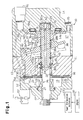
- Fig. 1 is a cross-sectional view illustrating a compressor according to a first embodiment of the present invention;
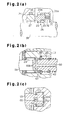
- Fig. 2(a) is an enlarged partial cross-sectional view illustrating the shaft sealing mechanism of the compressor shown in Fig. 1;
- Fig. 2(b) is an enlarged partial cross-sectional view illustrating the outlet of the axial passage of the compressor shown in Fig. 1;
- Fig. 2(c) is an enlarged partial cross-sectional view illustrating a second end of the drive shaft of the compressor shown in Fig. 1;
- Fig. 3 is a partial cross-sectional view illustrating a compressor according to a second embodiment;
- Fig. 4 is a cross-sectional view illustrating a compressor according to a third embodiment;
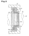
- Fig. 5 is an enlarged partial cross-sectional view illustrating a shaft sealing assembly according to a fourth embodiment;
- Fig. 6 is a cross-sectional view illustrating a prior art compressor;
- Fig. 7 is a cross-sectional view illustrating another prior art compressor; and
- Fig. 8 is an enlarged partial cross-sectional view illustrating a compressor according to a fifth embodiment.
-
- A
variable displacement compressor 10 for vehicle air conditioner according to a first embodiment of the present invention will now be described with reference to Figs. 1 and 2. As shown in Fig. 1, thehousing 11 of thecompressor 10 includes afront housing member 12, acylinder block 13 and arear housing member 14, which are arranged in the order of thefront housing member 12, thecylinder block 13 and therear housing member 14 from a first end (left end as viewed in Fig. 1) of thehousing 11. Thefront housing member 12, thecylinder block 13 and therear housing member 14 are secured to one another by bolts (not shown). Avalve plate assembly 16 is located between thefront housing member 12 and thecylinder block 13. Acrank chamber 17 is defined between thecylinder block 13 and therear housing member 14. - A
drive shaft 18 extends through a hole formed in thevalve plate assembly 16. Thedrive shaft 18 is rotatably supported by thehousing 11 such that a first end of thedrive shaft 18 protrudes from thefront housing member 12 and a second end is located in thecrank chamber 17. A suction pressure zone, which is asuction chamber 19 in this embodiment, is defined in thefront housing member 12. Thesuction chamber 19 is located in the vicinity of the first end of thedrive shaft 18. Adischarge chamber 20 is defined in thefront housing member 12 and surrounds thesuction chamber 19. Aring recess 21 is formed in thefront housing member 12. Thering recess 21 opens to thesuction chamber 19 and faces thevalve plate assembly 16. Ashaft hole 22 is formed in thecylinder block 13 to communicate thecrank chamber 17 with thesuction chamber 19. A bearingrecess 23 is formed in therear housing member 14. The bearingrecess 23 opens to the crankchamber 17 and forms part of thecrank chamber 17. - The
drive shaft 18 extends through theshaft hole 22, thesuction chamber 19, thering recess 21 and a through hole formed in thefront housing member 12. The middle portion of thedrive shaft 18 is rotatably supported by thecylinder block 13 through a firstradial bearing 24, which is located in theshaft hole 22. The second end of thedrive shaft 18 is rotatably supported by therear housing member 14 through a secondradial bearing 25, which is located in therecess 23. - A sealing
assembly 26, which is a mechanical seal, is located in thesuction chamber 19. As shown in Fig. 2(a), the sealingassembly 26 includes astationary ring 27, which is fitted in therecess 21, and acarbon sliding ring 29, which is fixed to thedrive shaft 18 through an O-ring 28. The slidingring 29 rotates integrally with thedrive shaft 18 and slides along thestationary ring 27. Thestationary ring 27 is loosely fitted to thedrive shaft 18, and an O-ring 30 is located between thestationary ring 27 and thefront housing member 12. Acircumferential groove 29a is formed in the outer surface of the slidingring 29. The sealingassembly 26 also includes asupport ring 31, which rotates integrally with thedrive shaft 18. Thesupport ring 31 includes an engagingportion 31a, which is engaged with thegroove 29a of thesupport ring 31. Thesupport ring 31 also includes aspring 32, which urges the slidingring 29 toward thestationary ring 27. The space between thedrive shaft 18 and thehousing 11 is sealed by the O-ring 28, the slidingring 29, thestationary ring 27 and the O-ring 30. - Cylinder bores 33 (only one shown) are formed in the
cylinder block 13 about thedrive shaft 18. The cylinder bores 33 are arranged at equal angular intervals about thedrive shaft 18. That is, the cylinder bores 33 are formed in thehousing 11 between thecrank chamber 17 and thevalve plate assembly 16. A single-headedpiston 34 is housed in each cylinder bore 33. The front and rear openings of each cylinder bore 33 is blocked by thevalve plate assembly 16 and thecorresponding piston 34, respectively. Eachpiston 34 and the corresponding cylinder bore 33 define acompression chamber 35, the volume of which is changed according to reciprocation of thepiston 34. - A rotating support, which is a
lug plate 36 in this embodiment, is secured to thedrive shaft 18 in the vicinity of the second end of thedrive shaft 18. Thelug plate 36 rotates integrally with thedrive shaft 18. Thelug plate 36 is received by therear housing member 14 through afirst thrust bearing 37. Aninner wall 14a receives the axial load generated by compression reaction force of thepistons 34 and functions as a restriction surface that defines the axial position of thedrive shaft 18. - A cam plate, which is a
swash plate 38 in this embodiment, is located in thecrank chamber 17. A throughhole 38a is formed in theswash plate 38 and thedrive shaft 18 extends through thehole 38a. A hinge mechanism 39 is located between thelug plate 36 and theswash plate 38. The hinge mechanism 39 includes two support arms 40 (only one is shown) and two guide pins 42 (only one is shown). Eachsupport arm 40 projects from the front side of thelug plate 36. Aguide hole 41 is formed in eachsupport arm 40. Each guide pin 42 includes a spherical portion 42a, which is engaged with thecorresponding guide hole 41. The hinge mechanism 39 permits theswash plate 38 to rotate integrally with thelug plate 36 and thedrive shaft 18. The hinge mechanism 39 also permits theswash plate 38 to slide along thedrive shaft 18 and to tilt with respect to the axis of thedrive shaft 18. Thelug plate 36 and the hinge mechanism 39 form an inclination angle control means. Theswash plate 38 has acounterweight 38b located at the opposite side of thedrive shaft 18 from the hinge mechanism 39. - A
snap ring 43 is fixed to thedrive shaft 18. Thesnap ring 43 is located in alarge diameter portion 22a of theshaft hole 22. A second thrust bearing 44 is fitted to thedrive shaft 18 and is located in thelarge diameter portion 22a. Afirst coil spring 45 is fitted about thedrive shaft 18 and extends between thesnap ring 43 and the second thrust bearing 44. Thefirst coil spring 45 urges thedrive shaft 18 toward the restriction surface (theinner wall surface 14a of the rear housing member 14) at least when thecompressor 10 is not running. - A
second coil spring 46 is fitted about thedrive shaft 18 between thelug plate 36 and theswash plate 38. Thesecond coil spring 46 urges theswash plate 38 toward thecylinder block 13, or in the direction decreasing the inclination angle. - A restoring spring, which is a third coil spring 47 in this embodiment, is fitted about the
drive shaft 18 between theswash plate 38 and thesnap ring 43. When theswash plate 38 at a large inclination position (the position illustrated by solid lines in Fig. 1), the coil spring 47 remains at the normal length and applies no force to theswash plate 38. When theswash plate 38 is at a small inclination position as illustrated by broken lines, the third coil spring 47 is compressed between theswash plate 38 and thesnap ring 43 and urges theswash plate 38 away from thecylinder block 13, or in the direction increasing the inclination angle, by a force that corresponds to the compression amount. - Each
piston 34 is coupled to the circumferential portion of theswash plate 38 through a pair ofshoes 48. When theswash plate 38 rotates integrally with thedrive shaft 18, rotation is converted into reciprocation of eachpiston 34 by the corresponding shoes 48. Theswash plate 38 and theshoes 48 are made of iron-based metal. Sliding portions of theswash plate 38 and theshoes 48 are treated to prevent seizing. For example, an aluminum-based metal is thermal sprayed or friction welded onto the sliding portions of theswash plate 38 and theshoes 48. - The
drive shaft 18 is coupled to anengine 50 by apower transmission mechanism 49. In this embodiment, thepower transmission mechanism 49 is a clutchless mechanism that includes, for example, a belt and a pulley. Thepower transmission mechanism 49 therefore constantly transmits power from theengine 50 to the compressor when theengine 50 is running. Alternatively, themechanism 49 may be a clutch mechanism (for example, an electromagnetic clutch) that selectively transmits power when supplied with a current. - The
valve plate assembly 16 hassuction ports 51 anddischarge ports 53, which correspond to each cylinder bore 33. Thevalve plate assembly 16 also has suction valve flaps 52, each of which corresponds to one of thesuction ports 51, and discharge valve flaps 54, each of which corresponds to one of thedischarge ports 53. Each cylinder bore 33 is connected to thesuction chamber 19 through the correspondingsuction port 51 and is connected to thedischarge chamber 20 through thecorresponding discharge port 53. - A
supply passage 55 is formed in thecylinder block 13 and therear housing member 14 to connect thecrank chamber 17 with thedischarge chamber 20. Acontrol valve 56 regulates thesupply passage 55 to control the inclination angle of theswash plate 38. Theoutlet 55a of thesupply passage 55 is located above thefirst thrust bearing 37. Thecontrol valve 56 is a conventional electromagnetic valve. The valve chamber of thecontrol valve 56 is located in thesupply passage 55. When the solenoid of thecontrol valve 56 is excited, thecontrol valve 56 opens thesupply passage 55. When the solenoid is de-excited, thecontrol valve 56 closes thesupply passage 55. The opening amount of thesupply passage 55 is controlled in accordance with the level of the supplied current. - The
suction chamber 19 is connected to thedischarge chamber 20 through an externalrefrigerant circuit 57. Therefrigerant circuit 57 and thecompressor 10 form the cooling circuit of a vehicle air conditioner. - As shown in Figs. 1, 2(b) and 2(c), an
axial passage 60 is formed in thedrive shaft 18. Theaxial passage 60 forms part of a bleed passage, which connects thesuction chamber 19 with thecrank chamber 17. Theinlet 60a of theaxial passage 60 is closer to the second end than the secondradial bearing 25 is. Theoutlet 60b of theaxial passage 60 is closer to the second end than the firstradial bearing 24 is. A fixedrestrictor 61 is located in theaxial passage 60. The restrictor 61 is formed by fitting a plug that has a small through hole into theaxial passage 60. - A
filter 62 is fixed to the second end of thedrive shaft 18 to rotate integrally with thedrive shaft 18. Thefilter 62 covers theinlet 60a of theaxial passage 60. Thefilter 62 is made, for example, of a mesh, a plate having many holes or a porous plate. - A
seal ring 63 is located in theshaft hole 22 between the outer surface of thedrive shaft 18 and the inner wall of thecylinder block 13. Theseal ring 63 is located between theoutlet 60b and the second thrust bearing 44. Theseal ring 63 prevents refrigerant in thecrank chamber 17 from leaking to thesuction chamber 19 through theshaft hole 22. Theseal ring 63 is made, for example, of rubber or fluorocarbon resin. The cross section of theseal ring 63 is U-shaped. - The operation of the
compressor 10 will now be described. - As the
drive shaft 18 rotates, thelug plate 36 and the hinge mechanism 39 permit theswash plate 38 to rotate integrally with thedrive shaft 18. Rotation of theswash plate 38 is converted into reciprocation of eachpiston 34 by the corresponding shoes 48. As a result, suction, compression and discharge of refrigerant gas are repeated in thecompression chambers 35. Refrigerant supplied from the externalrefrigerant circuit 57 to thesuction chamber 19 is drawn into eachcompression chamber 35 through the correspondingsuction port 51. The refrigerant is then compressed by the correspondingpiston 34 and is discharged to thedischarge chamber 20 through thecorresponding discharge port 53. Subsequently, the refrigerant is then sent to the externalrefrigerant circuit 57 through a discharge passage. - In accordance with the cooling load, a controller (not shown) adjusts the opening amount of the
control valve 56, or the opening amount of thesupply passage 55, to alter the communicating state between thedischarge chamber 20 and thecrank chamber 17. - When the cooling load is great, the opening amount of the
supply passage 55 is decreased to decrease the flow rate of refrigerant gas from thedischarge chamber 20 to the crankchamber 17. Accordingly, the pressure in thecrank chamber 17 is gradually lowered due to gas flow from thecrank chamber 17 to thesuction chamber 19 through theaxial passage 60. As a result, the difference between the pressure in thecrank chamber 17 and the pressure in the cylinder bores 33 via thepistons 34 decreases, which maximizes the inclination angle of theswash plate 38. Accordingly, the stroke of eachpiston 34 is increased and the compressor displacement is increased. - When the cooling load is decreased, the opening amount of the
control valve 56 is increased so that flow rate of refrigerant from thedischarge chamber 20 to the crankchamber 17 is increased. When the flow rate of refrigerant supplied to the crankchamber 17 surpasses the flow rate of refrigerant that flows out from thecrank chamber 17 to thesuction chamber 19 through theaxial passage 60, the pressure in thecrank chamber 17 is gradually raised. As a result, the pressure difference between thecrank chamber 17 and the cylinder bores 33 via thepistons 34 increases, which minimizes the inclination angle of theswash plate 38. Therefore, the stroke of eachpiston 34 is decreased and the displacement of the compressor is decreased. - When each
piston 34 compresses refrigerant gas, the compression reaction force F1 (not shown) of thepiston 34 acts on thedrive shaft 18 through the correspondingshoes 48, the hinge mechanism 39 and thelug plate 36 and urges thedrive shaft 18 toward therear housing member 14. The second end of thedrive shaft 18 receives the pressure Pc (not shown), the direction of which is opposite to that of the compression reaction force F1. The first end receives the atmospheric pressure Pa (not shown), the direction of which is the same as the compression reaction force F1. The atmospheric pressure Pa is lower than the crank pressure Pc. That is, a force F2, which is represented by an equation F2=(Pc-Pa)S, acts on thedrive shaft 18 in the opposite direction from that of the compression reaction force F1. In the equation, the element S represents the cross-sectional area of a part of thedrive shaft 18 in thecrank chamber 17 that corresponds to theseal ring 63. In the conventional structure, the direction of the force F2 is the same as the direction of the compression reaction force F1. In this embodiment, the force F2 acts in the opposite direction from the direction of the compression reaction force F1. Accordingly, the power required to drive thedrive shaft 18 is reduced. - If the
power transmission mechanism 49 is clutchless type, rotation of theengine 50 is transmitted to thedrive shaft 18 when the air conditioner is not operating. At this time, theswash plate 38 is kept at the minimum inclination position, and thepistons 34 compress refrigerant. Thus, thedrive shaft 18 receives the compression reaction force F1. However, the force F2, which is based on the difference between the crank pressure Pc and the atmospheric pressure Pa acts on thedrive shaft 18 against the compression reaction force F1. Accordingly, power consumption when the air conditioner is not operating is reduced - When the compressor is not operating, that is, when the compression reaction force F1 of each
piston 34 does not act on thedrive shaft 18, no force urges thedrive shaft 18 toward the restriction surface. Since the pressure in thehousing 11 is higher than the atmospheric pressure Pa, thedrive shaft 18 is moved away from therear housing member 14, which separates thelug plate 36 from thethrust bearing 37. However, in this embodiment, since thefirst coil spring 45 constantly urges thedrive shaft 18 toward therear housing member 14, thelug plate 36 contacts thethrust bearing 37 when thecompressor 10 is not operating. - The
crank chamber 17 is connected to thesuction chamber 19 by theaxial passage 60, which is formed in thedrive shaft 18, and theseal ring 63 is located adjacent to theoutlet 60b of theaxial passage 60 and at the side closer thecrank chamber 17. Therefore, the path that connects thecrank chamber 17 to thesuction chamber 19 passes through the space in the first thrust bearing 37, the space between thelug plate 36 and the inner wall of therear housing member 14, the space in theradial bearing 25, therecess 23, theaxial passage 60 and the space in the firstradial bearing 24. As a result, based on the pressure difference between the crank pressure Pc and the pressure Ps in thesuction chamber 19, refrigerant flows from thecrank chamber 17 to thesuction chamber 19 through the first thrust bearing 37, the secondradial bearing 25, the firstradial bearing 24, which reliably lubricates thebearings - Also, since refrigerant constantly flows into the
suction chamber 19, which accommodates the sealingassembly 26, the sealingassembly 26 is reliably lubricated. - The above embodiment has the following advantages.
- (1) In the
housing 11, a suction pressure zone for accommodating the sealingassembly 26 of thedrive shaft 18 is closer to the first end than the firstradial bearing 24 is. Theaxial passage 60 is formed in thedrive shaft 18 to connect the suction pressure zone with thecrank chamber 17. Theinlet 60a of theaxial passage 60 is closer to the second end than the secondradial bearing 25 is, and theoutlet 60b is closer to the second end than the firstradial bearing 24 is. Therefore, flow of refrigerant gas from thecrank chamber 17 to the suction passes through theradial bearings radial bearings assembly 26 is low due to the refrigerant gas in the suction pressure chamber, which improves the durability. - (2) The
seal ring 63 is located closer to the crankchamber 17 than theoutlet 60b of theaxial passage 60 is, which permits gas flow from thecrank chamber 17 to the suction pressure zone to pass through thefirst thrust bearing 37 and theradial bearings bearings crank chamber 17 flows to thesuction chamber 19 only through theaxial passage 60, which functions as a bleed passage. Therefore, when the compressor displacement is changed, the pressure in thecrank chamber 17 is accurately controlled. - (3) The
suction chamber 19 and thedischarge chamber 20 are located closer to the projecting portion of thedrive shaft 18 than thecrank chamber 17 is, and the sealingassembly 26 is located in thesuction chamber 19. Therefore, compared to a conventional compressor that requires a seal that withstands the difference between the pressure in thecrank chamber 17, which is higher than that of thesuction chamber 19, and the pressure of the ambient air, the above embodiment extends the life of the sealingassembly 26. Accordingly, the reliability of the shaft sealing is improved. Thedrive shaft 18 receives the force F2, which is based on the pressure difference between the crank pressure Pc and the atmospheric pressure Pa. The force F2 acts in a direction opposite to that of the compression reaction force F1, which acts on thedrive shaft 18. Therefore, compared to a conventional compressor in which the forces F1 and F2 act in the same direction, the above embodiment significantly reduces the power required for driving thedrive shaft 18. Also, the life of thethrust bearing 37 is extended. These advantages are particularly pronounced when CO2 is used as refrigerant, or when the pressure in thecrank chamber 17 is significantly higher than a case where a chlorofluorocarbon is used. Compared to a fixed displacement compressor, in which the stroke of the pistons is constant, the pressure in thecrank chamber 17 is higher and, thus, the advantages are more pronounced in thevariable displacement compressor 10. - (4) The
axial passage 60, which is formed in thedrive shaft 18, functions as a bleed passage, and the fixedrestrictor 61 is located in thepassage 60. If used as refrigerant, CO2 is highly pressurized in thecrank chamber 17. In this case, a slight difference of the cross-sectional area of the bleed passage significantly changes the flow rate of refrigerant supplied to thesuction chamber 19 through the bleed passage, which makes it difficult to accurately control the compressor displacement. In this embodiment, however, therestrictor 61 facilitates the control of the compressor displacement. - (5) The
discharge chamber 20 is connected to the crankchamber 17 by thesupply passage 55. Thecontrol valve 56, which is located in thesupply passage 55, changes the opening amount of thesupply passage 55 to adjust the pressure in thecrank chamber 17. Thus, the pressure in thecrank chamber 17 is easily controlled. - (6) The
shaft sealing assembly 26 is a mechanical seal, which has a high pressure resistance. Therefore, when CO2 is used as refrigerant, or when the pressure in thecrank chamber 17 is significantly higher than a case where chlorofluorocarbon is used, the sealingassembly 26 has an effective sealing characteristics. Also, compared to a fixed displacement compressor, in which the stroke of the pistons is constant, the pressure in thecrank chamber 17 is higher and, thus, the sealingassembly 26 is particularly effective in thevariable displacement compressor 10. -
- It should be apparent to those skilled in the art that the present invention may be embodied in many other specific forms without departing from the spirit or scope of the invention. Particularly, it should be understood that the invention may be embodied in the following forms.
- The sealing
assembly 26 need not be located in thesuction chamber 19. As in a second embodiment, which is illustrated in Fig. 3, achamber 64 may be defined by awall 65 and be located radially inside thesuction chamber 19. Thechamber 64 functions as a suction pressure zone that accommodates the sealingassembly 26, and thesuction chamber 19 is connected to thechamber 64 through ahole 65a. The second embodiment has the substantially the same advantages as the first embodiment. - If the suction pressure chamber that accommodates the sealing
assembly 26 is formed separately from thesuction chamber 19, thesuction chamber 19 may be radially outside of thedischarge chamber 20. - As in a third embodiment, which is illustrated in Fig. 4, the
suction chamber 19 and thedischarge chamber 20 may be located in therear housing member 14, that is, thesuction chamber 19 and thedischarge chamber 20 may be located at a side opposite to the protruding portion of thedrive shaft 18. Thechamber 64, which functions as a suction pressure zone, is connected to thesuction chamber 19 through a passage (not shown). The passage may be a pipe that is located outside the housing or may be formed in the housing. - The
restrictor 61 of thebleed passage 60 may be omitted and the diameter of thebleed passage 60 may be constant. - The present invention may be embodied in a fixed displacement compressor.
- The present invention may be adapted to a wobble plate type compressor. In this case, the
swash plate 38, which rotates integrally with thedrive shaft 18, is replaced with a wobble plate. The wobble plate rotates with respect to thedrive shaft 18. - The shaft sealing assembly is not limited to the
mechanical seal 26 but may be a lip seal. Using a lip seal reduces the cost of the sealing assembly and effectively seals against oil leakage. Particularly, alip seal 67 according to a fourth embodiment, which is illustrated in Fig. 5, includes ametal body 67a, aresin lip ring 67b and arubber lip ring 67c. Theresin lip ring 67b and therubber lip ring 67c are held by themetal body 67a. Theresin lip ring 67b is made of, for example, a fluorocarbon resin. The multiple lip rings 67b, 67c improve the sealing characteristics. Ahelical groove 67d is formed on a surface of thelip ring 67b that slides on thedrive shaft 18. Thehelical groove 67d is located about the axis of thedrive shaft 18. Relative rotation of thegroove 67d with thedrive shaft 18 guides lubricant into thesuction chamber 19, which further improves the oil sealing characteristics of thelip seal 67. - The
control valve 56, which controls the opening size of the control passage, need not be an electromagnetic control valve. For example, an internally controlled valve like the control valve disclosed in Japanese Unexamined Patent Publication No. 6-123281 may be used. This valve has a diaphragm, which detects the suction pressure and is displaced accordingly, and a valve mechanism that controls the opening size of the control passage by a displacement of the diaphragm. However, when the present invention is applied to a clutchless type compressor, an electromagnetic valve, which can be externally controlled, is preferably used. - The power source of the compressor is not limited to the
engine 50. However, the compressor may be driven by an electric motor. In this case, the present invention may be applied to an electric vehicle. - In a fifth embodiment, which is illustrated in Fig. 8, a
helical groove 63a is formed in a part of theseal ring 63 that slides on thedrive shaft 18. Thehelical groove 63a returns lubricant to the crankchamber 17 as thedrive shaft 18 rotates. In this case, lubricant located between theseal ring 63 and thedrive shaft 18 is returned to the crankchamber 17. As a result, excessive amount of lubricant is not supplied to thesuction chamber 19, which prevents lubricant from leaking outside of thehousing 11 from the sealingassembly 26. - Instead of forming the
helical groove 63a in theseal ring 63, a helical groove may be formed in thedrive shaft 18. In this case, the same advantages as the case of thehelical groove 63a are obtained. - Therefore, the present examples and embodiments are to be considered as illustrative and not restrictive and the invention is not to be limited to the details given herein, but may be modified within the scope and equivalence of the appended claims.
- A shaft sealing assembly (26) is located in a suction chamber (19) of a swash plate type compressor to seal the space between a drive shaft (18) and a housing. A first end portion of the drive shaft (18) is supported by a first radial bearing (24). A second end portion of the drive shaft (18) is supported by a second radial bearing. The suction chamber (19) is closer to the first end portion of the drive shaft (18) than the first radial bearing (24) is. An axial passage (60) is formed in the drive shaft (18) to connect the suction chamber (19) to the crank chamber (17). An inlet (60a) of the axial passage (60) is closer to the second end portion than the second radial bearing is. An outlet (60b) of the axial passage (60) is closer to the second end portion than the first radial bearing (24) is.
Claims (13)
- A swash plate type compressor, comprising:characterized in that:a housing, in which a suction chamber (19), a discharge chamber (20) and a crank chamber (17) are defined, the housing having at least one cylinder bore (33);a drive shaft (18), which is rotatably supported by the housing, the drive shaft (18) having a first end portion and a second end portion, wherein the first end portion protrudes from the housing;first and second radial bearings (24, 25), which support the first and second end portions of the drive shaft (18), respectively;a piston (34), which is reciprocally accommodated in the cylinder bore (33);a cam plate (38), which is accommodated in the crank chamber (17), wherein the cam plate (38) is operably coupled to the piston (34) to convert rotation of the drive shaft (18) into reciprocation of the piston (34); anda shaft sealing assembly (26) for sealing the space between the drive shaft (18) and the housing, compressor being
the shaft sealing assembly (26) being accommodated in the suction chamber (19), wherein the suction chamber (19) is closer to the first end portion of the drive shaft (18) than the first radial bearing (24) is, and wherein the compressor further comprises a passage (60) formed in the drive shaft (18) to connect the suction chamber (19) to the crank chamber (17), wherein the passage (60) has an inlet (60a) and an outlet (60b), wherein the inlet (60a) is closer to the second end portion than the second radial bearing is, and wherein the outlet (60b) is closer to the second end portion than the first radial bearing (24) is. - The compressor according to claim 1, characterized in that the discharge chamber (20) is located closer to the first end portion than the crank chamber (17) is.
- The compressor according to claims 1 or 2, characterized in that the cam plate (38) is supported by the drive shaft (18) such that the inclination angle of the cam plate (38) can be changed, and wherein the compressor changes the inclination angle of the cam plate (38) thereby altering the stroke of the piston (34).
- The compressor according to any one of claims 1 to 3, characterized in that a restrictor (61) is located in the passage (60).
- The compressor according to any one of claims 1 to 4, characterized in that the shaft sealing assembly (26) is a mechanical seal.
- The compressor according to any of claims 1 to 4, characterized in that the shaft sealing assembly (26) is a lip seal (67).
- The compressor according to any one of claims 1 to 4, characterized by a sealing mechanism (63), wherein the sealing mechanism (63) is closer to the second end portion of the drive shaft (18) than the outlet (60b) of the passage (60) is, and wherein the sealing mechanism (63) seals the outlet (60b) from the crank chamber (17).
- The compressor according to claim 6, characterized in that the lip seal (67) includes a plurality of lip rings.
- The compressor according to claim 6, characterized in that a groove (67d) is formed in the lip seal (67), wherein the groove (67d) returns lubricant to the housing as the drive shaft (18) rotates.
- The compressor according to any one of claims 1 to 4, characterized in that a filter is located in the passage (60).
- The compressor according claim 4, characterized in that a filter is located upstream of the restrictor (61).
- A swash plate type compressor, comprising:a housing, in which a suction chamber (19), a discharge chamber (20) and a crank chamber (17) are defined, the housing having at least one cylinder bore (33);a drive shaft (18), which is rotatably supported by the housing, the drive shaft (18) having a first end portion and a second end portion, wherein the first end portion protrudes from the housing;a piston (34), which is reciprocally accommodated in the cylinder bore (33); anda cam plate (38), which is accommodated in the crank chamber (17), wherein the cam plate (38) is operably coupled to the piston (34) to convert rotation of the drive shaft (18) into reciprocation of the piston (34), wherein the inclination angle of the cam plate (38) is controlled by controlling the pressure in the crank chamber (17) and the displacement from the cylinder bore (33) to the discharge chamber (20) due to reciprocation of the piston (34) is changed accordingly, the compressor being characterized by:a shaft sealing assembly (26) for sealing the space between the drive shaft (18) and the housing, the shaft sealing assembly (26) being accommodated in the suction chamber (19); anda sealing mechanism (63), which seals the suction chamber (19) from the crank chamber (17), wherein a helical groove (63a) is formed either in the sealing mechanism (63) or in the drive shaft (18), and wherein the helical groove (63a) generates flow of lubricant as the drive shaft (18) rotates.
- The compressor according to claim 12, characterized in that the helical groove returns lubricant to the crank chamber (17) as the drive shaft (18) rotates.
Applications Claiming Priority (8)
| Application Number | Priority Date | Filing Date | Title |
|---|---|---|---|
| JP2000176660 | 2000-06-13 | ||
| JP2000176660 | 2000-06-13 | ||
| JP2000182840 | 2000-06-19 | ||
| JP2000182840A JP2002005010A (en) | 2000-06-19 | 2000-06-19 | Variable displacement compressor |
| JP2001006530A JP2002070729A (en) | 2000-06-13 | 2001-01-15 | Swash plate compressor |
| JP2001006530 | 2001-01-15 | ||
| JP2001083346A JP2002070745A (en) | 2000-06-13 | 2001-03-22 | Compressor |
| JP2001083346 | 2001-03-22 |
Publications (2)
| Publication Number | Publication Date |
|---|---|
| EP1164289A2 true EP1164289A2 (en) | 2001-12-19 |
| EP1164289A3 EP1164289A3 (en) | 2003-09-24 |
Family
ID=27481358
Family Applications (1)
| Application Number | Title | Priority Date | Filing Date |
|---|---|---|---|
| EP01114172A Withdrawn EP1164289A3 (en) | 2000-06-13 | 2001-06-11 | Swash plate type compressor |
Country Status (2)
| Country | Link |
|---|---|
| US (1) | US6533555B2 (en) |
| EP (1) | EP1164289A3 (en) |
Cited By (2)
| Publication number | Priority date | Publication date | Assignee | Title |
|---|---|---|---|---|
| WO2004003386A1 (en) * | 2002-06-27 | 2004-01-08 | Luk Fahrzeug-Hydraulik Gmbh & Co.Kg | Compressor |
| DE102004057367A1 (en) * | 2004-11-27 | 2006-06-01 | Zexel Valeo Compressor Europe Gmbh | axial piston |
Families Citing this family (5)
| Publication number | Priority date | Publication date | Assignee | Title |
|---|---|---|---|---|
| JP2002005011A (en) * | 2000-06-27 | 2002-01-09 | Toyota Industries Corp | Variable displacement compressor |
| JP4713293B2 (en) * | 2005-10-07 | 2011-06-29 | サンデン株式会社 | Compressor |
| JP4505482B2 (en) * | 2007-06-27 | 2010-07-21 | カルソニックカンセイ株式会社 | Compressor |
| EP2193274B1 (en) * | 2007-08-25 | 2015-07-08 | Magna Powertrain Bad Homburg GmbH | Reciprocating piston machine |
| JP6136906B2 (en) * | 2013-12-11 | 2017-05-31 | 株式会社豊田自動織機 | Variable capacity swash plate compressor |
Citations (3)
| Publication number | Priority date | Publication date | Assignee | Title |
|---|---|---|---|---|
| JPH06123281A (en) | 1992-10-08 | 1994-05-06 | Toyota Autom Loom Works Ltd | Control valve for variable capacity compressor |
| JPH08165987A (en) | 1994-12-12 | 1996-06-25 | Toyota Autom Loom Works Ltd | Operation control system for variable displacement type compressor |
| JPH11241681A (en) | 1997-12-26 | 1999-09-07 | Toyota Autom Loom Works Ltd | Protective device of seal mechanism in compressor |
Family Cites Families (9)
| Publication number | Priority date | Publication date | Assignee | Title |
|---|---|---|---|---|
| US4174191A (en) * | 1978-01-18 | 1979-11-13 | Borg-Warner Corporation | Variable capacity compressor |
| US5603610A (en) * | 1993-12-27 | 1997-02-18 | Kabushiki Kaisha Toyoda Jidoshokki Seisakusho | Clutchless piston type variable displacement compressor |
| JP3282457B2 (en) * | 1995-08-21 | 2002-05-13 | 株式会社豊田自動織機 | Single-head piston type compressor |
| EP0851159B1 (en) * | 1996-07-17 | 2005-04-06 | Kabushiki Kaisha Toyota Jidoshokki | Shaft sealing structure for a compressor |
| JPH11294322A (en) * | 1998-04-17 | 1999-10-26 | Toyota Autom Loom Works Ltd | Swash plate type compressor |
| JP2000110947A (en) * | 1998-10-02 | 2000-04-18 | Toyota Autom Loom Works Ltd | Shaft seal device for compressor |
| JP2000170654A (en) * | 1998-10-02 | 2000-06-20 | Toyota Autom Loom Works Ltd | Variable capacity compressor |
| JP2001090654A (en) * | 1999-09-21 | 2001-04-03 | Toyota Autom Loom Works Ltd | Manufacture of body member of piston for swash plate type compressor |
| US6402480B1 (en) * | 2000-12-22 | 2002-06-11 | Visteon Global Technologies, Inc. | Lubrication passage for swash plate type compressor |
-
2001
- 2001-06-11 EP EP01114172A patent/EP1164289A3/en not_active Withdrawn
- 2001-06-12 US US09/879,383 patent/US6533555B2/en not_active Expired - Fee Related
Patent Citations (3)
| Publication number | Priority date | Publication date | Assignee | Title |
|---|---|---|---|---|
| JPH06123281A (en) | 1992-10-08 | 1994-05-06 | Toyota Autom Loom Works Ltd | Control valve for variable capacity compressor |
| JPH08165987A (en) | 1994-12-12 | 1996-06-25 | Toyota Autom Loom Works Ltd | Operation control system for variable displacement type compressor |
| JPH11241681A (en) | 1997-12-26 | 1999-09-07 | Toyota Autom Loom Works Ltd | Protective device of seal mechanism in compressor |
Cited By (3)
| Publication number | Priority date | Publication date | Assignee | Title |
|---|---|---|---|---|
| WO2004003386A1 (en) * | 2002-06-27 | 2004-01-08 | Luk Fahrzeug-Hydraulik Gmbh & Co.Kg | Compressor |
| FR2845430A1 (en) * | 2002-06-27 | 2004-04-09 | Luk Fahrzeug Hydraulik | COMPRESSOR |
| DE102004057367A1 (en) * | 2004-11-27 | 2006-06-01 | Zexel Valeo Compressor Europe Gmbh | axial piston |
Also Published As
| Publication number | Publication date |
|---|---|
| US20010053328A1 (en) | 2001-12-20 |
| US6533555B2 (en) | 2003-03-18 |
| EP1164289A3 (en) | 2003-09-24 |
Similar Documents
| Publication | Publication Date | Title |
|---|---|---|
| US9518568B2 (en) | Swash plate type variable displacement compressor | |
| US6663355B2 (en) | Variable displacement compressor | |
| US5616008A (en) | Variable displacement compressor | |
| US5873704A (en) | Variable capacity refrigerant compressor | |
| US6217293B1 (en) | Variable displacement compressor | |
| US5419685A (en) | Reciprocating-piston-type refrigerant compressor with a rotary-type suction-valve mechanism | |
| US6203284B1 (en) | Valve arrangement at the discharge chamber of a variable displacement compressor | |
| US6533555B2 (en) | Swash plate type compressor | |
| EP1172557A2 (en) | compressor | |
| US6350106B1 (en) | Variable displacement compressor with capacity control mechanism | |
| US6544004B2 (en) | Single-headed piston type compressor | |
| US8202062B2 (en) | Compressor and method for operating the same | |
| JP2005098155A (en) | Variable displacement clutchless compressor | |
| US5730249A (en) | Fluid displacement apparatus with a lubricating mechanism driven by a wobble plate balancing weight | |
| US5934170A (en) | Piston mechanism of fluid displacement apparatus | |
| US6520748B2 (en) | Variable displacement compressor | |
| US6192699B1 (en) | Variable capacity compressor | |
| US6126406A (en) | Variable displacement compressor | |
| US5380163A (en) | Gas guiding mechanism in a piston type compressor | |
| US20150260175A1 (en) | Variable displacement swash plate type compressor | |
| US6681587B2 (en) | Flow restricting structure in displacement controlling mechanism of variable displacement compressor | |
| US6679077B2 (en) | Piston type variable displacement fluid machine | |
| US20030095876A1 (en) | Swash plate type compressor | |
| JP2001355570A (en) | Piston type variable displacement compressor | |
| WO2002055880A1 (en) | Swash plate compressor |
Legal Events
| Date | Code | Title | Description |
|---|---|---|---|
| PUAI | Public reference made under article 153(3) epc to a published international application that has entered the european phase |
Free format text: ORIGINAL CODE: 0009012 |
|
| 17P | Request for examination filed |
Effective date: 20010612 |
|
| AK | Designated contracting states |
Kind code of ref document: A2 Designated state(s): AT BE CH CY DE DK ES FI FR GB GR IE IT LI LU MC NL PT SE TR |
|
| AX | Request for extension of the european patent |
Free format text: AL;LT;LV;MK;RO;SI |
|
| PUAL | Search report despatched |
Free format text: ORIGINAL CODE: 0009013 |
|
| STAA | Information on the status of an ep patent application or granted ep patent |
Free format text: STATUS: THE APPLICATION HAS BEEN WITHDRAWN |
|
| AK | Designated contracting states |
Kind code of ref document: A3 Designated state(s): AT BE CH CY DE DK ES FI FR GB GR IE IT LI LU MC NL PT SE TR |
|
| AX | Request for extension of the european patent |
Extension state: AL LT LV MK RO SI |
|
| 18W | Application withdrawn |
Effective date: 20030814 |