EP1164276A2 - Internal combustion engine with external assist for stable auto-ignition - Google Patents
Internal combustion engine with external assist for stable auto-ignition Download PDFInfo
- Publication number
- EP1164276A2 EP1164276A2 EP01114226A EP01114226A EP1164276A2 EP 1164276 A2 EP1164276 A2 EP 1164276A2 EP 01114226 A EP01114226 A EP 01114226A EP 01114226 A EP01114226 A EP 01114226A EP 1164276 A2 EP1164276 A2 EP 1164276A2
- Authority
- EP
- European Patent Office
- Prior art keywords
- ignition
- fuel
- auto
- fuel mixture
- internal combustion
- Prior art date
- Legal status (The legal status is an assumption and is not a legal conclusion. Google has not performed a legal analysis and makes no representation as to the accuracy of the status listed.)
- Granted
Links
- 238000002485 combustion reaction Methods 0.000 title claims abstract description 78
- 239000000446 fuel Substances 0.000 claims abstract description 140
- 239000000203 mixture Substances 0.000 claims abstract description 62
- 230000001960 triggered effect Effects 0.000 claims abstract description 6
- 239000007924 injection Substances 0.000 claims description 58
- 238000002347 injection Methods 0.000 claims description 58
- 230000006835 compression Effects 0.000 claims description 20
- 238000007906 compression Methods 0.000 claims description 20
- 230000009467 reduction Effects 0.000 claims description 2
- 238000010586 diagram Methods 0.000 description 8
- 238000000034 method Methods 0.000 description 7
- 239000004215 Carbon black (E152) Substances 0.000 description 5
- 229930195733 hydrocarbon Natural products 0.000 description 5
- 150000002430 hydrocarbons Chemical class 0.000 description 5
- 230000006698 induction Effects 0.000 description 4
- 230000004048 modification Effects 0.000 description 4
- 238000012986 modification Methods 0.000 description 4
- CIWBSHSKHKDKBQ-JLAZNSOCSA-N Ascorbic acid Chemical compound OC[C@H](O)[C@H]1OC(=O)C(O)=C1O CIWBSHSKHKDKBQ-JLAZNSOCSA-N 0.000 description 3
- 230000003111 delayed effect Effects 0.000 description 3
- 230000004913 activation Effects 0.000 description 2
- 238000001816 cooling Methods 0.000 description 2
- 238000004519 manufacturing process Methods 0.000 description 2
- 230000000979 retarding effect Effects 0.000 description 2
- YREOLPGEVLLKMB-UHFFFAOYSA-N 3-methylpyridin-1-ium-2-amine bromide hydrate Chemical compound O.[Br-].Cc1ccc[nH+]c1N YREOLPGEVLLKMB-UHFFFAOYSA-N 0.000 description 1
- 230000009471 action Effects 0.000 description 1
- 238000004891 communication Methods 0.000 description 1
- 230000007423 decrease Effects 0.000 description 1
- 238000013461 design Methods 0.000 description 1
- 230000006866 deterioration Effects 0.000 description 1
- 230000002542 deteriorative effect Effects 0.000 description 1
- 239000006185 dispersion Substances 0.000 description 1
- 238000002474 experimental method Methods 0.000 description 1
- 230000001902 propagating effect Effects 0.000 description 1
- 239000004071 soot Substances 0.000 description 1
- -1 such as Substances 0.000 description 1
- 238000011144 upstream manufacturing Methods 0.000 description 1
Images




Classifications
-
- F—MECHANICAL ENGINEERING; LIGHTING; HEATING; WEAPONS; BLASTING
- F02—COMBUSTION ENGINES; HOT-GAS OR COMBUSTION-PRODUCT ENGINE PLANTS
- F02D—CONTROLLING COMBUSTION ENGINES
- F02D41/00—Electrical control of supply of combustible mixture or its constituents
- F02D41/30—Controlling fuel injection
- F02D41/3011—Controlling fuel injection according to or using specific or several modes of combustion
- F02D41/3017—Controlling fuel injection according to or using specific or several modes of combustion characterised by the mode(s) being used
- F02D41/3035—Controlling fuel injection according to or using specific or several modes of combustion characterised by the mode(s) being used a mode being the premixed charge compression-ignition mode
- F02D41/3041—Controlling fuel injection according to or using specific or several modes of combustion characterised by the mode(s) being used a mode being the premixed charge compression-ignition mode with means for triggering compression ignition, e.g. spark plug
-
- F—MECHANICAL ENGINEERING; LIGHTING; HEATING; WEAPONS; BLASTING
- F02—COMBUSTION ENGINES; HOT-GAS OR COMBUSTION-PRODUCT ENGINE PLANTS
- F02B—INTERNAL-COMBUSTION PISTON ENGINES; COMBUSTION ENGINES IN GENERAL
- F02B1/00—Engines characterised by fuel-air mixture compression
- F02B1/12—Engines characterised by fuel-air mixture compression with compression ignition
-
- F—MECHANICAL ENGINEERING; LIGHTING; HEATING; WEAPONS; BLASTING
- F02—COMBUSTION ENGINES; HOT-GAS OR COMBUSTION-PRODUCT ENGINE PLANTS
- F02D—CONTROLLING COMBUSTION ENGINES
- F02D41/00—Electrical control of supply of combustible mixture or its constituents
- F02D41/30—Controlling fuel injection
- F02D41/3011—Controlling fuel injection according to or using specific or several modes of combustion
- F02D41/3017—Controlling fuel injection according to or using specific or several modes of combustion characterised by the mode(s) being used
- F02D41/3035—Controlling fuel injection according to or using specific or several modes of combustion characterised by the mode(s) being used a mode being the premixed charge compression-ignition mode
-
- F—MECHANICAL ENGINEERING; LIGHTING; HEATING; WEAPONS; BLASTING
- F02—COMBUSTION ENGINES; HOT-GAS OR COMBUSTION-PRODUCT ENGINE PLANTS
- F02D—CONTROLLING COMBUSTION ENGINES
- F02D41/00—Electrical control of supply of combustible mixture or its constituents
- F02D41/30—Controlling fuel injection
- F02D41/38—Controlling fuel injection of the high pressure type
- F02D41/3809—Common rail control systems
- F02D41/3818—Common rail control systems for petrol engines
-
- F—MECHANICAL ENGINEERING; LIGHTING; HEATING; WEAPONS; BLASTING
- F02—COMBUSTION ENGINES; HOT-GAS OR COMBUSTION-PRODUCT ENGINE PLANTS
- F02D—CONTROLLING COMBUSTION ENGINES
- F02D41/00—Electrical control of supply of combustible mixture or its constituents
- F02D41/30—Controlling fuel injection
- F02D41/38—Controlling fuel injection of the high pressure type
- F02D41/40—Controlling fuel injection of the high pressure type with means for controlling injection timing or duration
- F02D41/401—Controlling injection timing
-
- F—MECHANICAL ENGINEERING; LIGHTING; HEATING; WEAPONS; BLASTING
- F02—COMBUSTION ENGINES; HOT-GAS OR COMBUSTION-PRODUCT ENGINE PLANTS
- F02B—INTERNAL-COMBUSTION PISTON ENGINES; COMBUSTION ENGINES IN GENERAL
- F02B23/00—Other engines characterised by special shape or construction of combustion chambers to improve operation
- F02B23/08—Other engines characterised by special shape or construction of combustion chambers to improve operation with positive ignition
- F02B23/10—Other engines characterised by special shape or construction of combustion chambers to improve operation with positive ignition with separate admission of air and fuel into cylinder
- F02B23/101—Other engines characterised by special shape or construction of combustion chambers to improve operation with positive ignition with separate admission of air and fuel into cylinder the injector being placed on or close to the cylinder centre axis, e.g. with mixture formation using spray guided concepts
-
- F—MECHANICAL ENGINEERING; LIGHTING; HEATING; WEAPONS; BLASTING
- F02—COMBUSTION ENGINES; HOT-GAS OR COMBUSTION-PRODUCT ENGINE PLANTS
- F02D—CONTROLLING COMBUSTION ENGINES
- F02D41/00—Electrical control of supply of combustible mixture or its constituents
- F02D41/30—Controlling fuel injection
- F02D41/3011—Controlling fuel injection according to or using specific or several modes of combustion
- F02D41/3017—Controlling fuel injection according to or using specific or several modes of combustion characterised by the mode(s) being used
- F02D41/3035—Controlling fuel injection according to or using specific or several modes of combustion characterised by the mode(s) being used a mode being the premixed charge compression-ignition mode
- F02D41/3041—Controlling fuel injection according to or using specific or several modes of combustion characterised by the mode(s) being used a mode being the premixed charge compression-ignition mode with means for triggering compression ignition, e.g. spark plug
- F02D41/3047—Controlling fuel injection according to or using specific or several modes of combustion characterised by the mode(s) being used a mode being the premixed charge compression-ignition mode with means for triggering compression ignition, e.g. spark plug said means being a secondary injection of fuel
-
- Y—GENERAL TAGGING OF NEW TECHNOLOGICAL DEVELOPMENTS; GENERAL TAGGING OF CROSS-SECTIONAL TECHNOLOGIES SPANNING OVER SEVERAL SECTIONS OF THE IPC; TECHNICAL SUBJECTS COVERED BY FORMER USPC CROSS-REFERENCE ART COLLECTIONS [XRACs] AND DIGESTS
- Y02—TECHNOLOGIES OR APPLICATIONS FOR MITIGATION OR ADAPTATION AGAINST CLIMATE CHANGE
- Y02T—CLIMATE CHANGE MITIGATION TECHNOLOGIES RELATED TO TRANSPORTATION
- Y02T10/00—Road transport of goods or passengers
- Y02T10/10—Internal combustion engine [ICE] based vehicles
- Y02T10/40—Engine management systems
Definitions
- the present invention relates to an internal combustion engine operated on auto-ignition combustion.
- JP-A 10-196424 discloses an auto-ignition internal combustion engine.
- each cylinder has a control piston in addition to a reciprocating piston.
- Time of auto-ignition of air/fuel mixture is governed by the control piston, which provides additional compression around top dead center of reciprocating piston. With this additional compression, the air/fuel mixture can be elevated in temperature high enough for auto-ignition.
- JP-A 11-210539 discloses a spark assist type auto-ignition internal combustion engine.
- an open time of intake valve is adjusted to vary amount of burnt gas to be drawn during induction stroke of piston, thereby to vary temperature of gas within a combustion chamber.
- a temperature sensor is provided to detect the temperature of gas. If it is determined that the temperature of gas within the combustion chamber fail to match a target temperature level, the open time of the intake valve is adjusted to maintain the gas temperature as high as the target temperature level. At the target temperature level, the air/fuel mixture starts auto-ignition if spark is produced by a spark plug.
- Auto-ignition can occur when certain conditions are met within a charge of air/fuel mixture. With auto-ignition, bulk combustion takes place initiated simultaneously from many ignition sites within the charge, resulting in combustion with low local burning temperature. As different from spark-ignition combustion based on propagating flame front, in auto-ignition combustion where the combustion is uniformly distributed throughout the charge from many ignition sites, the burnt gas temperature is substantially homogeneous with much lower local temperature values, resulting in very low NOx emission. This type of combustion is disadvantageous if relatively rich air/fuel mixture is used against increased load request. If a charge of rich air/fuel mixture is combusted from many ignition sites, cylinder pressure rises too rapidly, resulting in production of noticeable vibration and noise.
- One proposal to avoid such rapid increase in cylinder pressure is to set ignition time at around or after top dead center of compression stroke. This causes combustion of most of fuel within the charge to take place after top dead center of compression stroke. With delayed ignition, initial stage combustion progresses as a piston descends, resulting in increased tendency to provide unstable combustion. Thus, there is a limit to retarding the ignition time.
- time of ignition may be adjusted to a desired relatively delayed crank position.
- This technique is satisfactory in adjusting ignition time, but needs additional power to activate the control piston, deteriorating fuel economy.
- the degree of deterioration in fuel economy becomes great during light load operation where influence of cooling loss upon fuel economy is great.
- JP-A 11-210539 is employed for carrying out stable ignition of homogenous charge, time of ignition can be held invariable due to assist by spark from a spark plug.
- the use of spark has proven to be effective under conditions where auto-ignition before top dead center of compression stroke is required.
- experiments conducted by the inventors of this application have revealed that it is impossible to retard ignition time enough to cause auto-ignition combustion to take place around or after the top dead center. Therefore, it is confirmed that this known technique is not effective in carrying out stable auto-ignition combustion during operation with high load.
- a stratified charge between local relatively rich air/fuel mixture and the surrounding relatively lean air/fuel mixture may accomplish stable ignition in auto-ignition combustion.
- burning due to auto-ignition is initiated from the local rich air/fuel mixture, and the temperature and pressure due to this burning causes auto-ignition combustion within the surrounding lean air/fuel mixture.
- Time of fuel injection can determine time of ignition. If, however, fuel with low cetane number such as gasoline, is used, it is difficult to hold time of ignition invariable if time of fuel injection is fixed. Retarding time of ignition to a crank position around or after top dead center of compression stroke is too difficult to accomplish. Therefore, this known technique is not effective in carrying out stable auto-ignition combustion during operation with high load.
- ignitable fuel is proposed to hold time of ignition invariable. This proposal makes it possible to retard combustion event to a crank position after top dead center of compression stroke, thus allowing auto-ignition combustion during operation with high load. If this technique is applied to a gasoline internal combustion engine, a tank for ignitable fuel requires additional space. To minimize the additional space, volume of a tank should be reduced by carrying out injection of ignitable fuel only when required to suppress consumption of ignitable fuel.
- a so-called spark assist type stratified charge auto-ignition combustion is known.
- local air/fuel mixture around a spark plug is made rich enough to be ignitable by a spark. Burning of the local air/fuel mixture causes auto-ignition of the surrounding relatively lean air/fuel mixture.
- This combustion process is considered to be effective during operation with high load because time of ignition may be retarded to a crank position around or after top dead center of compression stroke.
- the air/fuel mixture around the spark plug should be set around the stoichiometry for stable flame propagation. If it is lean, it becomes difficult to ignite by spark. If it is too rich, it turns into soot and hydrocarbon (HC) after burning initiated by spark.
- HC hydrocarbon
- This spark assist type combustion process cannot provide stable combustion throughout the charge within cylinder during operation with light load.
- Fuel quantity for injection decreases during operation with light load. If the local air/fuel mixture around spark plug is set around the stoichiometry, the air/fuel mixture occupying the remaining portion of cylinder inevitably becomes extremely lean, resulting in unstable auto-ignition throughout the cylinder charge although stable flame propagation throughout the local air/fuel mixture is provided. As a result, stable combustion is not expected during operation with light load. Flame propagation produces NOx, and unstable combustion produces hydrocarbon (HC), resulting in increased emission of NOx and HC.
- HC hydrocarbon
- An object of the present invention is to accomplish auto-ignition combustion of an internal combustion engine over extended range of operating conditions.
- the above object is achieved by an internal combustion engine.
- the engine has at least one cylinder, a reciprocating piston within the cylinder to define a combustion chamber.
- auto-ignition within main air/fuel mixture is triggered by auto-ignition of local air/fuel mixture under first predetermined operating conditions, and auto-ignition within the main air/fuel mixture is triggered by external assist under second predetermined operating conditions.
- Figure 1 is a block diagram illustrating a first embodiment of an internal combustion engine according to the present invention.
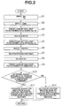
- Figure 2 is a flow chart implementing the present invention.
- Figure 3 is an overall A/F map showing variation characteristic of overall air/fuel ratio (AFall) within cylinder against varying operating conditions as represented by engine speed (Ne) and load request (Te).
- AFall overall air/fuel ratio
- Figure 4 is a local A/F map showing variation characteristic of local air/fuel ratio (AF2) against varying operating conditions as represented by engine speed (Ne) and load request (Te).
- AF2 local air/fuel ratio
- Figure 5 is an injection map showing variation characteristic of injection time of fuel for ignition (IT2) against varying operating conditions as represented by engine speed (Ne) and load request (Te).
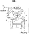
- Figure 6 is a block diagram illustrating a second embodiment of an internal combustion engine according to the present invention.
- Figure 7 is a block diagram illustrating a third embodiment of an internal combustion engine according to the present invention.
- Figure 8 is a block diagram illustrating a fourth embodiment of an internal combustion engine according to the present invention.
- Figure 1 provides a block diagram of an internal combustion engine operated on gasoline fuel.
- FIG. 1 the area of a combustion chamber of the engine is shown.
- the engine has a cylinder head 10 and a cylinder block 11. It has at least one cylinder 12 with a piston 13 reciprocating therein to define a combustion chamber 3.
- a spark plug 1 and a fuel injection valve 2 are provided for combustion chamber 3. Spark plug 1 can produce spark within combustion chamber 3, while fuel injection valve 2 can inject fuel directly into combustion chamber 3.
- Combustion chamber 3 is communicating with intake and exhaust ports 4 and 6 via intake and exhaust valves 14 and 15, which are actuated by variable valve controllers 40 and 42.
- Various sensors are provided to assist in accomplishing auto-ignition at appropriate ignition point over wide range of engine speed and load.
- Various sensors may include an air flow meter 5 located upstream of intake port 4 for measuring intake air quantity, a crank angle sensor 7, and an accelerator angle sensor 8.
- Crank angle sensor 7 detects crank angle or crank position of the engine.
- Accelerator angle sensor 8 detects accelerator opening degree representing load request by an operator.
- Engine controller 9 receives signals from the various sensors and determines injection time and fuel quantity for gasoline fuel injections as well as spark time.
- combustion chamber 3 is defined by a first combustion space portion 3a between cylinder head 10 and a crown surface of piston 13, and a second combustion space portion 3b recessed inwardly from the crown surface of piston 13.
- step S1 controller 9 inputs information as to engine speed Ne and load request Te by carrying out calculation based on output signal from crank angle sensor 7 and calculation based on output signal from accelerator angle sensor 8.
- step S2 controller 9 inputs information as to intake air quantity Qair by carrying out calculation based on output signal from air flow meter 5.
- controller 9 performs a table look-up operation of Figure 3 map to determine a value of overall air/fuel ratio AFall using engine speed Ne and load request Te. Appropriate values of overall air/fuel ratio AFall may be found in the map of Figure 3.
- the overall air/fuel ratio AFall represents an air/fuel ratio required if the cylinder is filled with homogeneous charge.
- step S5 controller 9 performs a table look-up operation of Figure 4 map to determine local air/fuel ratio AF2 using engine speed Ne and load request Te.
- Local air/fuel ratio AF2 represents air/fuel ratio of a local mixture formed around spark plug 1. Appropriate values of local air/fuel ratio AF2 may be found in the map of Figure 4. As shown in Figure 4, during operation with high load where the local air/fuel mixture is to be ignited by external assist such as a spark in this embodiment, local air/fuel ratio AF2 is held at the stoichiometry.
- local air/fuel ratio AF2 is greater than the stoichiometry to provide lean local air/fuel mixture. The lighter the load request becomes, the leaner the local air/fuel mixture becomes.
- controller 9 inputs a volume ratio (V3b/V3a) between second combustion space 3b and first combustion space 3a at top dead center of piston 13. This ratio is determined by design values of the engine and stored in a memory of controller 9.
- controller 9 performs table look-up operation of Figure 5 map using engine speed Ne and load request Te to determine injection time IT2 for injection of fuel for ignition. Appropriate values of injection time IT2 may be found in the map of Figure 5.
- injection time IT2 is held constant.
- injection time IT2 advances as load request increases.
- the setting is such that injection time IT2 during operation with high load is retarded than injection time IT2 during operation with light or middle load. This setting is needed to prevent auto-ignition within the local air/fuel mixture prior to spark, which is set at a crank position around top dead center.
- step S10 controller 9 determines based on engine speed Ne and load request Te whether or not external assist in the form of spark is required to produce flame to trigger auto-ignition within the main air/fuel mixture. If this is the case, control goes to step S11. In step S11, controller 9 instructs ignition system to produce spark at spark timing to ignite the local air/fuel mixture to produce flame to trigger auto-ignition within the main air/fuel mixture. If the interrogation in step S10 results in negative so that external assist in the form of spark is not required, control goes to step S12. In step S12, controller 9 will not take any action for production of spark, letting local air/fuel mixture burn by auto-ignition to trigger auto-ignition of the main air/fuel mixture.
- fuel injection valve 2 During induction stroke of piston, fuel injection valve 2 carries out a first injection of quantity Q1 of fuel.
- the fuel injected mixes with intake air to form main homogeneous air/fuel mixture within cylinder 12.
- Air/fuel ratio of the main air/fuel mixture is set on the lean side of the stoichiometry so that auto-ignition within the main air/fuel mixture will not take place at around top dead center of compression stroke.
- fuel injection valve 2 carries out a second injection of quantity Q2 of fuel for ignition at injection time IT2.
- fuel quantity Q2 for second injection is set to provide local air/fuel mixture having AF2 as great as the stoichiometry. If it is determined that the external assist is not needed, fuel quantity Q2 is set to provide very lean local air/fuel mixture with AF2 almost twice as great as the stoichiometry. In this manner, during operation with light load, auto-ignition takes place throughout the local air/fuel mixture to trigger auto-ignition within the main air/fuel mixture. During operation with high load, flame propagation due to spark ignition of the local air/fuel mixture will trigger auto-ignition within the main air/fuel mixture.
- Figure 6 provides a diagram illustrating the second embodiment according to the present invention.
- the second embodiment is substantially the same as the first embodiment. However, the second embodiment is different from the first embodiment in that a piston 13 is not provided with a recess within its crown, and a cylinder head 10 has a pent roof type combustion chamber. As different from the first embodiment, a fuel injection valve 2 is arranged below intake port 4 for direct injection of fuel for dispersion around spark plug 1.
- a combustion chamber 3 is divided into a first combustion space 3a and a second combustion space 3b.
- the second combustion space 3b has a volume around spark plug 1.
- the second combustion space has a volume resulting from subtracting the volume of second combustion space 3b from the volume of combustion chamber 3 at top dead center.
- a volume ratio V3b/V3a is calculated based on the first and second combustion spaces 3a and 3b defined as above. Using the volume ratio thus determined, the same logic as explained along the flow chart of Figure 2 is equally applicable to this second embodiment.
- the present invention is applicable to various different types of conventional internal combustion engines with minor modification.
- the various engines include a direct cylinder injection diesel engine and a direct cylinder injection stratified gasoline engine, both of which is quipped with a piston with a crown recess as shown in Figure 1, and a popular gasoline engine as shown in Figure 6. Accordingly, no substantially modification to existing engines is required to apply the present invention.
- Figure 7 provides a diagram illustrating the third embodiment of the invention.
- external assist in the form of additional compression is used instead of spark.
- the third embodiment is substantially the same as the second embodiment except the provision of a control piston 21 instead of the spark plug 1 and the use of a single injection during operation with high load.
- control piston 21 is reciprocally located within a cylindrical bore 23. Cylindrical bore 23 is in direct communication with a combustion chamber 3.
- a cam driver 22 is rendered operable to drive control piston 21. When rendered inoperable, cam driver 22 cannot drive control piston 21.
- cam driver 22 is rendered operable to drive control piston 21 at around top dead center of compression stroke, adding additional compression to the content of cylinder 12 to cause auto-ignition of main air/fuel mixture.
- cam driver 22 is rendered inoperable to drive control piston 21, leaving control piston 21 at rest.
- control piston 21 Additional power is required for activation of control piston 21.
- the control piston 21 is left at rest during operation with light load so that increase in fuel consumption due to activation of control piston 21 is suppressed.
- Figure 8 provides a diagram illustrating the fourth embodiment of the invention.
- external assist in the form of injection of ignitable fuel is used instead of additional compression or spark.
- This embodiment is substantially the same as the third embodiment except the provision of a fuel injection valve 31 instead of the control piston 21.
- fuel injection valve 31 is provided in addition to a fuel injection valve 2.
- Fuel injection valve 2 carries out injection of fuel with low cetane number during induction stroke, thereby to form lean air/fuel mixture within a combustion chamber 3 around top dead center of compression stroke.
- Fuel injection valve 31 is provided for carrying out injection of ignitable fuel with high cetane number at injection time around top dead center.
- the ignitable fuel such as, gas oil, is delivered to fuel injection valve 31 from a separate tank.
- fuel injection valve 2 During operation with high load, the fuel injection through fuel injection valve 2 causes creation of lean main air/fuel mixture within cylinder 12. Subsequently, at injection time during compression stroke, the ignitable fuel is injected through fuel injection valve 31. Auto-ignition takes place within the ignitable fuel immediately after its injection, causing auto-ignition within the main air/fuel mixture. During operation with light load, injection of the ignitable fuel will not be carried out. Under this operating conditions, similarly to the other embodiments, fuel injection valve 2 carries out first injection of fuel during induction stroke to form lean main air/fuel mixture, and second injection of fuel for ignition at injection time during the subsequent compression stroke.
- the use of ignitable fuel is limited to operation with light load so that volume of the tank for the ignitable fuel may be reduced to the required minimum level.
Landscapes
- Engineering & Computer Science (AREA)
- Chemical & Material Sciences (AREA)
- Combustion & Propulsion (AREA)
- Mechanical Engineering (AREA)
- General Engineering & Computer Science (AREA)
- Oil, Petroleum & Natural Gas (AREA)
- Electrical Control Of Air Or Fuel Supplied To Internal-Combustion Engine (AREA)
- Combined Controls Of Internal Combustion Engines (AREA)
- Combustion Methods Of Internal-Combustion Engines (AREA)
Abstract
Description
- The present invention relates to an internal combustion engine operated on auto-ignition combustion.
- JP-A 10-196424 discloses an auto-ignition internal combustion engine. According to this known engine, each cylinder has a control piston in addition to a reciprocating piston. Time of auto-ignition of air/fuel mixture is governed by the control piston, which provides additional compression around top dead center of reciprocating piston. With this additional compression, the air/fuel mixture can be elevated in temperature high enough for auto-ignition.
- JP-A 11-210539 discloses a spark assist type auto-ignition internal combustion engine. According to this known engine, an open time of intake valve is adjusted to vary amount of burnt gas to be drawn during induction stroke of piston, thereby to vary temperature of gas within a combustion chamber. A temperature sensor is provided to detect the temperature of gas. If it is determined that the temperature of gas within the combustion chamber fail to match a target temperature level, the open time of the intake valve is adjusted to maintain the gas temperature as high as the target temperature level. At the target temperature level, the air/fuel mixture starts auto-ignition if spark is produced by a spark plug.
- Auto-ignition can occur when certain conditions are met within a charge of air/fuel mixture. With auto-ignition, bulk combustion takes place initiated simultaneously from many ignition sites within the charge, resulting in combustion with low local burning temperature. As different from spark-ignition combustion based on propagating flame front, in auto-ignition combustion where the combustion is uniformly distributed throughout the charge from many ignition sites, the burnt gas temperature is substantially homogeneous with much lower local temperature values, resulting in very low NOx emission. This type of combustion is disadvantageous if relatively rich air/fuel mixture is used against increased load request. If a charge of rich air/fuel mixture is combusted from many ignition sites, cylinder pressure rises too rapidly, resulting in production of noticeable vibration and noise.
- One proposal to avoid such rapid increase in cylinder pressure is to set ignition time at around or after top dead center of compression stroke. This causes combustion of most of fuel within the charge to take place after top dead center of compression stroke. With delayed ignition, initial stage combustion progresses as a piston descends, resulting in increased tendency to provide unstable combustion. Thus, there is a limit to retarding the ignition time.
- Accordingly, for extending range of auto-ignition combustion toward increased load, there remains a need for technique to ensure stable ignition of charge even with delayed time of ignition.
- If the known technique of JP-A 10-196424 is employed for carrying out auto-ignition during operation with high load, time of ignition may be adjusted to a desired relatively delayed crank position. This technique is satisfactory in adjusting ignition time, but needs additional power to activate the control piston, deteriorating fuel economy. Particularly, the degree of deterioration in fuel economy becomes great during light load operation where influence of cooling loss upon fuel economy is great.
- If the known technique of JP-A 11-210539 is employed for carrying out stable ignition of homogenous charge, time of ignition can be held invariable due to assist by spark from a spark plug. The use of spark has proven to be effective under conditions where auto-ignition before top dead center of compression stroke is required. However, experiments conducted by the inventors of this application have revealed that it is impossible to retard ignition time enough to cause auto-ignition combustion to take place around or after the top dead center. Therefore, it is confirmed that this known technique is not effective in carrying out stable auto-ignition combustion during operation with high load.
- A stratified charge between local relatively rich air/fuel mixture and the surrounding relatively lean air/fuel mixture may accomplish stable ignition in auto-ignition combustion. In the stratified charge, burning due to auto-ignition is initiated from the local rich air/fuel mixture, and the temperature and pressure due to this burning causes auto-ignition combustion within the surrounding lean air/fuel mixture. Time of fuel injection can determine time of ignition. If, however, fuel with low cetane number such as gasoline, is used, it is difficult to hold time of ignition invariable if time of fuel injection is fixed. Retarding time of ignition to a crank position around or after top dead center of compression stroke is too difficult to accomplish. Therefore, this known technique is not effective in carrying out stable auto-ignition combustion during operation with high load.
- Use of ignitable fuel is proposed to hold time of ignition invariable. This proposal makes it possible to retard combustion event to a crank position after top dead center of compression stroke, thus allowing auto-ignition combustion during operation with high load. If this technique is applied to a gasoline internal combustion engine, a tank for ignitable fuel requires additional space. To minimize the additional space, volume of a tank should be reduced by carrying out injection of ignitable fuel only when required to suppress consumption of ignitable fuel.
- A so-called spark assist type stratified charge auto-ignition combustion is known. According to this combustion process, local air/fuel mixture around a spark plug is made rich enough to be ignitable by a spark. Burning of the local air/fuel mixture causes auto-ignition of the surrounding relatively lean air/fuel mixture. This combustion process is considered to be effective during operation with high load because time of ignition may be retarded to a crank position around or after top dead center of compression stroke. The air/fuel mixture around the spark plug should be set around the stoichiometry for stable flame propagation. If it is lean, it becomes difficult to ignite by spark. If it is too rich, it turns into soot and hydrocarbon (HC) after burning initiated by spark. This spark assist type combustion process cannot provide stable combustion throughout the charge within cylinder during operation with light load. Fuel quantity for injection decreases during operation with light load. If the local air/fuel mixture around spark plug is set around the stoichiometry, the air/fuel mixture occupying the remaining portion of cylinder inevitably becomes extremely lean, resulting in unstable auto-ignition throughout the cylinder charge although stable flame propagation throughout the local air/fuel mixture is provided. As a result, stable combustion is not expected during operation with light load. Flame propagation produces NOx, and unstable combustion produces hydrocarbon (HC), resulting in increased emission of NOx and HC.
- An object of the present invention is to accomplish auto-ignition combustion of an internal combustion engine over extended range of operating conditions.
- In one aspect of the present invention, the above object is achieved by an internal combustion engine. The engine has at least one cylinder, a reciprocating piston within the cylinder to define a combustion chamber. In the engine, auto-ignition within main air/fuel mixture is triggered by auto-ignition of local air/fuel mixture under first predetermined operating conditions, and auto-ignition within the main air/fuel mixture is triggered by external assist under second predetermined operating conditions.
- The present invention will be more fully appreciated as the same becomes better understood from the following detailed description when considered in connection with the accompanying drawings, in which like reference numerals and characters designate like or corresponding parts through the several views.
- Figure 1 is a block diagram illustrating a first embodiment of an internal combustion engine according to the present invention.
- Figure 2 is a flow chart implementing the present invention.
- Figure 3 is an overall A/F map showing variation characteristic of overall air/fuel ratio (AFall) within cylinder against varying operating conditions as represented by engine speed (Ne) and load request (Te).
- Figure 4 is a local A/F map showing variation characteristic of local air/fuel ratio (AF2) against varying operating conditions as represented by engine speed (Ne) and load request (Te).
- Figure 5 is an injection map showing variation characteristic of injection time of fuel for ignition (IT2) against varying operating conditions as represented by engine speed (Ne) and load request (Te).
- Figure 6 is a block diagram illustrating a second embodiment of an internal combustion engine according to the present invention.
- Figure 7 is a block diagram illustrating a third embodiment of an internal combustion engine according to the present invention.
- Figure 8 is a block diagram illustrating a fourth embodiment of an internal combustion engine according to the present invention.
- Figure 1 provides a block diagram of an internal combustion engine operated on gasoline fuel.
- In Figure 1, the area of a combustion chamber of the engine is shown. The engine has a
cylinder head 10 and acylinder block 11. It has at least onecylinder 12 with apiston 13 reciprocating therein to define acombustion chamber 3. Aspark plug 1 and afuel injection valve 2 are provided forcombustion chamber 3.Spark plug 1 can produce spark withincombustion chamber 3, whilefuel injection valve 2 can inject fuel directly intocombustion chamber 3.Combustion chamber 3 is communicating with intake andexhaust ports exhaust valves variable valve controllers - Various sensors are provided to assist in accomplishing auto-ignition at appropriate ignition point over wide range of engine speed and load. Various sensors may include an
air flow meter 5 located upstream ofintake port 4 for measuring intake air quantity, acrank angle sensor 7, and anaccelerator angle sensor 8. Crankangle sensor 7 detects crank angle or crank position of the engine.Accelerator angle sensor 8 detects accelerator opening degree representing load request by an operator. -
Engine controller 9 receives signals from the various sensors and determines injection time and fuel quantity for gasoline fuel injections as well as spark time. - According to the first embodiment,
combustion chamber 3 is defined by a firstcombustion space portion 3a betweencylinder head 10 and a crown surface ofpiston 13, and a secondcombustion space portion 3b recessed inwardly from the crown surface ofpiston 13. - Referring to Figure 2, the flow chart illustrates a control routine of the first embodiment according to the present invention. In step S1,
controller 9 inputs information as to engine speed Ne and load request Te by carrying out calculation based on output signal fromcrank angle sensor 7 and calculation based on output signal fromaccelerator angle sensor 8. In step S2,controller 9 inputs information as to intake air quantity Qair by carrying out calculation based on output signal fromair flow meter 5. - In the next step S3,
controller 9 performs a table look-up operation of Figure 3 map to determine a value of overall air/fuel ratio AFall using engine speed Ne and load request Te. Appropriate values of overall air/fuel ratio AFall may be found in the map of Figure 3. The overall air/fuel ratio AFall represents an air/fuel ratio required if the cylinder is filled with homogeneous charge. - In step S4,
controller 9 determines total fuel quantity Qall for injections per one cycle by calculating the following equation: - In step S5,
controller 9 performs a table look-up operation of Figure 4 map to determine local air/fuel ratio AF2 using engine speed Ne and load request Te. Local air/fuel ratio AF2 represents air/fuel ratio of a local mixture formed aroundspark plug 1. Appropriate values of local air/fuel ratio AF2 may be found in the map of Figure 4. As shown in Figure 4, during operation with high load where the local air/fuel mixture is to be ignited by external assist such as a spark in this embodiment, local air/fuel ratio AF2 is held at the stoichiometry. During operation with light or middle load where the external assist such as spark is not required and auto-ignition takes place throughout the local air/fuel mixture, local air/fuel ratio AF2 is greater than the stoichiometry to provide lean local air/fuel mixture. The lighter the load request becomes, the leaner the local air/fuel mixture becomes. - In step S6,
controller 9 inputs a volume ratio (V3b/V3a) betweensecond combustion space 3b andfirst combustion space 3a at top dead center ofpiston 13. This ratio is determined by design values of the engine and stored in a memory ofcontroller 9. - In step S7,
controller 9 determines fuel quantity Q2 for injection of fuel for ignition based on the volume ratio (V3b/V3a), intake air quantity Qair, total fuel quantity Qall, and local air/fuel ratio AF2 by calculating the following equation: - In step S8,
controller 9 determines fuel quantity Q1 for injection to form main air/fuel mixture by calculating the following equation: - In step S9,
controller 9 performs table look-up operation of Figure 5 map using engine speed Ne and load request Te to determine injection time IT2 for injection of fuel for ignition. Appropriate values of injection time IT2 may be found in the map of Figure 5. As shown in Figure 5, during operation with high load where the local mixture is to be ignited by external assist in the form of spark, injection time IT2 is held constant. During operation with light or middle load where external assist is not required to cause auto-ignition to take place throughout the local mixture, injection time IT2 advances as load request increases. The setting is such that injection time IT2 during operation with high load is retarded than injection time IT2 during operation with light or middle load. This setting is needed to prevent auto-ignition within the local air/fuel mixture prior to spark, which is set at a crank position around top dead center. - In step S10,
controller 9 determines based on engine speed Ne and load request Te whether or not external assist in the form of spark is required to produce flame to trigger auto-ignition within the main air/fuel mixture. If this is the case, control goes to step S11. In step S11,controller 9 instructs ignition system to produce spark at spark timing to ignite the local air/fuel mixture to produce flame to trigger auto-ignition within the main air/fuel mixture. If the interrogation in step S10 results in negative so that external assist in the form of spark is not required, control goes to step S12. In step S12,controller 9 will not take any action for production of spark, letting local air/fuel mixture burn by auto-ignition to trigger auto-ignition of the main air/fuel mixture. - During induction stroke of piston,
fuel injection valve 2 carries out a first injection of quantity Q1 of fuel. The fuel injected mixes with intake air to form main homogeneous air/fuel mixture withincylinder 12. Air/fuel ratio of the main air/fuel mixture is set on the lean side of the stoichiometry so that auto-ignition within the main air/fuel mixture will not take place at around top dead center of compression stroke. Subsequently, during the second half of compression stroke,fuel injection valve 2 carries out a second injection of quantity Q2 of fuel for ignition at injection time IT2. If it is determined based on engine speed Ne and load request Te that external assist in the form of spark is needed, fuel quantity Q2 for second injection is set to provide local air/fuel mixture having AF2 as great as the stoichiometry. If it is determined that the external assist is not needed, fuel quantity Q2 is set to provide very lean local air/fuel mixture with AF2 almost twice as great as the stoichiometry. In this manner, during operation with light load, auto-ignition takes place throughout the local air/fuel mixture to trigger auto-ignition within the main air/fuel mixture. During operation with high load, flame propagation due to spark ignition of the local air/fuel mixture will trigger auto-ignition within the main air/fuel mixture. - As engine speed Ne increases, time, which may be used for reform of fuel toward auto-ignition, becomes short, hampering stable auto-ignition of local air/fuel mixture. Therefore, according to this embodiment, the higher the engine speed Ne becomes, the further operation points at which external assist is required extend in such a direction as to cause a reduction in load request Te, as readily seen from Figures 4 and 5.
- Besides, during operation at low engine speeds, like idle operation, there is sufficient time which may be used for reform of fuel, but cooling loss is great to cause release of heat from cylinder, making it difficult to hold temperature within the cylinder high enough for auto-ignition. Therefore, according to this embodiment, external assist in the form of spark is provided to ensure ignition of the local air/fuel mixture to trigger the main air/fuel mixture during operation at engine speeds falling in a predetermined low engine speed range irrespective of magnitude of load request, as shown in Figures 4 and 5.
- Figure 6 provides a diagram illustrating the second embodiment according to the present invention.
- The second embodiment is substantially the same as the first embodiment. However, the second embodiment is different from the first embodiment in that a
piston 13 is not provided with a recess within its crown, and acylinder head 10 has a pent roof type combustion chamber. As different from the first embodiment, afuel injection valve 2 is arranged belowintake port 4 for direct injection of fuel for dispersion aroundspark plug 1. - In applying the control logic illustrated by the flow chart of Figure 2, a
combustion chamber 3 is divided into afirst combustion space 3a and asecond combustion space 3b. Thesecond combustion space 3b has a volume aroundspark plug 1. The second combustion space has a volume resulting from subtracting the volume ofsecond combustion space 3b from the volume ofcombustion chamber 3 at top dead center. A volume ratio V3b/V3a is calculated based on the first andsecond combustion spaces - From the preceding description it will be appreciated that the present invention is applicable to various different types of conventional internal combustion engines with minor modification. The various engines include a direct cylinder injection diesel engine and a direct cylinder injection stratified gasoline engine, both of which is quipped with a piston with a crown recess as shown in Figure 1, and a popular gasoline engine as shown in Figure 6. Accordingly, no substantially modification to existing engines is required to apply the present invention.
- Figure 7 provides a diagram illustrating the third embodiment of the invention. In the third embodiment, external assist in the form of additional compression is used instead of spark.
- The third embodiment is substantially the same as the second embodiment except the provision of a
control piston 21 instead of thespark plug 1 and the use of a single injection during operation with high load. - In Figure 7,
control piston 21 is reciprocally located within acylindrical bore 23. Cylindrical bore 23 is in direct communication with acombustion chamber 3. Acam driver 22 is rendered operable to drivecontrol piston 21. When rendered inoperable,cam driver 22 cannot drivecontrol piston 21. - According to this embodiment, during operation with high load,
cam driver 22 is rendered operable to drivecontrol piston 21 at around top dead center of compression stroke, adding additional compression to the content ofcylinder 12 to cause auto-ignition of main air/fuel mixture. During operation with light load,cam driver 22 is rendered inoperable to drivecontrol piston 21, leavingcontrol piston 21 at rest. - Additional power is required for activation of
control piston 21. However, thecontrol piston 21 is left at rest during operation with light load so that increase in fuel consumption due to activation ofcontrol piston 21 is suppressed. - Figure 8 provides a diagram illustrating the fourth embodiment of the invention. In this embodiment, external assist in the form of injection of ignitable fuel is used instead of additional compression or spark.
- This embodiment is substantially the same as the third embodiment except the provision of a
fuel injection valve 31 instead of thecontrol piston 21. - In the fourth embodiment,
fuel injection valve 31 is provided in addition to afuel injection valve 2.Fuel injection valve 2 carries out injection of fuel with low cetane number during induction stroke, thereby to form lean air/fuel mixture within acombustion chamber 3 around top dead center of compression stroke.Fuel injection valve 31 is provided for carrying out injection of ignitable fuel with high cetane number at injection time around top dead center. The ignitable fuel, such as, gas oil, is delivered tofuel injection valve 31 from a separate tank. - During operation with high load, the fuel injection through
fuel injection valve 2 causes creation of lean main air/fuel mixture withincylinder 12. Subsequently, at injection time during compression stroke, the ignitable fuel is injected throughfuel injection valve 31. Auto-ignition takes place within the ignitable fuel immediately after its injection, causing auto-ignition within the main air/fuel mixture. During operation with light load, injection of the ignitable fuel will not be carried out. Under this operating conditions, similarly to the other embodiments,fuel injection valve 2 carries out first injection of fuel during induction stroke to form lean main air/fuel mixture, and second injection of fuel for ignition at injection time during the subsequent compression stroke. - According to the fourth embodiment, the use of ignitable fuel is limited to operation with light load so that volume of the tank for the ignitable fuel may be reduced to the required minimum level.
- While the present invention has been particularly described, in conjunction with preferred implementations and embodiments, it is evident that many alternatives, modifications and variations will be apparent to those skilled in the art in light of the foregoing description. It is therefore contemplated that the appended claims will embrace any such alternatives, modifications and variations as falling within the true scope and spirit of the present invention.
- This application claims the priority of Japanese Patent Applications No. 2000-176297, filed June 13, 2000, the disclosure of which is hereby incorporated by reference in its entirety.
Claims (9)
- An internal combustion engine having at least one cylinder (12), a reciprocating piston (13) within the cylinder to define a combustion chamber (3) therein, characterized in that auto-ignition within main air/fuel mixture is triggered by auto-ignition of local air/fuel mixture under first predetermined operating conditions, and in that auto-ignition within the main air/fuel mixture is triggered by external assist under second predetermined operating conditions.
- The internal combustion engine as claimed in claim 1, characterized in that the local air/fuel mixture occupies a combustion space (3a) of the combustion chamber (3) and starts to burn by auto-ignition under conditions created within the cylinder (12) under the first predetermined operating conditions.
- The internal combustion engine as claimed in claim 1 or 2, characterized in that the external assist includes a second local air/fuel mixture and spark produced by a spark plug (1) to cause the second local air/fuel mixture to burn, or additional compression provided by a control piston (21) to initiate auto-ignition within the main air/fuel mixture, or injection of ignitable fuel from a fuel injection valve (31) to burn to initiate auto-ignition within the main air/fuel mixture.
- The internal combustion engine as claimed in claim 1 or 2, characterized in that a fuel injection valve (2) carries out injection of fuel for auto-ignition under the first predetermined operating conditions and for ignition by the external assist under the second predetermined operating conditions.
- The internal combustion engine as claimed in claim 4, characterized in that the operating conditions are represented by engine speed (Ne) and load request (Te), and in that the higher engine speed (Ne) becomes, the further operation points at which the external assist is required extend in such a direction as to cause a reduction in load request (Te).
- The internal combustion engine as claimed in claim 4 or 5, characterized in that the second predetermined operating conditions include engine operation with high load, engine operation at idling or low engine speeds.
- The internal combustion engine as claimed in any one of the preceding claims 4 to 6, characterized in that the injection of fuel for ignition takes place at an injection time during compression stroke of the piston (13).
- The internal combustion engine as claimed in any one of the preceding claims 4 to 7, characterized in that the fuel injected for ignition begins to burn at around top dead center of compression stroke of the piston (13).
- The internal combustion engine as claimed in any one of claims 4 to 8, characterized in that fuel quantity for injection of fuel for ignition is greater under the second predetermined operating conditions than the fuel quantity under the first predetermined operating conditions.
Applications Claiming Priority (2)
| Application Number | Priority Date | Filing Date | Title |
|---|---|---|---|
| JP2000176297 | 2000-06-13 | ||
| JP2000176297A JP3835130B2 (en) | 2000-06-13 | 2000-06-13 | Compression self-ignition internal combustion engine |
Publications (3)
| Publication Number | Publication Date |
|---|---|
| EP1164276A2 true EP1164276A2 (en) | 2001-12-19 |
| EP1164276A3 EP1164276A3 (en) | 2003-09-10 |
| EP1164276B1 EP1164276B1 (en) | 2008-03-05 |
Family
ID=18678034
Family Applications (1)
| Application Number | Title | Priority Date | Filing Date |
|---|---|---|---|
| EP01114226A Expired - Lifetime EP1164276B1 (en) | 2000-06-13 | 2001-06-12 | Internal combustion engine with external assist for stable auto-ignition |
Country Status (3)
| Country | Link |
|---|---|
| EP (1) | EP1164276B1 (en) |
| JP (1) | JP3835130B2 (en) |
| DE (1) | DE60133064T2 (en) |
Cited By (4)
| Publication number | Priority date | Publication date | Assignee | Title |
|---|---|---|---|---|
| EP1953375A1 (en) * | 2007-01-30 | 2008-08-06 | Mazda Motor Corporation | Method and computer program product of operating an internal combustion engine as well as engine operating system |
| US7690368B2 (en) | 2006-06-16 | 2010-04-06 | Ford Global Technologies, Llc | System and method for facilitating homogeneous charge compression ignition |
| US7703438B2 (en) | 2006-06-16 | 2010-04-27 | Ford Global Technologies, Llc | System and method for facilitating homogeneous charge compression ignition |
| CN112166351A (en) * | 2018-05-02 | 2021-01-01 | 探索技术股份公司 | Pneumatic actuator, pressure wave generator and method for operating a pressure wave generator |
Families Citing this family (6)
| Publication number | Priority date | Publication date | Assignee | Title |
|---|---|---|---|---|
| JP4023239B2 (en) * | 2002-07-10 | 2007-12-19 | トヨタ自動車株式会社 | INTERNAL COMBUSTION ENGINE FOR COMPRESSED IGNITION OF MIXED AIR AND CONTROL METHOD FOR INTERNAL COMBUSTION ENGINE |
| JP2008163815A (en) * | 2006-12-27 | 2008-07-17 | Honda Motor Co Ltd | Fuel injection control device for internal combustion engine |
| JP5035088B2 (en) * | 2007-08-06 | 2012-09-26 | 日産自動車株式会社 | engine |
| WO2009102744A1 (en) * | 2008-02-15 | 2009-08-20 | Gm Global Technology Operations, Inc. | Method for controlling a spark-ignition direct-injection internal combustion engine at low loads |
| JP5439110B2 (en) | 2009-10-06 | 2014-03-12 | コスモ石油株式会社 | Combustion timing prediction method for compression self-ignition internal combustion engine, control method for compression self-ignition internal combustion engine, and compression self-ignition internal combustion engine system |
| JP5543843B2 (en) * | 2010-05-20 | 2014-07-09 | 本田技研工業株式会社 | Control device for internal combustion engine |
Citations (2)
| Publication number | Priority date | Publication date | Assignee | Title |
|---|---|---|---|---|
| JPH10196424A (en) | 1996-12-28 | 1998-07-28 | Toyota Central Res & Dev Lab Inc | Compression ignition combustion method of air-fuel mixture and compression ignition piston internal combustion engine of air-fuel mixture |
| JPH11210539A (en) | 1998-01-30 | 1999-08-03 | Toyota Motor Corp | Spark-assisted self-ignition internal combustion engine |
Family Cites Families (7)
| Publication number | Priority date | Publication date | Assignee | Title |
|---|---|---|---|---|
| JPS6293164U (en) * | 1985-11-30 | 1987-06-13 | ||
| JP3189734B2 (en) * | 1996-12-19 | 2001-07-16 | 三菱自動車工業株式会社 | Spark ignition direct injection internal combustion engine |
| JPH10238374A (en) * | 1997-02-21 | 1998-09-08 | Daihatsu Motor Co Ltd | Premixture ignition internal combustion engine and ignition timing control method |
| US6227151B1 (en) * | 1997-08-01 | 2001-05-08 | Ford Global Technologies, Inc. | Gasoline internal combustion engine |
| JPH11101127A (en) * | 1997-09-26 | 1999-04-13 | Mitsubishi Motors Corp | Combustion control device |
| WO1999042718A1 (en) * | 1998-02-23 | 1999-08-26 | Cummins Engine Company, Inc. | Premixed charge compression ignition engine with optimal combustion control |
| JP3911912B2 (en) * | 1999-06-23 | 2007-05-09 | 株式会社日立製作所 | Engine control system and control method |
-
2000
- 2000-06-13 JP JP2000176297A patent/JP3835130B2/en not_active Expired - Fee Related
-
2001
- 2001-06-12 DE DE60133064T patent/DE60133064T2/en not_active Expired - Lifetime
- 2001-06-12 EP EP01114226A patent/EP1164276B1/en not_active Expired - Lifetime
Patent Citations (2)
| Publication number | Priority date | Publication date | Assignee | Title |
|---|---|---|---|---|
| JPH10196424A (en) | 1996-12-28 | 1998-07-28 | Toyota Central Res & Dev Lab Inc | Compression ignition combustion method of air-fuel mixture and compression ignition piston internal combustion engine of air-fuel mixture |
| JPH11210539A (en) | 1998-01-30 | 1999-08-03 | Toyota Motor Corp | Spark-assisted self-ignition internal combustion engine |
Cited By (6)
| Publication number | Priority date | Publication date | Assignee | Title |
|---|---|---|---|---|
| US7690368B2 (en) | 2006-06-16 | 2010-04-06 | Ford Global Technologies, Llc | System and method for facilitating homogeneous charge compression ignition |
| US7703438B2 (en) | 2006-06-16 | 2010-04-27 | Ford Global Technologies, Llc | System and method for facilitating homogeneous charge compression ignition |
| US8025046B2 (en) | 2006-06-16 | 2011-09-27 | Ford Global Technologies, Llc | System and method for facilitating homogeneous charge compression ignition |
| EP1953375A1 (en) * | 2007-01-30 | 2008-08-06 | Mazda Motor Corporation | Method and computer program product of operating an internal combustion engine as well as engine operating system |
| US7669578B2 (en) | 2007-01-30 | 2010-03-02 | Mazda Motor Corporation | Method of operating an internal combustion engine |
| CN112166351A (en) * | 2018-05-02 | 2021-01-01 | 探索技术股份公司 | Pneumatic actuator, pressure wave generator and method for operating a pressure wave generator |
Also Published As
| Publication number | Publication date |
|---|---|
| EP1164276A3 (en) | 2003-09-10 |
| EP1164276B1 (en) | 2008-03-05 |
| DE60133064T2 (en) | 2008-06-12 |
| JP3835130B2 (en) | 2006-10-18 |
| DE60133064D1 (en) | 2008-04-17 |
| JP2001355449A (en) | 2001-12-26 |
Similar Documents
| Publication | Publication Date | Title |
|---|---|---|
| US6619255B2 (en) | Combustion event indicative parameter dependent control for auto-ignited combustion | |
| US6725827B2 (en) | Spark ingition stratified combustion internal combustion engine | |
| JP3500951B2 (en) | Non-throttle compression-ignition internal combustion engine and control method thereof | |
| US6636797B2 (en) | Enhanced multiple injection for auto-ignition in internal combustion engines | |
| JP4836088B2 (en) | Control device and control method for compression self-ignition internal combustion engine | |
| US6267097B1 (en) | Compression self-igniting gasoline engine | |
| US6345499B1 (en) | Catalyst light-off method and device for direct injection engine | |
| US7051701B2 (en) | Direct fuel injection/spark ignition engine control device | |
| EP0491381B1 (en) | A fuel injection control device for an internal combustion engine | |
| CN101405497B (en) | Fuel injection control device and fuel injection control method for internal combustion engine | |
| US7096853B2 (en) | Direct fuel injection/spark ignition engine control device | |
| JP2021113549A (en) | Engine system | |
| JP2023020227A (en) | engine system | |
| JP2006183653A (en) | Gas fuel engine | |
| EP1164276B1 (en) | Internal combustion engine with external assist for stable auto-ignition | |
| CN101213368A (en) | Method and system for controlling engine noise | |
| JP3257430B2 (en) | Exhaust heating device | |
| JP2003049650A (en) | Compression self-ignition internal combustion engine | |
| JP2751626B2 (en) | In-cylinder direct injection spark ignition engine | |
| JP2023020226A (en) | engine system | |
| JP2006052687A (en) | In-cylinder direct injection internal combustion engine | |
| JPH11107792A (en) | Premix compression ignition type engine | |
| JP3084040B2 (en) | Control device for two-stroke engine | |
| JPH04353243A (en) | Combustion control device | |
| JPH07189767A (en) | Control apparatus and method for spark ignition internal combustion engine |
Legal Events
| Date | Code | Title | Description |
|---|---|---|---|
| PUAI | Public reference made under article 153(3) epc to a published international application that has entered the european phase |
Free format text: ORIGINAL CODE: 0009012 |
|
| 17P | Request for examination filed |
Effective date: 20010612 |
|
| AK | Designated contracting states |
Kind code of ref document: A2 Designated state(s): AT BE CH CY DE DK ES FI FR GB GR IE IT LI LU MC NL PT SE TR |
|
| AX | Request for extension of the european patent |
Free format text: AL;LT;LV;MK;RO;SI |
|
| PUAL | Search report despatched |
Free format text: ORIGINAL CODE: 0009013 |
|
| AK | Designated contracting states |
Kind code of ref document: A3 Designated state(s): AT BE CH CY DE DK ES FI FR GB GR IE IT LI LU MC NL PT SE TR |
|
| AX | Request for extension of the european patent |
Extension state: AL LT LV MK RO SI |
|
| RIC1 | Information provided on ipc code assigned before grant |
Ipc: 7F 02P 5/153 B Ipc: 7F 02D 41/38 A Ipc: 7F 02D 37/02 B Ipc: 7F 02D 41/40 B |
|
| 17Q | First examination report despatched |
Effective date: 20040326 |
|
| AKX | Designation fees paid |
Designated state(s): DE FR GB |
|
| 17Q | First examination report despatched |
Effective date: 20040326 |
|
| GRAP | Despatch of communication of intention to grant a patent |
Free format text: ORIGINAL CODE: EPIDOSNIGR1 |
|
| GRAS | Grant fee paid |
Free format text: ORIGINAL CODE: EPIDOSNIGR3 |
|
| GRAA | (expected) grant |
Free format text: ORIGINAL CODE: 0009210 |
|
| AK | Designated contracting states |
Kind code of ref document: B1 Designated state(s): DE FR GB |
|
| REG | Reference to a national code |
Ref country code: GB Ref legal event code: FG4D |
|
| REF | Corresponds to: |
Ref document number: 60133064 Country of ref document: DE Date of ref document: 20080417 Kind code of ref document: P |
|
| ET | Fr: translation filed | ||
| PLBE | No opposition filed within time limit |
Free format text: ORIGINAL CODE: 0009261 |
|
| STAA | Information on the status of an ep patent application or granted ep patent |
Free format text: STATUS: NO OPPOSITION FILED WITHIN TIME LIMIT |
|
| 26N | No opposition filed |
Effective date: 20081208 |
|
| PGFP | Annual fee paid to national office [announced via postgrant information from national office to epo] |
Ref country code: GB Payment date: 20130612 Year of fee payment: 13 Ref country code: DE Payment date: 20130605 Year of fee payment: 13 |
|
| PGFP | Annual fee paid to national office [announced via postgrant information from national office to epo] |
Ref country code: FR Payment date: 20130624 Year of fee payment: 13 |
|
| REG | Reference to a national code |
Ref country code: DE Ref legal event code: R119 Ref document number: 60133064 Country of ref document: DE |
|
| GBPC | Gb: european patent ceased through non-payment of renewal fee |
Effective date: 20140612 |
|
| REG | Reference to a national code |
Ref country code: DE Ref legal event code: R119 Ref document number: 60133064 Country of ref document: DE Effective date: 20150101 |
|
| REG | Reference to a national code |
Ref country code: FR Ref legal event code: ST Effective date: 20150227 |
|
| PG25 | Lapsed in a contracting state [announced via postgrant information from national office to epo] |
Ref country code: DE Free format text: LAPSE BECAUSE OF NON-PAYMENT OF DUE FEES Effective date: 20150101 |
|
| PG25 | Lapsed in a contracting state [announced via postgrant information from national office to epo] |
Ref country code: FR Free format text: LAPSE BECAUSE OF NON-PAYMENT OF DUE FEES Effective date: 20140630 Ref country code: GB Free format text: LAPSE BECAUSE OF NON-PAYMENT OF DUE FEES Effective date: 20140612 |