EP1164275A1 - A method for controlling the titre of the exhaust gases in an internal combustion engine - Google Patents
A method for controlling the titre of the exhaust gases in an internal combustion engine Download PDFInfo
- Publication number
- EP1164275A1 EP1164275A1 EP01114228A EP01114228A EP1164275A1 EP 1164275 A1 EP1164275 A1 EP 1164275A1 EP 01114228 A EP01114228 A EP 01114228A EP 01114228 A EP01114228 A EP 01114228A EP 1164275 A1 EP1164275 A1 EP 1164275A1
- Authority
- EP
- European Patent Office
- Prior art keywords
- operating parameters
- titre
- parameter
- value
- operating
- Prior art date
- Legal status (The legal status is an assumption and is not a legal conclusion. Google has not performed a legal analysis and makes no representation as to the accuracy of the status listed.)
- Granted
Links
- 238000000034 method Methods 0.000 title claims abstract description 29
- 239000007789 gas Substances 0.000 title claims abstract description 12
- 238000002485 combustion reaction Methods 0.000 title claims abstract description 9
- 238000012937 correction Methods 0.000 claims abstract description 40
- 239000000446 fuel Substances 0.000 claims abstract description 18
- QVGXLLKOCUKJST-UHFFFAOYSA-N atomic oxygen Chemical compound [O] QVGXLLKOCUKJST-UHFFFAOYSA-N 0.000 claims abstract description 9
- 239000001301 oxygen Substances 0.000 claims abstract description 9
- 229910052760 oxygen Inorganic materials 0.000 claims abstract description 9
- 230000006870 function Effects 0.000 claims description 14
- 230000001276 controlling effect Effects 0.000 claims description 6
- 230000002596 correlated effect Effects 0.000 claims description 2
- 230000010354 integration Effects 0.000 description 14
- 239000000203 mixture Substances 0.000 description 6
- 230000009471 action Effects 0.000 description 5
- 230000004044 response Effects 0.000 description 4
- 238000010586 diagram Methods 0.000 description 3
- 230000010355 oscillation Effects 0.000 description 3
- 230000008901 benefit Effects 0.000 description 2
- 239000003795 chemical substances by application Substances 0.000 description 2
- 239000003344 environmental pollutant Substances 0.000 description 2
- 231100000719 pollutant Toxicity 0.000 description 2
- 238000012360 testing method Methods 0.000 description 2
- 238000012546 transfer Methods 0.000 description 2
- 239000003054 catalyst Substances 0.000 description 1
- 238000007796 conventional method Methods 0.000 description 1
- 230000000875 corresponding effect Effects 0.000 description 1
- 230000007423 decrease Effects 0.000 description 1
- 230000001934 delay Effects 0.000 description 1
- 230000001419 dependent effect Effects 0.000 description 1
- 230000003467 diminishing effect Effects 0.000 description 1
- 238000012986 modification Methods 0.000 description 1
- 230000004048 modification Effects 0.000 description 1
- 239000000523 sample Substances 0.000 description 1
Images


Classifications
-
- F—MECHANICAL ENGINEERING; LIGHTING; HEATING; WEAPONS; BLASTING
- F02—COMBUSTION ENGINES; HOT-GAS OR COMBUSTION-PRODUCT ENGINE PLANTS
- F02D—CONTROLLING COMBUSTION ENGINES
- F02D41/00—Electrical control of supply of combustible mixture or its constituents
- F02D41/02—Circuit arrangements for generating control signals
- F02D41/14—Introducing closed-loop corrections
- F02D41/1438—Introducing closed-loop corrections using means for determining characteristics of the combustion gases; Sensors therefor
- F02D41/1473—Introducing closed-loop corrections using means for determining characteristics of the combustion gases; Sensors therefor characterised by the regulation method
- F02D41/1475—Regulating the air fuel ratio at a value other than stoichiometry
-
- F—MECHANICAL ENGINEERING; LIGHTING; HEATING; WEAPONS; BLASTING
- F02—COMBUSTION ENGINES; HOT-GAS OR COMBUSTION-PRODUCT ENGINE PLANTS
- F02D—CONTROLLING COMBUSTION ENGINES
- F02D41/00—Electrical control of supply of combustible mixture or its constituents
- F02D41/02—Circuit arrangements for generating control signals
- F02D41/14—Introducing closed-loop corrections
- F02D41/1438—Introducing closed-loop corrections using means for determining characteristics of the combustion gases; Sensors therefor
- F02D41/1477—Introducing closed-loop corrections using means for determining characteristics of the combustion gases; Sensors therefor characterised by the regulation circuit or part of it,(e.g. comparator, PI regulator, output)
- F02D41/1481—Using a delaying circuit
-
- F—MECHANICAL ENGINEERING; LIGHTING; HEATING; WEAPONS; BLASTING
- F02—COMBUSTION ENGINES; HOT-GAS OR COMBUSTION-PRODUCT ENGINE PLANTS
- F02D—CONTROLLING COMBUSTION ENGINES
- F02D41/00—Electrical control of supply of combustible mixture or its constituents
- F02D41/02—Circuit arrangements for generating control signals
- F02D41/14—Introducing closed-loop corrections
- F02D41/1438—Introducing closed-loop corrections using means for determining characteristics of the combustion gases; Sensors therefor
- F02D41/1477—Introducing closed-loop corrections using means for determining characteristics of the combustion gases; Sensors therefor characterised by the regulation circuit or part of it,(e.g. comparator, PI regulator, output)
- F02D41/1482—Integrator, i.e. variable slope
-
- F—MECHANICAL ENGINEERING; LIGHTING; HEATING; WEAPONS; BLASTING
- F02—COMBUSTION ENGINES; HOT-GAS OR COMBUSTION-PRODUCT ENGINE PLANTS
- F02D—CONTROLLING COMBUSTION ENGINES
- F02D41/00—Electrical control of supply of combustible mixture or its constituents
- F02D41/02—Circuit arrangements for generating control signals
- F02D41/14—Introducing closed-loop corrections
- F02D41/1438—Introducing closed-loop corrections using means for determining characteristics of the combustion gases; Sensors therefor
- F02D41/1477—Introducing closed-loop corrections using means for determining characteristics of the combustion gases; Sensors therefor characterised by the regulation circuit or part of it,(e.g. comparator, PI regulator, output)
- F02D41/1483—Proportional component
Definitions
- the present invention relates to a method of controlling the titre of the exhaust gases in an internal combustion engine.
- control systems for the internal combustion engines currently commercially available make use of strategies which, by controlling the air-fuel ratio (A/F) of the mixture supplied to the engine, make it possible to minimise emissions of pollutant agents. Efficient removal of these pollutant agents depends in practice on the composition of the exhaust gases of the engine.
- a concentration signal supplied by an oxygen sensor representative of the A/F ratio or, equivalently, of the exhaust titre of the engine, is used to determine the quantity of fuel to be supplied to this engine in order to obtain a desired titre.
- a controller of proportional-integral type calculates a correction coefficient in order to modify a nominal quantity of fuel in order to make the mixture supplied to the engine richer or leaner.
- the values of the integration and delay parameters are normally determined empirically during the calibration stage and stored in large-dimension tables.
- the known strategies make it possible, moreover, to act alternatively either solely on the integration parameters or solely on the delay parameters.
- first case it is possible to obtain high frequencies of oscillation of the exhaust titre about the set mean value which cannot, however, depart greatly from a stoichiometric titre.
- second case it is possible to obtain a more significant polarisation of the titre, but the frequency of oscillation about the mean value decreases.
- the object of the present invention is to provide a method for controlling the air/fuel ratio in an internal combustion engine which makes it possible to remedy the above-described drawbacks.
- the present invention therefore relates to a method for controlling the titre of the exhaust gases in an internal combustion engine, in a control system comprising a control unit and oxygen sensor means, disposed along an exhaust duct of the engine and supplying a signal indicative of a titre of gases present in this exhaust duct, the control unit comprising memory means, controller means and correction and actuation means, these memory means receiving as input a plurality of engine-related parameters and an objective titre value and supplying as output a plurality of operating parameters, the controller means receiving as input the operating parameters and the signal and supplying as output a correction parameter correlated with the operating parameters and the signal, the correction and actuation means receiving as input a nominal quantity of fuel and the correction parameter and supplying as output to the engine an adjusted quantity of fuel, the method comprising the stages of:
- a system for controlling the exhaust titre of an internal combustion engine 2 is shown overall by 1.
- the system 1 comprises a control unit 3 and an oxygen sensor 4 disposed along an exhaust duct 5 of the engine 2 between this engine 2 and a catalyst 6.
- the oxygen sensor 4 preferably a LAMBDA probe of on/off type, is connected to the control unit 3 and supplies a concentration signal V ⁇ representative of an oxygen titre in the exhaust gases from the engine 2.
- the concentration signal V ⁇ shown by a continuous line, assumes a first value V 1 in the presence of a rich mixture, i.e. having a titre ⁇ lower than 1 (the titre ⁇ is shown by a dashed line), and a second value V 2 in the presence of a lean mixture (i.e. having a titre ⁇ greater than 1).
- the control unit 2 comprises a table 8, a controller 9 and a correction and actuation block 10.
- the table 8 preferably stored in a non-volatile memory (not shown), receives as input a plurality of engine-related parameters including a load L and a number of revolutions RPM, and an objective titre value ⁇ ° (selected, for instance, from a further table also contained in the non-volatile memory and not shown) and supplies the controller 9 with a plurality of operating parameters, including an inclination A, an enrichment delay TR and a depletion delay TL (the meaning of these operating parameters will be explained below).
- the controller 9 preferably of proportional-integral type, has an input connected to the oxygen sensor 4, in order to receive the concentration signal V ⁇ , and an output connected to the correction and actuation block 10 and supplying a correction parameter K02.
- the controller 9 and the table 8 form a control block 12.
- the correction and actuation block 10 receives as input a current value of a nominal quantity of fuel Q FN (selected from a further table also contained in the non-volatile memory or calculated on the basis of a model of the engine 2) and is in turn connected to the engine 2 to which it supplies an adjusted quantity of fuel Q FR , given for instance by the ratio between the nominal quantity of fuel Q FN and the correction parameter K02.
- the control action exerted by the controller 9 depends on the values of the operating parameters (inclination A, enrichment delay TR and depletion delay TL) which are selected from the table 8, as a function of respective values of the objective titre ⁇ °, the load L and the number of revolutions RPM.
- the controller 9 on the basis of the value of the concentration signal V ⁇ , imposes a desired curve on the correction parameter K02, such that the titre of the exhaust gases is close to the objective titre ⁇ °.
- the system 15 has a unit gain and therefore the mean values of the correction parameter K02 and the titre ⁇ are equal. Consequently, in order to set the titre ⁇ to a desired mean value (i.e. the objective titre value ⁇ °), it is sufficient to set the correction parameter K02 to the same mean value.
- the example of Fig. 4 corresponds in particular to a case in which the objective titre value ⁇ ° is unitary.
- the curve of the correction parameter K02 has proportional enrichment PL and depletion PR jumps and integral depletion IL and enrichment IR sections having an equal gradient as an absolute value (equal to an angular coefficient K).
- the integral depletion IL and enrichment IR sections have a duration equal to a depletion integration time TIL and an enrichment integration time TIR respectively, whose sum is equal to twice the transport delay T D ; moreover, the proportional depletion PL and enrichment PR jumps coincide with the switching of the concentration signal V ⁇ .
- the inclination A represents a gradient variation of the integral depletion IL and enrichment IR sections with respect to the angular coefficient K; the enrichment delay TR and the depletion delay TL represent delays in the actuation of the proportional enrichment PR and depletion PL jumps with respect to the switching of the concentration signal V ⁇ .
- the objective titre value ⁇ ° is unitary, the inclination A, the enrichment delay TR and the depletion delay TL are zero.
- Fig. 5 shows a case in which the objective titre ⁇ ° is greater than 1, i.e. it is desired to obtain a lean mixture. It is therefore necessary to modify the operating parameters of the controller 9 to obtain a mean value of the correction parameter K02 greater than 1.
- a positive value of the inclination A is selected and used to obtain a gradient of the integral depletion section IL given by the expression: (A + 1) K and a gradient of the integral enrichment section IR given by the expression: (A - 1) K
- the gradient of the integral depletion section IL is greater, as an absolute value, than the gradient of the integral enrichment section IR.
- the sum of the depletion integration and enrichment integration times TIL and TIR is equal to twice the transport delay T D .
- the depletion delay TL is set to zero.
- a zero value is allocated to the enrichment delay TR, if, in order to reach the objective titre value ⁇ ° selected, it is sufficient to set a value of the inclination A lower than a predetermined threshold AS, or a positive value in the opposite case.
- the objective titre value ⁇ ° is lower than 1.
- a negative value of the inclination A is selected and used to modify the gradients of the integral depletion IL and enrichment IR sections according to expression (3) and respectively expression (4).
- the gradient of the integral depletion section IL is lower, as an absolute value, than the gradient of the integral enrichment section IR.
- the sum of the depletion integration TIL and enrichment integration TIR times is equal to twice the transport delay T D .
- the enrichment delay TR is set to zero.
- a zero value is allocated to the depletion delay TL, if, in order to reach the objective titre value ⁇ ° selected, it is sufficient to set a value of the inclination A lower (as an absolute value) than a predetermined threshold AS; otherwise the depletion delay TL is set to a positive value.
- the depletion integration time TIL and the enrichment integration time TIR i.e. the time between the beginning of each integral section and the successive switching of the concentration signal V ⁇ , depend on the response of the dynamic system 15 of Fig. 2 according to the transfer function F(s) or, as an equivalent, to the differential equation (2). Consequently, once the values of the inclination A, the enrichment delay TR and the depletion delay TL have been selected, in order to be able to calculate the curve and the mean value of the correction parameter K02, it is necessary to calculate the response of the dynamic system 15, by integrating the differential equation (2) in an evident manner to a person skilled in the art.
- respective values of the enrichment delay TR and the depletion delay TL are initially set.
- the response of the dynamic system 15 i.e. the curve of the titre ⁇
- the response of the dynamic system 15 is calculated as a function of the inclination A, making it possible to determine, again as a function of the inclination A, switching moments TC of the concentration signal V ⁇ and therefore the depletion integration time TIL and the enrichment time TIR. It is therefore possible to obtain, in a manner known per se, an expression of the mean value of the correction parameter KO2 in which the only unknown magnitude is the inclination A.
- the mean value of the correction parameter K02 is therefore set to be equal to the objective titre value ⁇ ° and the value of the inclination A that is needed to obtain this desired mean value is then calculated.
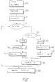
- Values of the load L and the number of revolutions RPM, defining an engine point, and an objective titre value ⁇ °, are initially set (block 100).
- the enrichment delay TR and the depletion delay TL are then set to zero (block 105) and the value of the inclination A needed to obtain the mean value of the control parameter K02 and the desired objective titre ⁇ ° are calculated (block 110).
- the inclination A is calculated in the manner described above.
- a test is then conducted to evaluate whether the absolute value of the inclination A calculated is lower than the threshold AS (block 115).
- the reference time unit is taken as the period between two successive instants in which a cylinder of the engine 2 is at the top dead centre, the enrichment delay TR is then rounded up to an entire multiple of the period between two successive top dead centres (block 140).
- the value of the inclination A is recalculated on the basis of the values of the enrichment delay TR and the depletion delay TL previously obtained (block 160).
- the method also provides a criterion for modifying the control action on the titre by acting at the same time on the integration and delay parameters.
- priority is in practice given to action on the inclination A (integration) and there is action on the enrichment delay TR and the depletion delay TL only to avoid excessive distortions of the wave shape of the correction parameter K02 (i.e. when the inclination A is greater, as an absolute value, than the threshold AS).
- the method makes it possible to set high deviations of the objective titre ⁇ from the unitary value, without significantly diminishing the frequency of oscillation of this titre about the objective value ⁇ °.
Landscapes
- Engineering & Computer Science (AREA)
- Chemical & Material Sciences (AREA)
- Combustion & Propulsion (AREA)
- Mechanical Engineering (AREA)
- General Engineering & Computer Science (AREA)
- Electrical Control Of Air Or Fuel Supplied To Internal-Combustion Engine (AREA)
- Testing Of Engines (AREA)
Abstract
Description
the method being characterised in that the selection stage is preceded by the stages of:
Claims (8)
- A method for controlling the titre of the exhaust gases in an internal combustion engine (2), in a control system (1) comprising a control unit (3) and oxygen sensor means (4), disposed along an exhaust duct (5) of the engine (2) and supplying a signal (Vλ) indicative of a titre (λ) of gases present in this exhaust duct (5), the control unit comprising memory means (8), controller means (9) and correction and actuation means (10), these memory means receiving as input a plurality of engine-related parameters (L, RPM) and an objective titre value (λ°) and supplying as output a plurality of operating parameters (TR, TL, A), the controller means (9) receiving as input the operating parameters (TR, TL, A) and the signal (Vλ) and supplying as output a correction parameter (K02) correlated with the operating parameters (TR, TL, A) and the signal (Vλ), the correction and actuation means (10) receiving as input a nominal quantity of fuel (QFN) and the correction parameter (KO2) and supplying as output to the engine (2) an adjusted quantity of fuel (QFR), the method comprising the stages of:a) selecting respective values of these operating parameters (A, TR, TL) on the basis of the objective titre value (λ°) and the engine-related parameters (L, RPM);b) calculating the correction parameter (KO2) on the basis of the respective values of the operating parameters (TR, TL, A) and the signal (Vλ ) ;c) calculating the adjusted quantity of fuel (QFR) on the basis of the correction parameter (K02) and the nominal quantity of fuel (QFN) ; the method being characterised in that the selection stage a) is preceded by the stages of:d) selecting (105) respective values of a first and a second of the operating parameters (TR, TL);e) calculating time magnitudes (TIL, TIR) as a function of a third of the operating parameters (A) in the presence of the respective selected values of the first and second operating parameters (TR, TL);f) determining (110) the third operating parameter (A) as a function of the first and second operating parameters selected (TR, TL) and a mean value of the correction parameter (KO2).
- A method as claimed in claim 1, characterised in that the stage e) comprises the stage of:
e1) determining a solution of the equation: - A method as claimed in claim 1 or 2, characterised in that it comprises the stages of:h) verifying (115) whether the third operating parameter (A) is lower than a predetermined threshold (AS);i) memorising (120) the first, second and third operating parameters, if the third operating parameter (A) is lower than the predetermined threshold (AS).
- A method as claimed in claim 3, characterised in that the stage h) of verifying (115) whether the third operating parameter (A) is lower than the predetermined threshold (AS), when this third operating parameter (A) is greater than this predetermined threshold (AS), is followed by the stages of:j) setting the third parameter (A) to the predetermined threshold (AS) if the objective titre value (λ°) is greater than 1 (125, 130);k) setting the third parameter (A) to a value opposite to the predetermined threshold (AS) if the objective titre value (λ°) is lower than 1 (125, 145).
- A method as claimed in claim 4, characterised in that the stage j) of setting the third parameter (A) to the predetermined threshold (AS) if the objective titre value (λ°) is greater than 1 (125, 130) is followed by the stages of:1) calculating (135) the first operating parameter (TR) as a function of the second and third operating parameters (TL, A);m) rounding this first operating parameter (TR) up to a multiple of a period between successive top dead centres (140).
- A method as claimed in claim 4 or 5, characterised in that the stage k) of setting the third parameter (A) to a value opposite to the predetermined threshold (AS) if the objective titre value (λ°) is lower than 1 (125, 145), is followed by the stages of:n) calculating (150) the second operating parameter (TL) as a function of the first and third operating parameters (TR, A);o) rounding this second operating parameter (TL) up to a multiple of a period between successive top dead centres (155).
- A method as claimed in claim 6, characterised in that it comprises the stage of:
p) re-calculating (160) this third operating parameter (A) as a function of the first and second operating parameters (TR, TL). - A method as claimed in claim 7, characterised in that the stage p) of re-calculating (160) this third operating parameter (A) is followed by the stage of
q) memorising these first, second and third operating parameters (TR, TL, A).
Applications Claiming Priority (2)
| Application Number | Priority Date | Filing Date | Title |
|---|---|---|---|
| IT2000BO000349A IT1321292B1 (en) | 2000-06-13 | 2000-06-13 | METHOD FOR CHECKING THE EXHAUST GAS TITLE IN AN INTERNAL COMBUSTION ENGINE. |
| ITBO000349 | 2000-06-13 |
Publications (2)
| Publication Number | Publication Date |
|---|---|
| EP1164275A1 true EP1164275A1 (en) | 2001-12-19 |
| EP1164275B1 EP1164275B1 (en) | 2005-02-09 |
Family
ID=11438541
Family Applications (1)
| Application Number | Title | Priority Date | Filing Date |
|---|---|---|---|
| EP01114228A Expired - Lifetime EP1164275B1 (en) | 2000-06-13 | 2001-06-12 | A method for controlling the titre of the exhaust gases in an internal combustion engine |
Country Status (6)
| Country | Link |
|---|---|
| US (1) | US6575152B2 (en) |
| EP (1) | EP1164275B1 (en) |
| BR (1) | BRPI0103122B1 (en) |
| DE (1) | DE60108810T2 (en) |
| ES (1) | ES2236088T3 (en) |
| IT (1) | IT1321292B1 (en) |
Families Citing this family (4)
| Publication number | Priority date | Publication date | Assignee | Title |
|---|---|---|---|---|
| US5865168A (en) * | 1997-03-14 | 1999-02-02 | Nellcor Puritan Bennett Incorporated | System and method for transient response and accuracy enhancement for sensors with known transfer characteristics |
| US20060196487A1 (en) * | 2005-03-01 | 2006-09-07 | Belton David N | Fuel control compensation for exhaust sensor response time degradation |
| DE102008018013B3 (en) * | 2008-04-09 | 2009-07-09 | Continental Automotive Gmbh | Method and device for operating an internal combustion engine |
| DE102011083781B3 (en) * | 2011-09-29 | 2012-05-24 | Continental Automotive Gmbh | Method for operating internal combustion engine, involves performing performance diagnosis of cylinders only in detection phase by introducing correction signal with proportional hop along with integral modified parameter into controller |
Citations (5)
| Publication number | Priority date | Publication date | Assignee | Title |
|---|---|---|---|---|
| US4210106A (en) * | 1975-10-13 | 1980-07-01 | Robert Bosch Gmbh | Method and apparatus for regulating a combustible mixture |
| US4461258A (en) * | 1980-10-18 | 1984-07-24 | Robert Bosch Gmbh | Regulating device for a fuel metering system of an internal combustion engine |
| US5492106A (en) * | 1994-12-27 | 1996-02-20 | Ford Motor Company | Jump-hold fuel control system |
| US5787867A (en) * | 1996-03-15 | 1998-08-04 | Robert Bosch Gmbh | Lambda control method |
| EP0952322A2 (en) * | 1994-07-19 | 1999-10-27 | MAGNETI MARELLI S.p.A. | Electronic air-fuel ratio control system for internal combustion engines |
Family Cites Families (2)
| Publication number | Priority date | Publication date | Assignee | Title |
|---|---|---|---|---|
| IT1308379B1 (en) * | 1999-02-19 | 2001-12-17 | Magneti Marelli Spa | METHOD OF SELF-ADAPTATION OF TITLE CONTROL IN AN INJECTION SYSTEM FOR AN INTERNAL COMBUSTION ENGINE. |
| IT1321203B1 (en) * | 2000-02-01 | 2003-12-31 | Magneti Marelli Spa | METHOD FOR CHECKING THE TITLE OF THE AIR - FUEL MIXTURE IN A COMBUSTION ENGINE. |
-
2000
- 2000-06-13 IT IT2000BO000349A patent/IT1321292B1/en active
-
2001
- 2001-06-12 DE DE60108810T patent/DE60108810T2/en not_active Expired - Lifetime
- 2001-06-12 BR BRPI0103122A patent/BRPI0103122B1/en not_active IP Right Cessation
- 2001-06-12 EP EP01114228A patent/EP1164275B1/en not_active Expired - Lifetime
- 2001-06-12 US US09/879,680 patent/US6575152B2/en not_active Expired - Lifetime
- 2001-06-12 ES ES01114228T patent/ES2236088T3/en not_active Expired - Lifetime
Patent Citations (5)
| Publication number | Priority date | Publication date | Assignee | Title |
|---|---|---|---|---|
| US4210106A (en) * | 1975-10-13 | 1980-07-01 | Robert Bosch Gmbh | Method and apparatus for regulating a combustible mixture |
| US4461258A (en) * | 1980-10-18 | 1984-07-24 | Robert Bosch Gmbh | Regulating device for a fuel metering system of an internal combustion engine |
| EP0952322A2 (en) * | 1994-07-19 | 1999-10-27 | MAGNETI MARELLI S.p.A. | Electronic air-fuel ratio control system for internal combustion engines |
| US5492106A (en) * | 1994-12-27 | 1996-02-20 | Ford Motor Company | Jump-hold fuel control system |
| US5787867A (en) * | 1996-03-15 | 1998-08-04 | Robert Bosch Gmbh | Lambda control method |
Also Published As
| Publication number | Publication date |
|---|---|
| DE60108810T2 (en) | 2006-01-12 |
| BRPI0103122B1 (en) | 2016-04-05 |
| EP1164275B1 (en) | 2005-02-09 |
| IT1321292B1 (en) | 2004-01-08 |
| US6575152B2 (en) | 2003-06-10 |
| BR0103122A (en) | 2002-02-13 |
| ES2236088T3 (en) | 2005-07-16 |
| DE60108810D1 (en) | 2005-03-17 |
| ITBO20000349A1 (en) | 2001-12-13 |
| US20020088447A1 (en) | 2002-07-11 |
Similar Documents
| Publication | Publication Date | Title |
|---|---|---|
| JP3161539B2 (en) | Method and apparatus for controlling air-fuel ratio of an internal combustion engine | |
| JPH06288276A (en) | Air-fuel ratio control device | |
| US6575152B2 (en) | Method for controlling the titre of the exhaust gases in an internal combustion engine | |
| US20070089720A1 (en) | Device for correcting fuel injection amount of internal combustion engine, and control apparatus for internal combustion engine employing the device | |
| EP0156356B1 (en) | Method for controlling the supply of fuel for an internal combustion engine | |
| JPH0979071A (en) | Air-fuel ratio learning controller for internal combustion engine | |
| JPH07279729A (en) | In-cylinder injection fuel control device for internal combustion engine | |
| JP2539506B2 (en) | Air-fuel ratio controller for electronically controlled fuel injection engine | |
| JP3899658B2 (en) | Exhaust gas purification device for internal combustion engine | |
| KR100187783B1 (en) | Engine control apparatus | |
| JP3460354B2 (en) | Air-fuel ratio control device for internal combustion engine | |
| JPH10331695A (en) | Control device for internal combustion engine | |
| US5653104A (en) | Engine air/fuel control system with adaptively alignment of a catalytic converter's peak efficiency window | |
| JPH0455235Y2 (en) | ||
| JP2000213396A (en) | Air-fuel ratio control device for internal combustion engine | |
| JPH077564Y2 (en) | Air-fuel ratio learning controller for internal combustion engine | |
| JPH0740673Y2 (en) | Air-fuel ratio learning controller for internal combustion engine | |
| JP4888365B2 (en) | Air-fuel ratio control device for internal combustion engine | |
| JP2712086B2 (en) | Air-fuel ratio control method for internal combustion engine | |
| JP4254520B2 (en) | Engine air-fuel ratio control device | |
| JP2631580B2 (en) | Air-fuel ratio learning control device for internal combustion engine | |
| JP2019060346A (en) | Air-fuel ratio control device and air-fuel ratio control method of internal combustion engine | |
| JPH0423099B2 (en) | ||
| JPS6270641A (en) | Internal combustion engine learning control device | |
| JPS62210234A (en) | Air-fuel ratio control method |
Legal Events
| Date | Code | Title | Description |
|---|---|---|---|
| PUAI | Public reference made under article 153(3) epc to a published international application that has entered the european phase |
Free format text: ORIGINAL CODE: 0009012 |
|
| AK | Designated contracting states |
Kind code of ref document: A1 Designated state(s): AT BE CH CY DE DK ES FI FR GB GR IE IT LI LU MC NL PT SE TR Kind code of ref document: A1 Designated state(s): DE ES FR GB SE |
|
| AX | Request for extension of the european patent |
Free format text: AL;LT;LV;MK;RO;SI |
|
| 17P | Request for examination filed |
Effective date: 20020604 |
|
| AKX | Designation fees paid |
Free format text: DE ES FR GB SE |
|
| 17Q | First examination report despatched |
Effective date: 20040210 |
|
| GRAP | Despatch of communication of intention to grant a patent |
Free format text: ORIGINAL CODE: EPIDOSNIGR1 |
|
| GRAS | Grant fee paid |
Free format text: ORIGINAL CODE: EPIDOSNIGR3 |
|
| RAP1 | Party data changed (applicant data changed or rights of an application transferred) |
Owner name: MAGNETI MARELLI POWERTRAIN S.P.A. |
|
| GRAA | (expected) grant |
Free format text: ORIGINAL CODE: 0009210 |
|
| AK | Designated contracting states |
Kind code of ref document: B1 Designated state(s): DE ES FR GB SE |
|
| REG | Reference to a national code |
Ref country code: GB Ref legal event code: FG4D |
|
| REG | Reference to a national code |
Ref country code: IE Ref legal event code: FG4D |
|
| REF | Corresponds to: |
Ref document number: 60108810 Country of ref document: DE Date of ref document: 20050317 Kind code of ref document: P |
|
| REG | Reference to a national code |
Ref country code: SE Ref legal event code: TRGR |
|
| REG | Reference to a national code |
Ref country code: ES Ref legal event code: FG2A Ref document number: 2236088 Country of ref document: ES Kind code of ref document: T3 |
|
| PLBE | No opposition filed within time limit |
Free format text: ORIGINAL CODE: 0009261 |
|
| STAA | Information on the status of an ep patent application or granted ep patent |
Free format text: STATUS: NO OPPOSITION FILED WITHIN TIME LIMIT |
|
| ET | Fr: translation filed | ||
| 26N | No opposition filed |
Effective date: 20051110 |
|
| PGFP | Annual fee paid to national office [announced via postgrant information from national office to epo] |
Ref country code: ES Payment date: 20090616 Year of fee payment: 9 |
|
| PGFP | Annual fee paid to national office [announced via postgrant information from national office to epo] |
Ref country code: SE Payment date: 20090625 Year of fee payment: 9 |
|
| PGFP | Annual fee paid to national office [announced via postgrant information from national office to epo] |
Ref country code: GB Payment date: 20090617 Year of fee payment: 9 |
|
| EUG | Se: european patent has lapsed | ||
| GBPC | Gb: european patent ceased through non-payment of renewal fee |
Effective date: 20100612 |
|
| REG | Reference to a national code |
Ref country code: ES Ref legal event code: FD2A Effective date: 20110714 |
|
| PG25 | Lapsed in a contracting state [announced via postgrant information from national office to epo] |
Ref country code: ES Free format text: LAPSE BECAUSE OF NON-PAYMENT OF DUE FEES Effective date: 20110704 Ref country code: GB Free format text: LAPSE BECAUSE OF NON-PAYMENT OF DUE FEES Effective date: 20100612 |
|
| PG25 | Lapsed in a contracting state [announced via postgrant information from national office to epo] |
Ref country code: ES Free format text: LAPSE BECAUSE OF NON-PAYMENT OF DUE FEES Effective date: 20100613 |
|
| PG25 | Lapsed in a contracting state [announced via postgrant information from national office to epo] |
Ref country code: SE Free format text: LAPSE BECAUSE OF NON-PAYMENT OF DUE FEES Effective date: 20100613 |
|
| REG | Reference to a national code |
Ref country code: FR Ref legal event code: PLFP Year of fee payment: 15 |
|
| REG | Reference to a national code |
Ref country code: FR Ref legal event code: PLFP Year of fee payment: 16 |
|
| REG | Reference to a national code |
Ref country code: FR Ref legal event code: PLFP Year of fee payment: 17 |
|
| REG | Reference to a national code |
Ref country code: FR Ref legal event code: PLFP Year of fee payment: 18 |
|
| PGFP | Annual fee paid to national office [announced via postgrant information from national office to epo] |
Ref country code: FR Payment date: 20200520 Year of fee payment: 20 Ref country code: DE Payment date: 20200519 Year of fee payment: 20 |
|
| REG | Reference to a national code |
Ref country code: DE Ref legal event code: R071 Ref document number: 60108810 Country of ref document: DE |