EP1163876A1 - Interface unit for an electrophysiological measurement system - Google Patents
Interface unit for an electrophysiological measurement system Download PDFInfo
- Publication number
- EP1163876A1 EP1163876A1 EP01102518A EP01102518A EP1163876A1 EP 1163876 A1 EP1163876 A1 EP 1163876A1 EP 01102518 A EP01102518 A EP 01102518A EP 01102518 A EP01102518 A EP 01102518A EP 1163876 A1 EP1163876 A1 EP 1163876A1
- Authority
- EP
- European Patent Office
- Prior art keywords
- interface unit
- unit
- individual
- indication
- overlay
- Prior art date
- Legal status (The legal status is an assumption and is not a legal conclusion. Google has not performed a legal analysis and makes no representation as to the accuracy of the status listed.)
- Withdrawn
Links
Images



Classifications
-
- A—HUMAN NECESSITIES
- A61—MEDICAL OR VETERINARY SCIENCE; HYGIENE
- A61B—DIAGNOSIS; SURGERY; IDENTIFICATION
- A61B5/00—Measuring for diagnostic purposes; Identification of persons
- A61B5/24—Detecting, measuring or recording bioelectric or biomagnetic signals of the body or parts thereof
- A61B5/30—Input circuits therefor
- A61B5/303—Patient cord assembly, e.g. cable harness
Definitions
- the present invention relates to an interface unit for an electrophysiological measurement system which allows electrical connections to be established between wires from catheter mounted electrodes and a monitoring system in a variable manner and in particular to a unit which includes a display means for displaying a connection configuration.
- Electrophysiological measurement systems generally comprise a monitoring system for one or more of receiving, storing, processing and displaying signals from a number of patient interactive elements such as catheter mounted intracardiac electrodes, surface ECG electrodes, blood parameter sensors, and like physiological parameter sensors; and an interface unit.
- the monitoring system often includes a switching unit by which measurements may be selectively made using different combinations intracardiac electrodes.
- the interface unit is typically provided bedside to receive the proximal ends of wires which are connected at their distal ends to the patient interactive elements and provide for their electrical connection to the switching unit of the monitoring system.
- the wires are received by the interface unit in releasable engagement with input terminals which, for the intracardiac electrodes, are often arranged at the outer surface of the unit in a grid fashion.
- An output socket is provided for electrical connection to the switching unit and comprises contacts, each of which are in fixed connection with a corresponding input terminal. Which electrode wire connects to which terminal is dependent largely on the combination of catheters being used for a particular physiological study, the nature of that study and how the monitoring system is configured to receive the electrical signals.
- each terminal is permanently labelled in numerical sequence for identification purposes.
- Each wire of a particular catheter is usually provided with an identifying label by the manufacturer.
- Look-up tables can be constructed using these two sets of labels to indicate the wire/terminal configuration required for a particular study.
- a wipe-clean surface may be available on the interface unit so that a label can be provided for each terminal used in the study which identifies the catheter electrode wire to be inserted according to the look-up table.
- each overlay of the library may be retained on and possibly moveable over binding posts which are attached to the housing of the interface unit. This arrangement helps maintain the integrity of the library and can aid the correlation of the overlay with the upper surface of the housing.
- each overlay is constructed so that contacts for each catheter of a catheter combination are grouped together with the visible indication preferably including a visible demarcation, such as a lined or coloured/shaded block demarcation or an inter-connecting line demarcation, of the different groups of contacts; an identifier to visibly link an individual catheter to a particular contact grouping, for example a label or colour code identifier; and wire label identifiers which preferably correspond to the catheter manufacturer provided wire identifiers.
- a readily interpretable indication of the expected wire/contact configuration is provide in a single overlay without having to memorise or record often complex and abstract "artificial" label identifiers.
- This grouping and labelling arrangement may also be similarly advantageously employed with other display means such as an LCD screen display or a permanently fixed display.
- Fig. 1 is a representation of an interface unit according to the present invention
- Figs. 2 a) and b) show representations of overlay cards for use with an interface unit according to the present invention.
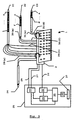
- Fig. 3 is a schematic diagram illustrating the components of a electrophysiological measuring system having an interface unit according to the present invention.
- Fig. 4 is a schematic diagram illustrating an alternative electrophysiological measuring system.
- a housing 2 has on an outer surface 3 a plurality of jacks (shown generally at 4) arranged grid-wise, for example thirty two jacks arranged in a four-by-eight matrix as illustrated, and two further jacks 5. These jacks 4,5 provide for a releasable engagement with complementary jack plugs of intracardiac catheter electrode wires (not shown).
- a standard "D-connector" 6 and two jacks 7 are provided in a side-wall 8 of the housing 2 and are made in hard-wired connection within the housing 2 to respectively the grid-wise arranged jacks 4 and the two other jack 5 within the housing 2.
- the D-connector 6 may be provided with connections to the two further jacks 5 and the jacks 7 in the side-wall 8 omitted.
- the D-connector 6 may be replaced by a multi-core wire which is permanently connected to the jacks 4,5.
- a number of overlays 9-11 are also releasably connected to the housing 2 by means of ring-binders 12 and are provided with a plurality of holes (shown generally at 13) which, when an overlay 9 is correctly located on the surface 3, correspond with the jacks 4,5 to permit their electrical connection with catheter wires.
- Each overlay 9-11 can be moved on or removed from the ring-binders 12 between a position (overlays 10-11) away from the outer surface 3 and a position (overlay 9) on the surface 3 in which it overlays the jacks 4,5.
- Each overlay 9-11 has on an upper face 14 (when positioned on the outer surface 3 of the housing 2) a visible indication of different wire/jack 4 inter-connections necessary to allow a particular electrophysiological study to be undertaken using a particular catheter combination, as will be described more fully below in relation to Fig. 3.
- Each overlay 9-11 may be provided with an identification label 15 (see Figs.2) by which a user can confirm that the correct overlay 9-11 is placed uppermost on the surface 3 of the housing 2.
- the overlay 9 here comprises a thin, flexible sheet of, for example, acetate or other plastic, through which a plurality of holes 13 have been made, each one disposed so that it allows access to a corresponding one of the jacks 4,5 when the overlay 9 is located on the outer surface 3 of the housing 2.
- a visible indication is provided to guide the inter-connection of wire and jack 4 for a particular combination of catheters (here three catheters, one with twelve wires, one with six and one with four).
- This indication may comprise one or both opaque blocks 16,18, and boundary demarcation line 17 arranged on the face 14 to provide a visible demarcation between jacks for different catheters.
- Each indication 16,17,18 has a catheter label area 16a,17a,18a on which a catheter identifier is provided.
- the identifier may, for example, be selected from the well known "RA", "RV” etc. notations which clinicians use to indicate locations within the heart and so provides an intuitive indication of which catheter to connect.
- Each indication 16,17,18 also has wire label areas (shown generally at 16b,17b,18b but not necessarily having visible boundaries)on which wire identifiers, for example numerals "1,2,3" corresponding to the manufacturer provided designations, are provided with each one in registration with an individual hole 13.
- An indication block 19 is also provided which acts to delimit the non-grid jacks 5 which are provided specifically to accept jack plugs from stimulation electrodes and are labelled "S+” and "S-" (identifying the polarity of the stimulation pulse).
- Each overlay is provided in the block 20 with the unique identifying label 15, such as an alphanumeric "A1".
- this arrangement provides a visible indication by which catheter leads from different catheter combinations can be readily and intuitively linked with the correct jack 4 since the grouping of jacks for each catheter is clearly shown by the indications 16,17,18 and since for each catheter the wire labels 16b,17b,18b preferably correspond to the labels placed on individual wires by the manufacturer.
- FIG. 2b An alternative overlay 9 is shown in Fig. 2b in which indication block 16,17,18 is replaced by a corresponding inter-connecting line 16',17',18'. Each line 16',17'18' is arranged to inter-connect a different combination of the holes 13 in order to differentiate the individual catheter contact groupings.
- the catheter label areas 16'a,17'a and 18'a, which correspond to the label areas 16a,17a,18a of the overlay 9 of Fig. 2a are shown linked to their respective lines 16',17',18' by a connecting line.
- the overlay identifier label 15 is again placed within the block.
- overlays 9-11 may be better understood from a description of the operation of the electrophysiological measurement system of Fig.3, in which is shown three intracardiac measurement catheters 21,22,23 and one intracardiac stimulation catheter 24 in electrical connection to jacks 4,5(Fig. 1) in the housing 2 of the interface unit 1; and an electrophysiological monitoring system 25 electrically connected to the jacks 4,5 via the D-connection 6 (Fig. 1) and the input jacks 7 (Fig. 1) by respective wires 26 and 27,28.
- a number of measurement electrodes 21a-l; 22a-f and 23a-d are located on the respective catheters 21,22,23 for insertion into the heart and are connected to a corresponding number of wires 29a-l; 30a-f; 31a-d.
- These wires 29a-1; 30a-f; 31a-d are provided at their free ends with jack plugs (not shown) for releasable connection with the jacks 4 (Fig. 1) of the interface unit 1 and are labelled in numerical sequence starting at one (or sometimes "d” as shown in Fig. 2b) for each of the catheters 21-23.
- the monitoring system 25 includes a switching unit 32; a stimulation unit 33; an amplifier unit 34; a processing/control unit 35; a display monitor 36 and a user input interface 37.
- a switching unit 32 for example, a switching unit 32; a stimulation unit 33; an amplifier unit 34; a processing/control unit 35; a display monitor 36 and a user input interface 37.
- these units are typically found in known electrophysiological monitoring systems where other components may also be found, such as a printer, a remote communications unit and the like and which items are not intended to be excluded from the system 25 of the present example.
- each unit 32-37 is illustrated as being a separate item it is well known that the functionality of some or all of the individual units may be provided in a single physical unit such as a suitably configured and programmed personal computer or a dedicated microprocessor unit.
- the wire 26 provides electrical connections between the individual jacks 4 of the interface unit 1 and individual input channels of the switching unit 32.
- the unit 32 comprises electrically actuated switches (not show) which can be open and closed in an optional manner by control signals passed from the processing/control unit 35 so as to allow for electrophysiological measurements to be made within the processing/control unit 25, using selected combinations of electrodes of the connected catheters 21-23.
- switches not show
- the processing/control unit 35 also includes a storage device, such as a computer hard disc, on which is stored a plurality of predefined switch arrangements, each linked with a different one or more expected wire/jack configurations, and an indication of the electrophysiological measurements performed by a particular configuration/arrangement combination.
- a storage device such as a computer hard disc, on which is stored a plurality of predefined switch arrangements, each linked with a different one or more expected wire/jack configurations, and an indication of the electrophysiological measurements performed by a particular configuration/arrangement combination. This information may be stored by the manufacturer of the equipment and additionally or alternatively may be added by a user during a system set-up procedure outlined below.
- an overlay card 9-11 (Fig. 1) is provided at the interface unit 1 with a visible indication of the particular configuration, as described above in relation to Fig. 1 and Figs. 2a,b, on a face 14.
- the monitoring system 25 is configured to operate so the user may indicate on the display monitor 36, using the user input interface 37, such as an alpha-numeric keyboard or mouse, a particular electrophysiological study and a particular catheter combination (of course if one or other of these parameters is fixed then only the variable one need by indicated).
- the processing/control unit 35 processes the choice and selects the overlay 9-11 which provides the particular wire/jack combination needed to fulfil the choice.
- a visible indication of the particular overlay 9-11 (Fig. 1) which provides this combination is generated on the display screen 36 by the unit 35.
- This indication may be the identifier label 15 (Figs. 2) of an overlay 9 or could additionally or alternatively be a graphical image depicting the upper surface 14 of the necessary overlay.
- the overlays 9-11 on the ring binders 13 are flipped through and the correct overlay is placed uppermost on the surface 3 of the interface unit housing 2 (Fig. 1).
- Catheter wires 29(a-l), 30(a-f), 31(a-d) are then inserted according to the indications on the overlay surface 14.
- a set-up routine within the processing/control unit 35 enables a user to define the switch arrangement to be employed in the switching unit 32 and also the catheter wire/interface unit contact arrangement, if this is new.
- the processing/control unit 35 then adds the new switch arrangement to the store of existing arrangements with a link to a different one or more expected wire/jack configurations and with an indication of the electrophysiological measurements performed by a particular configuration/arrangement combination.
- the user may be presented with an image on the display screen 36 illustrating a blank overlay and prompted to input, using the user input interface 37, the number of catheters and their number of wires (optionally with the manufacturers own wire identification labels).
- the processing/control unit 35 can be programmed to calculate and display a suitable catheter arrangement on the blank overlay in which the wires for each catheter are grouped together and in which a visible demarcation is provided on a new overlay to indicate the separate catheter groupings.
- the user may be permitted to form these groupings manually on the screen image of the overlay.
- the user provides identifying labels as well as wire indicators, which in default are a number sequence typically used by catheter manufacturers as wire identifiers.
- identifying labels and wire indicators are presented on the screen image in regions corresponding to catheter label areas 16a,17a,18a; 16'a,17'a,18'a and wire label areas 16b,17b,18b; 16'b,17'b,18'b on the actual overlay 9 (Figs. 2).
- the user indicates acceptance of the overlay layout presented on the screen 36 using the interface 37 and provides a unique overlay identifying label 15 which is entered on the screen image in the region corresponding to the identifier block 20 (Figs. 2) on the actual overlay 9.
- this label 15 may be generated by the processing/control unit 35.
- the processing/control unit 35 then processes this screen image to provide printer control commands for use by an optional printer (not shown), such as a conventional ink-jet or laser printer, which prints the image on a blank overlay sheet that for convenience may be pre-formed with the through holes 13 (Figs. 2).
- an optional printer such as a conventional ink-jet or laser printer, which prints the image on a blank overlay sheet that for convenience may be pre-formed with the through holes 13 (Figs. 2).
- FIG. 4 an alternative electrophysiological measurement system is shown in which elements corresponding to elements shown in the system of Fig. 3 and the interface unit of Fig. 1 are given corresponding reference numerals.
- a switch unit 32 of a monitoring system 25 is connected via signal cables 26a, 26b to two interface units 38a, 38b, each of which unit is intended to interface with a different combination of catheters necessary to carry out an electrophysiological study.
- Each interface unit 38a, 38b is similar in configuration to the interface unit of Fig 1 and comprises a number, shown here as twenty four, input jacks 4a,4b arranged in a grid, here a eight-by-three matrix, on an outer surface 3a, 3b.
- Dedicated stimulation catheter jacks 5a,5b are also provided in this surface 3a,3b and all jacks 4,5 are hard wired respectively to D-connectors 6a,6b and to further jacks 7a,7b. These further jacks 7a,7b are available for releasable connection with input wires 27,28 of a stimulator unit 33 which is controlled by a processing/control unit 35 to provide electrical signals useable to stimulate activity in a heart during a study.
- Each interface unit 38a,38b has formed on the surface 3a,3b containing the jacks 4a,4b a permanent visible indication of the wire/contact configuration for a particular combination of catheters (here illustrated as three for each unit).
- This indication is essentially that described above in respect of the overlay of Fig. 2 and includes a visible demarcation between groupings of jacks 4 for the different catheters.
- This demarcation may be, for example, in the form of coloured or shaded regions 39,40,41 or simply line markings 42,43,44 about the periphery of each grouping.
- labels 20a, 20b which may be used to identify the particular interface box 38a, 38b to the user and to the monitoring system 25.
- the interface unit may be modified to additionally receive input wires from other patient interactive elements (ECG wires, pressure sensors and blood gas sensors, for example) and may be provided with a different number of contacts within the grid arrangement without departing from the scope of the invention as claimed.
- ECG wires ECG wires, pressure sensors and blood gas sensors, for example
Landscapes
- Life Sciences & Earth Sciences (AREA)
- Health & Medical Sciences (AREA)
- Medical Informatics (AREA)
- Biophysics (AREA)
- Pathology (AREA)
- Engineering & Computer Science (AREA)
- Biomedical Technology (AREA)
- Heart & Thoracic Surgery (AREA)
- Physics & Mathematics (AREA)
- Molecular Biology (AREA)
- Surgery (AREA)
- Animal Behavior & Ethology (AREA)
- General Health & Medical Sciences (AREA)
- Public Health (AREA)
- Veterinary Medicine (AREA)
- Measurement And Recording Of Electrical Phenomena And Electrical Characteristics Of The Living Body (AREA)
- Measuring And Recording Apparatus For Diagnosis (AREA)
Abstract
Description
- The present invention relates to an interface unit for an electrophysiological measurement system which allows electrical connections to be established between wires from catheter mounted electrodes and a monitoring system in a variable manner and in particular to a unit which includes a display means for displaying a connection configuration.
- Electrophysiological measurement systems generally comprise a monitoring system for one or more of receiving, storing, processing and displaying signals from a number of patient interactive elements such as catheter mounted intracardiac electrodes, surface ECG electrodes, blood parameter sensors, and like physiological parameter sensors; and an interface unit. The monitoring system often includes a switching unit by which measurements may be selectively made using different combinations intracardiac electrodes.
- The interface unit is typically provided bedside to receive the proximal ends of wires which are connected at their distal ends to the patient interactive elements and provide for their electrical connection to the switching unit of the monitoring system. The wires are received by the interface unit in releasable engagement with input terminals which, for the intracardiac electrodes, are often arranged at the outer surface of the unit in a grid fashion. An output socket is provided for electrical connection to the switching unit and comprises contacts, each of which are in fixed connection with a corresponding input terminal. Which electrode wire connects to which terminal is dependent largely on the combination of catheters being used for a particular physiological study, the nature of that study and how the monitoring system is configured to receive the electrical signals.
- Before undertaking any physiological study the system must be set-up so that the correct catheter wires are connected with the correct terminals on the interface unit. To facilitate this set-up it is known to provide an interface unit wherein each terminal is permanently labelled in numerical sequence for identification purposes. Each wire of a particular catheter is usually provided with an identifying label by the manufacturer. Look-up tables can be constructed using these two sets of labels to indicate the wire/terminal configuration required for a particular study. A wipe-clean surface may be available on the interface unit so that a label can be provided for each terminal used in the study which identifies the catheter electrode wire to be inserted according to the look-up table. However, very often during a physiology study, it is desirable to either move a catheter to a different measurement location, to alter the combination of catheters, or to re-define the measurement protocol for the same catheter combination. In any of these events, it is necessary to re-configure the interface unit connections and in the process replace the particular labels on the interface unit to correspond with the new configuration. This can be tedious and time-consuming for the operator and may lead to an incorrect configuration being made during the two step process of identifying the correct look-up table and then transferring the tabulated assignments to visible labels on the interface unit.
- To alleviate this problem it is known from US 5,640,967 to provide an "intelligent" device which combines switching, amplification and interface functions in a single, compact bed-side unit. A microprocessor controlled LCD screen display is provided to graphically display the connection configuration required for a particular measurement protocol. A memory is also provided for storing a library of different configurations for later retrieval and display.
- With the additional electronic components this is relatively expensive to implement compared with the existing "dumb" interface unit in which essentially only the releasable connections between wires and terminals are selectively established (the connections between each terminal and a corresponding output pin of the unit remains fixed). Moreover, the use of an LCD display does not in itself address the problem of the construction of readily interpretable labels.
- An additional problem can result from the manufacturer's normal practice of labelling the wires connecting each electrode of a particular catheter in numerical order when trying to establish the correct electrode wire connection at the interface unit since each catheter in a combination of catheters will contain identically identified wires. Labels in this circumstance cannot be easily constructed which provide for an intuitive (and thus inherently safer) correlation between wire and terminal.
- By providing an interface unit disclosed in and characterised by the present claim 1 a library of wire/contact configurations can be established relatively inexpensively and without the addition of complex electronic components to provide a unit in which the visual portrayal of wire/catheter combinations can be readily varied.
- Usefully, each overlay of the library may be retained on and possibly moveable over binding posts which are attached to the housing of the interface unit. This arrangement helps maintain the integrity of the library and can aid the correlation of the overlay with the upper surface of the housing.
- Preferably each overlay is constructed so that contacts for each catheter of a catheter combination are grouped together with the visible indication preferably including a visible demarcation, such as a lined or coloured/shaded block demarcation or an inter-connecting line demarcation, of the different groups of contacts; an identifier to visibly link an individual catheter to a particular contact grouping, for example a label or colour code identifier; and wire label identifiers which preferably correspond to the catheter manufacturer provided wire identifiers. In this manner a readily interpretable indication of the expected wire/contact configuration is provide in a single overlay without having to memorise or record often complex and abstract "artificial" label identifiers. This grouping and labelling arrangement may also be similarly advantageously employed with other display means such as an LCD screen display or a permanently fixed display.
- Exemplary embodiments of the present invention will now be described with reference to the drawings of the accompanying figures of which:
- Fig. 1 is a representation of an interface unit according to the present invention
- Figs. 2 a) and b) show representations of overlay cards for use with an interface unit according to the present invention.
- Fig. 3 is a schematic diagram illustrating the components of a electrophysiological measuring system having an interface unit according to the present invention.
- Fig. 4 is a schematic diagram illustrating an alternative electrophysiological measuring system.
- Considering now the
interface unit 1 of Fig. 1, ahousing 2 has on anouter surface 3 a plurality of jacks (shown generally at 4) arranged grid-wise, for example thirty two jacks arranged in a four-by-eight matrix as illustrated, and twofurther jacks 5. Thesejacks jacks 7 are provided in a side-wall 8 of thehousing 2 and are made in hard-wired connection within thehousing 2 to respectively the grid-wise arrangedjacks 4 and the twoother jack 5 within thehousing 2. Alternatively, the D-connector 6 may be provided with connections to the twofurther jacks 5 and thejacks 7 in the side-wall 8 omitted. Moreover, the D-connector 6 may be replaced by a multi-core wire which is permanently connected to thejacks - A number of overlays 9-11 are also releasably connected to the
housing 2 by means of ring-binders 12 and are provided with a plurality of holes (shown generally at 13) which, when anoverlay 9 is correctly located on thesurface 3, correspond with thejacks binders 12 between a position (overlays 10-11) away from theouter surface 3 and a position (overlay 9) on thesurface 3 in which it overlays thejacks outer surface 3 of the housing 2) a visible indication of different wire/jack 4 inter-connections necessary to allow a particular electrophysiological study to be undertaken using a particular catheter combination, as will be described more fully below in relation to Fig. 3. Each overlay 9-11 may be provided with an identification label 15 (see Figs.2) by which a user can confirm that the correct overlay 9-11 is placed uppermost on thesurface 3 of thehousing 2. - Considering now Fig. 2a, an example of an
overlay 9 useable with theinterface unit 1 of Fig. 1 is illustrated. Theoverlay 9 here comprises a thin, flexible sheet of, for example, acetate or other plastic, through which a plurality ofholes 13 have been made, each one disposed so that it allows access to a corresponding one of thejacks overlay 9 is located on theouter surface 3 of thehousing 2. On oneface 14 of the sheet a visible indication is provided to guide the inter-connection of wire andjack 4 for a particular combination of catheters (here three catheters, one with twelve wires, one with six and one with four). - This indication may comprise one or both
opaque blocks boundary demarcation line 17 arranged on theface 14 to provide a visible demarcation between jacks for different catheters. Eachindication catheter label area - Each
indication individual hole 13. Anindication block 19 is also provided which acts to delimit thenon-grid jacks 5 which are provided specifically to accept jack plugs from stimulation electrodes and are labelled "S+" and "S-" (identifying the polarity of the stimulation pulse). Each overlay is provided in theblock 20 with the unique identifyinglabel 15, such as an alphanumeric "A1". Thus, as can be appreciated from a consideration of the illustration of theoverlay 9 presented in Fig. 2a, this arrangement provides a visible indication by which catheter leads from different catheter combinations can be readily and intuitively linked with thecorrect jack 4 since the grouping of jacks for each catheter is clearly shown by theindications wire labels - An
alternative overlay 9 is shown in Fig. 2b in whichindication block holes 13 in order to differentiate the individual catheter contact groupings. The catheter label areas 16'a,17'a and 18'a, which correspond to thelabel areas overlay 9 of Fig. 2a are shown linked to their respective lines 16',17',18' by a connecting line. Theoverlay identifier label 15 is again placed within the block. - Indeed these unique and inventive visible indications, here shown on the
surfaces 14 of theremovable overlays 9 of Figs. 2a and 2b, may be provided as a permanently fixed display marked on the surface of ahousing 2 similar to theinterface unit 1 of Fig. 1 or even displayed using an integral, preferably flat panel, display screen (not shown). - The selection and construction of these overlays 9-11 may be better understood from a description of the operation of the electrophysiological measurement system of Fig.3, in which is shown three
intracardiac measurement catheters intracardiac stimulation catheter 24 in electrical connection tojacks 4,5(Fig. 1) in thehousing 2 of theinterface unit 1; and anelectrophysiological monitoring system 25 electrically connected to thejacks respective wires respective catheters interface unit 1 and are labelled in numerical sequence starting at one (or sometimes "d" as shown in Fig. 2b) for each of the catheters 21-23. - The
monitoring system 25 includes aswitching unit 32; astimulation unit 33; anamplifier unit 34; a processing/control unit 35; adisplay monitor 36 and auser input interface 37. It will be appreciated by those skilled in the art that that these units are typically found in known electrophysiological monitoring systems where other components may also be found, such as a printer, a remote communications unit and the like and which items are not intended to be excluded from thesystem 25 of the present example. Moreover, whereas, for ease of reference and understanding, each unit 32-37 is illustrated as being a separate item it is well known that the functionality of some or all of the individual units may be provided in a single physical unit such as a suitably configured and programmed personal computer or a dedicated microprocessor unit. - The
wire 26 provides electrical connections between theindividual jacks 4 of theinterface unit 1 and individual input channels of the switchingunit 32. Theunit 32 comprises electrically actuated switches (not show) which can be open and closed in an optional manner by control signals passed from the processing/control unit 35 so as to allow for electrophysiological measurements to be made within the processing/control unit 25, using selected combinations of electrodes of the connected catheters 21-23. Thus it can be seen that for a particular arrangement of open and closed switches the measurements made will depend on the wire/jack configuration at theinterface unit 1. - The processing/
control unit 35 also includes a storage device, such as a computer hard disc, on which is stored a plurality of predefined switch arrangements, each linked with a different one or more expected wire/jack configurations, and an indication of the electrophysiological measurements performed by a particular configuration/arrangement combination. This information may be stored by the manufacturer of the equipment and additionally or alternatively may be added by a user during a system set-up procedure outlined below. - For each different wire/jack configuration an overlay card 9-11 (Fig. 1) is provided at the
interface unit 1 with a visible indication of the particular configuration, as described above in relation to Fig. 1 and Figs. 2a,b, on aface 14. Themonitoring system 25 is configured to operate so the user may indicate on thedisplay monitor 36, using theuser input interface 37, such as an alpha-numeric keyboard or mouse, a particular electrophysiological study and a particular catheter combination (of course if one or other of these parameters is fixed then only the variable one need by indicated). The processing/control unit 35 processes the choice and selects the overlay 9-11 which provides the particular wire/jack combination needed to fulfil the choice. A visible indication of the particular overlay 9-11 (Fig. 1) which provides this combination is generated on thedisplay screen 36 by theunit 35. This indication may be the identifier label 15 (Figs. 2) of anoverlay 9 or could additionally or alternatively be a graphical image depicting theupper surface 14 of the necessary overlay. The overlays 9-11 on thering binders 13 are flipped through and the correct overlay is placed uppermost on thesurface 3 of the interface unit housing 2 (Fig. 1). Catheter wires 29(a-l), 30(a-f), 31(a-d) are then inserted according to the indications on theoverlay surface 14. - If the electrophysiological study or the particular catheter combination is new then a set-up routine within the processing/
control unit 35 enables a user to define the switch arrangement to be employed in theswitching unit 32 and also the catheter wire/interface unit contact arrangement, if this is new. The processing/control unit 35 then adds the new switch arrangement to the store of existing arrangements with a link to a different one or more expected wire/jack configurations and with an indication of the electrophysiological measurements performed by a particular configuration/arrangement combination. - When defining a new wire/contact arrangement the user may be presented with an image on the
display screen 36 illustrating a blank overlay and prompted to input, using theuser input interface 37, the number of catheters and their number of wires (optionally with the manufacturers own wire identification labels). The processing/control unit 35 can be programmed to calculate and display a suitable catheter arrangement on the blank overlay in which the wires for each catheter are grouped together and in which a visible demarcation is provided on a new overlay to indicate the separate catheter groupings. Alternatively, the user may be permitted to form these groupings manually on the screen image of the overlay. When the groupings have been formed the user provides identifying labels as well as wire indicators, which in default are a number sequence typically used by catheter manufacturers as wire identifiers. These identifying labels and wire indicators are presented on the screen image in regions corresponding tocatheter label areas wire label areas screen 36 using theinterface 37 and provides a uniqueoverlay identifying label 15 which is entered on the screen image in the region corresponding to the identifier block 20 (Figs. 2) on theactual overlay 9. Alternatively, thislabel 15 may be generated by the processing/control unit 35. The processing/control unit 35 then processes this screen image to provide printer control commands for use by an optional printer (not shown), such as a conventional ink-jet or laser printer, which prints the image on a blank overlay sheet that for convenience may be pre-formed with the through holes 13 (Figs. 2). - Considering now Fig. 4, an alternative electrophysiological measurement system is shown in which elements corresponding to elements shown in the system of Fig. 3 and the interface unit of Fig. 1 are given corresponding reference numerals. A
switch unit 32 of amonitoring system 25 is connected viasignal cables interface units interface unit input jacks outer surface stimulation catheter jacks surface jacks connectors further jacks further jacks input wires stimulator unit 33 which is controlled by a processing/control unit 35 to provide electrical signals useable to stimulate activity in a heart during a study. - Each
interface unit surface jacks jacks 4 for the different catheters. This demarcation may be, for example, in the form of coloured or shadedregions markings surfaces labels particular interface box monitoring system 25. - Whereas the above embodiments of the interface unit according to the present invention have been described solely in relation to intracardiac catheter electrodes it will be appreciated by those skilled in the art that the interface unit may be modified to additionally receive input wires from other patient interactive elements (ECG wires, pressure sensors and blood gas sensors, for example) and may be provided with a different number of contacts within the grid arrangement without departing from the scope of the invention as claimed.
Claims (12)
- An interface unit (1) for establishing an electrical coupling of a plurality of sensor wires (29a-1;30a-f;31a-d) from a combination of catheters (21;22;23) with a plurality of electrical signal channels of a electrophysiological monitoring system (25), the unit (1) comprising a plurality of electrical contacts (4,5) for coupling individual wires with individual channels, each contact (4,5) releasably engagable with the individual wire; and a display means adapted to provide at an outer surface (3) of the unit (1) a visible indication of a wire/contact configuration selectable from a plurality of stored configurations characterised in that the display means comprises a plurality of overlays (9-11) removably locatable at the outer surface (3) and each adapted to carry on a face (14) thereof a visible indication (16,16a,16b; 17,17a,17b; 18,18a,18b; 16',16'a,16'b; 17',17'a,17'b; 18',18'a,18'b) of a different one of the plurality of stored configurations.
- An interface unit as claimed in Claim 1 characterised in that the visible indication comprises a plurality of labels (16b;17b;18b;16'b;17'b;18'b) each one identifying an individual wire and arranged on the face (14) of the overlay (9) to register with an individual through hole (13) therein.
- An interface unit as claimed in Claim 2 characterised in that the contacts (4,5) are arranged to provide for the releasable engagement at the outer surface (3) of the unit (1) and in that the through holes 13 are each disposed on an overlay (9-11) to provide access to an individual contact (4,5) on location of the overlay (9-11) at the outer surface (3).
- An interface unit as claimed in any preceding claim characterised in that the interface unit (1) comprises binding posts (12) for retaining the overlays (9-11) .
- An interface unit as claimed in claim 4 characterised in that the plurality of overlays (9-11) are each moveable on the binding posts (12) to locate a selected overlay (9) uppermost at the outer surface (3) of the unit (1).
- An interface unit as claimed in any preceding claim characterised in that the contacts (4) are disposed in a grid formation wherein contacts engagable with wires from an individual catheter of the combination of catheters grouped together and in that the visible indications(16,16a,16b;17,17a,17b;18,18a,18b;16',16'a,16'b;17 ',17'a,17'b;18',18'a,18'b) of the overlays (9-11) include an indication (16;17;18;16';17';18') of each grouping.
- An interface unit as claimed in claim 6 characterised in that the indication of each grouping comprises a colour differentiated region (16;18) of the overlay.
- An interface unit as claimed in claim 6 characterised in that the indication of each grouping comprises boundary line demarcations (17).
- An interface unit (38a;38b) for establishing an electrical coupling of a plurality of sensor wires (29a-l;30a-f;31a-d) from a combination of catheters (21;22;23) with a plurality of electrical signal channels of a electrophysiological monitoring system (25), the unit (38a;38b) comprising a plurality of electrical contacts (4a;4b) for coupling individual wires with individual channels, each contact (4a;4b) releasably engagable with the individual wire; and a display means adapted to provide at an outer surface of the unit a visible indication of a wire/contact configuration characterised in that the contacts (4a;4b) are disposed in a grid formation wherein contacts engagable with wires from an individual catheter of the catheter combination (21;22;23) are grouped together and in that the display means is permanently located at the outer surface and is adapted to provide an indication (39-41;42-44) of each grouping.
- An interface unit as claimed in claim 9 characterised in that the display means comprises the outer surface (3a;3b) of the unit (38a;38b) having formed thereon a permanent visible indication (39-41;42-44).
- An interface unit as claimed in claim 10 characterised in that the indication of each grouping comprises colour differentiated regions (39-41) of the outer surface (3b).
- An interface unit as claimed in claim 10 characterised in that the indication of each grouping comprises boundary line demarcations (39-41) on the outer surface (3b).
Applications Claiming Priority (2)
| Application Number | Priority Date | Filing Date | Title |
|---|---|---|---|
| SE0000778A SE0000778D0 (en) | 2000-03-09 | 2000-03-09 | Interface unit for an electrophyssiological measurement system |
| SE0000778 | 2000-03-09 |
Publications (1)
| Publication Number | Publication Date |
|---|---|
| EP1163876A1 true EP1163876A1 (en) | 2001-12-19 |
Family
ID=20278743
Family Applications (1)
| Application Number | Title | Priority Date | Filing Date |
|---|---|---|---|
| EP01102518A Withdrawn EP1163876A1 (en) | 2000-03-09 | 2001-02-05 | Interface unit for an electrophysiological measurement system |
Country Status (4)
| Country | Link |
|---|---|
| US (1) | US6488530B2 (en) |
| EP (1) | EP1163876A1 (en) |
| JP (1) | JP4970658B2 (en) |
| SE (1) | SE0000778D0 (en) |
Families Citing this family (19)
| Publication number | Priority date | Publication date | Assignee | Title |
|---|---|---|---|---|
| SE0001999D0 (en) * | 2000-05-29 | 2000-05-29 | Siemens Elema Ab | Interface unit for an electrophysiology measurement system |
| NL1021054C1 (en) * | 2002-07-12 | 2004-01-13 | Best Medical Internat Beheer B | Universal measuring device for medical application. |
| CA2578106C (en) | 2004-06-18 | 2015-09-01 | The University Of Queensland | Oedema detection |
| CA2608962C (en) | 2005-07-01 | 2016-12-06 | Scott Chetham | Monitoring system |
| AU2006265763B2 (en) * | 2005-07-01 | 2012-08-09 | Impedimed Limited | Monitoring system |
| US7214091B1 (en) * | 2006-01-09 | 2007-05-08 | Ceramate Technical Co., Ltd. | Audio/video mainframe shaped as an auto head |
| US7261580B1 (en) | 2006-04-27 | 2007-08-28 | General Electric Company | Cable connector |
| US7715908B2 (en) * | 2006-10-17 | 2010-05-11 | General Electric Company | Systems and methods for a hot-swappable catheter input module |
| CA2670293C (en) | 2006-11-30 | 2017-01-03 | Impedimed Limited | Measurement apparatus |
| US7946997B2 (en) * | 2007-02-16 | 2011-05-24 | Radi Medical Systems Ab | Measurement system to measure a physiological condition in a body |
| EP2148613B9 (en) | 2007-04-20 | 2014-12-10 | Impedimed Limited | Monitoring system and probe |
| AU2008207672B2 (en) | 2008-02-15 | 2013-10-31 | Impedimed Limited | Impedance Analysis |
| EP2348987B1 (en) | 2008-11-28 | 2017-03-22 | Impedimed Limited | Impedance measurement process |
| US8704666B2 (en) * | 2009-09-21 | 2014-04-22 | Covidien Lp | Medical device interface customization systems and methods |
| WO2011050393A1 (en) | 2009-10-26 | 2011-05-05 | Impedimed Limited | Fluid level indicator determination |
| WO2011060497A1 (en) | 2009-11-18 | 2011-05-26 | Impedimed Limited | Signal distribution for patient-electrode measurements |
| EP2869755A4 (en) * | 2012-07-06 | 2016-05-11 | Mobilemedtek Holdings Inc | MEDICAL TESTING DEVICE, KIT AND RELATED METHODS |
| JP2016059772A (en) * | 2014-09-22 | 2016-04-25 | フクダ電子株式会社 | Electrophysiological study apparatus |
| US10959635B2 (en) * | 2017-10-02 | 2021-03-30 | Biosense Webster (Israel) Ltd. | Random pinout catheter |
Citations (2)
| Publication number | Priority date | Publication date | Assignee | Title |
|---|---|---|---|---|
| US5265607A (en) * | 1991-10-25 | 1993-11-30 | Moberg Medical, Inc. | Patient monitoring electrode connection apparatus and method |
| US5640967A (en) | 1994-03-29 | 1997-06-24 | Quinton Electrophysiology Corporation | Monitoring system and method for use during an electrophysiology study |
Family Cites Families (6)
| Publication number | Priority date | Publication date | Assignee | Title |
|---|---|---|---|---|
| JPS5824931A (en) * | 1981-08-07 | 1983-02-15 | Ricoh Co Ltd | Panel book for multiitem input device |
| JPH061687Y2 (en) * | 1988-08-10 | 1994-01-19 | 日本電気三栄株式会社 | EEG electrode connection box |
| US5487666A (en) * | 1991-12-31 | 1996-01-30 | Digiovanni; Thomas H. | Schematic patch panel |
| CA2162515C (en) * | 1994-12-22 | 2000-03-21 | Leonard George Cohen | Jumper tracing system |
| US5735708A (en) * | 1996-04-03 | 1998-04-07 | Lucent Technologies Inc. | Apparatus and method for displaying information at a wall face plate |
| US6234830B1 (en) * | 1999-02-10 | 2001-05-22 | Avaya Technology Corp. | Tracing interface module for patch cords in a telecommunications system |
-
2000
- 2000-03-09 SE SE0000778A patent/SE0000778D0/en unknown
-
2001
- 2001-02-05 EP EP01102518A patent/EP1163876A1/en not_active Withdrawn
- 2001-03-07 JP JP2001063910A patent/JP4970658B2/en not_active Expired - Lifetime
- 2001-03-07 US US09/801,545 patent/US6488530B2/en not_active Expired - Lifetime
Patent Citations (2)
| Publication number | Priority date | Publication date | Assignee | Title |
|---|---|---|---|---|
| US5265607A (en) * | 1991-10-25 | 1993-11-30 | Moberg Medical, Inc. | Patient monitoring electrode connection apparatus and method |
| US5640967A (en) | 1994-03-29 | 1997-06-24 | Quinton Electrophysiology Corporation | Monitoring system and method for use during an electrophysiology study |
Also Published As
| Publication number | Publication date |
|---|---|
| US20010021799A1 (en) | 2001-09-13 |
| JP2001309897A (en) | 2001-11-06 |
| JP4970658B2 (en) | 2012-07-11 |
| SE0000778D0 (en) | 2000-03-09 |
| US6488530B2 (en) | 2002-12-03 |
Similar Documents
| Publication | Publication Date | Title |
|---|---|---|
| EP1163876A1 (en) | Interface unit for an electrophysiological measurement system | |
| US5640967A (en) | Monitoring system and method for use during an electrophysiology study | |
| CA1312924C (en) | Patient monitoring system having transportable data module and display unit | |
| EP0553372B1 (en) | Method and system for monitoring vital signs | |
| US5716384A (en) | Method and system for organizing, viewing and manipulating information in implantable device programmer | |
| US5743859A (en) | Integrated electrical signal switching and amplifying system | |
| WO2006076498A2 (en) | Vital signs monitor | |
| US12364574B2 (en) | System and method for high density electrode management | |
| US10333895B2 (en) | Assigning addresses to medical devices in a rack | |
| US5361755A (en) | Method and apparatus for medical monitoring | |
| US5265607A (en) | Patient monitoring electrode connection apparatus and method | |
| EP1159916B1 (en) | Interface unit for an electrophysiology measurement system | |
| EP1228499A2 (en) | Anesthesia instrumentation user interface | |
| JP2001269321A (en) | Receiver unit, telemetry system and method of allocating transmitter holding position | |
| CN212592100U (en) | Vital sign monitoring equipment | |
| JP2022510220A (en) | High-density electrode management system and method | |
| CN212808316U (en) | Blood sugar measuring instrument | |
| CN118201549A (en) | System and method for displaying impedance information of physiological sensors | |
| WO1985001214A1 (en) | Electrophysiological switching unit | |
| EP4434442A1 (en) | Patient monitor having one or more optical indicators for universal ports | |
| US20260076769A1 (en) | System and Method for High Density Electrode Management | |
| EP4349260A1 (en) | Patient monitor comprising one or more universal ports | |
| Hope et al. | Understanding and selecting monitoring equipment in anaesthesia and intensive care | |
| US20250387195A1 (en) | Multi-instrument identification devices, systems, and methods | |
| CN119587042A (en) | ECG recorder, ECG host and ECG sensor |
Legal Events
| Date | Code | Title | Description |
|---|---|---|---|
| PUAI | Public reference made under article 153(3) epc to a published international application that has entered the european phase |
Free format text: ORIGINAL CODE: 0009012 |
|
| AK | Designated contracting states |
Kind code of ref document: A1 Designated state(s): DE FR IT Kind code of ref document: A1 Designated state(s): AT BE CH CY DE DK ES FI FR GB GR IE IT LI LU MC NL PT SE TR |
|
| AX | Request for extension of the european patent |
Free format text: AL;LT;LV;MK;RO;SI |
|
| 17P | Request for examination filed |
Effective date: 20020318 |
|
| AKX | Designation fees paid |
Free format text: DE FR IT |
|
| RAP1 | Party data changed (applicant data changed or rights of an application transferred) |
Owner name: SIEMENS AKTIENGESELLSCHAFT |
|
| 17Q | First examination report despatched |
Effective date: 20040305 |
|
| STAA | Information on the status of an ep patent application or granted ep patent |
Free format text: STATUS: THE APPLICATION IS DEEMED TO BE WITHDRAWN |
|
| 18D | Application deemed to be withdrawn |
Effective date: 20051221 |