EP1163740B1 - Wireless telecommunications system, base station thereof and beamforming telecommunications method - Google Patents
Wireless telecommunications system, base station thereof and beamforming telecommunications method Download PDFInfo
- Publication number
- EP1163740B1 EP1163740B1 EP00908032A EP00908032A EP1163740B1 EP 1163740 B1 EP1163740 B1 EP 1163740B1 EP 00908032 A EP00908032 A EP 00908032A EP 00908032 A EP00908032 A EP 00908032A EP 1163740 B1 EP1163740 B1 EP 1163740B1
- Authority
- EP
- European Patent Office
- Prior art keywords
- mobile stations
- base station
- antenna
- mobile
- signal beam
- Prior art date
- Legal status (The legal status is an assumption and is not a legal conclusion. Google has not performed a legal analysis and makes no representation as to the accuracy of the status listed.)
- Expired - Lifetime
Links
Images


Classifications
-
- H—ELECTRICITY
- H04—ELECTRIC COMMUNICATION TECHNIQUE
- H04B—TRANSMISSION
- H04B7/00—Radio transmission systems, i.e. using radiation field
- H04B7/14—Relay systems
- H04B7/15—Active relay systems
- H04B7/155—Ground-based stations
-
- H—ELECTRICITY
- H04—ELECTRIC COMMUNICATION TECHNIQUE
- H04W—WIRELESS COMMUNICATION NETWORKS
- H04W16/00—Network planning, e.g. coverage or traffic planning tools; Network deployment, e.g. resource partitioning or cells structures
- H04W16/24—Cell structures
- H04W16/28—Cell structures using beam steering
-
- H—ELECTRICITY
- H01—ELECTRIC ELEMENTS
- H01Q—ANTENNAS, i.e. RADIO AERIALS
- H01Q1/00—Details of, or arrangements associated with, antennas
- H01Q1/12—Supports; Mounting means
- H01Q1/22—Supports; Mounting means by structural association with other equipment or articles
- H01Q1/24—Supports; Mounting means by structural association with other equipment or articles with receiving set
- H01Q1/241—Supports; Mounting means by structural association with other equipment or articles with receiving set used in mobile communications, e.g. GSM
- H01Q1/246—Supports; Mounting means by structural association with other equipment or articles with receiving set used in mobile communications, e.g. GSM specially adapted for base stations
-
- H—ELECTRICITY
- H01—ELECTRIC ELEMENTS
- H01Q—ANTENNAS, i.e. RADIO AERIALS
- H01Q3/00—Arrangements for changing or varying the orientation or the shape of the directional pattern of the waves radiated from an antenna or antenna system
- H01Q3/26—Arrangements for changing or varying the orientation or the shape of the directional pattern of the waves radiated from an antenna or antenna system varying the relative phase or relative amplitude of energisation between two or more active radiating elements; varying the distribution of energy across a radiating aperture
- H01Q3/2605—Array of radiating elements provided with a feedback control over the element weights, e.g. adaptive arrays
-
- H—ELECTRICITY
- H04—ELECTRIC COMMUNICATION TECHNIQUE
- H04B—TRANSMISSION
- H04B7/00—Radio transmission systems, i.e. using radiation field
- H04B7/02—Diversity systems; Multi-antenna system, i.e. transmission or reception using multiple antennas
- H04B7/04—Diversity systems; Multi-antenna system, i.e. transmission or reception using multiple antennas using two or more spaced independent antennas
- H04B7/08—Diversity systems; Multi-antenna system, i.e. transmission or reception using multiple antennas using two or more spaced independent antennas at the receiving station
- H04B7/0837—Diversity systems; Multi-antenna system, i.e. transmission or reception using multiple antennas using two or more spaced independent antennas at the receiving station using pre-detection combining
- H04B7/0842—Weighted combining
- H04B7/0848—Joint weighting
- H04B7/0851—Joint weighting using training sequences or error signal
-
- Y—GENERAL TAGGING OF NEW TECHNOLOGICAL DEVELOPMENTS; GENERAL TAGGING OF CROSS-SECTIONAL TECHNOLOGIES SPANNING OVER SEVERAL SECTIONS OF THE IPC; TECHNICAL SUBJECTS COVERED BY FORMER USPC CROSS-REFERENCE ART COLLECTIONS [XRACs] AND DIGESTS
- Y02—TECHNOLOGIES OR APPLICATIONS FOR MITIGATION OR ADAPTATION AGAINST CLIMATE CHANGE
- Y02D—CLIMATE CHANGE MITIGATION TECHNOLOGIES IN INFORMATION AND COMMUNICATION TECHNOLOGIES [ICT], I.E. INFORMATION AND COMMUNICATION TECHNOLOGIES AIMING AT THE REDUCTION OF THEIR OWN ENERGY USE
- Y02D30/00—Reducing energy consumption in communication networks
- Y02D30/70—Reducing energy consumption in communication networks in wireless communication networks
Definitions
- This invention relates to a wireless telecommunications system in which it is possible to transmit desired information to a plurality of mobile stations in an efficient manner.
- a mobile radiotelephone system or so-called cellular phone system best typifies such wireless telecommunications systems.
- FDMA Frequency Division Multiple Access
- analog mobile radiotelephone systems For example, FDMA (Frequency Division Multiple Access) is currently being employed in analog mobile radiotelephone systems.
- FDMA Frequency Division Multiple Access
- a single communication channel is allocated to a single radio frequency and communication channels used by respective ones of a plurality of users are set to different radio frequencies on a per-user basis.
- TDMA Time-Division Multiple Access
- a single radio frequency is divided up into a plurality of time slots and signals are transmitted at the timings of time slots that have been allocated to the local station, whereby three or six communication channels, for example, are formed on one radio frequency.
- three or six communication channels for example, are formed on one radio frequency.
- a plurality of communication channels can be formed on a single radio frequency, as a result of which the capacity of the system can be enlarged over that of the analog scheme.
- CDMA Code-Division Multiple Access
- CDMA Code-Division Multiple Access
- the same radio frequency band is shared simultaneously by a plurality of users.
- transmitted data is multiplied by spreading codes that differ for each user, thereby forming a plurality of channels on the same frequency. Since this scheme makes it possible for the same frequency band to be used by all cells of a cellular system, the system capacity can be increased further over that of the TDMA scheme. For this reason, CDMA is currently the focus of interest in regard to its application to the next-generation of mobile communications.
- An adaptive array antenna is composed of a plurality of antenna elements.
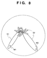
- the signals sent from the antenna elements are combined and, as a result, a signal beam of a radio signal is formed in a prescribed direction, as illustrated in Fig. 7. Since a signal S1 is thus capable of being transmitted almost solely in the direction of a mobile station M1 it is possible to prevent the transmitted signal S1 from acting upon a mobile station M2 as interference.
- the number of array elements in an adaptive array antenna is decided depending upon the extent to which a signal beam is to be concentrated on a specific user, the extent to which signals are to be isolated and the degree to which mutual interference between users is to be reduced.
- An adaptive array antenna of this kind is disclosed in detail in IEEE ASSP Magazine, pp. 4 - 24, April 1988; Barry D. van Veen and Keven Buckley: "Beamforming: A versatile approach to spatial filtering".
- a multicast function is a function for transmitting the same information from a base station to a plurality of mobile stations simultaneously.
- a specific example of a service that relies upon the multicast function is the simultaneous transmission of information (referred to as "multicast data" below) such as traffic information, weather information and stock-market information to a plurality of contract users.
- the multicast data is transmitted upon forming the signal beams S1, S2 individually for the mobile stations M1, M2 of the contracting parties. This is inefficient in terms of multicasting. Further, the multicast data is transmitted separately to the mobile stations M1, M2. This also is inefficient in terms of transmission power. Thus, inefficiencies remain in regard to the transmission of multicast data and there seems to be room for improvement.
- Dybdal et al. (U.S. Patent No.5,781,845) discloses an adaptive transmitting antenna capable of reducing multipath components included in the transmitted signal.
- RALEIGH at al. discloses beamforming technique that enhances remote user received signal quality by using adaptive antenna without the need for feedback from the mobile user.
- an object of the present invention is to provide a wireless telecommunications system and method in which desired information can be transmitted efficiently to a plurality of mobile stations.
- the foregoing object is attained by providing a wireless telecommunications system, base station and method according to claims 1, 6 and 10.
- Fig. 1 illustrates a CDMA mobile radiotelephone system 1 to which the present invention has been applied.
- the mobile radiotelephone system 1 includes a mobile services switching center (MSC) 2, a radio network controller (RNC) 3 and a plurality of base stations 4A to 4C.
- the mobile services switching center 2 which is connected to the radio network controller 3 via a prescribed transmission line, performs call control and registration management, etc., of mobile stations 5A to 5C via the radio network controller 3, and exercises overall control of the system.
- the mobile services switching center 2 is connected to a public switched telephone network (PSTN) 6 via a prescribed transmission line to relay calls between telephones connected to the PSTN 6 and desired ones of the mobile stations 5A to 5C.
- PSTN public switched telephone network
- the radio network controller 3 which is a device for controlling a radio network, connects and disconnects the base stations 4A to 4C and mobile stations 5A to 5C, hands over the mobile stations, controls transmission power, etc.
- the base stations 4A to 4C are transceivers which, on the basis of control performed by the radio network controller 3, actually establish CDMA radio links with the mobile stations 5A to 5C. This enables the base stations 4A to 4C to communicate with other mobile stations in the system, or with other telephones connected to the PSTN 6, via the base stations 4A to 4C.
- the mobile stations 5A to 5C may be portable telephones whose basic function is the voice function or transportable general-purpose computers, for example, each having a radio interface for interfacing the mobile stations 4A to 4C.
- the mobile radiotelephone system 1 has a multicast function in addition to the voice function mentioned above. More specifically, the mobile services switching center 2 is so adapted as to periodically acquire information such as traffic information, weather information and stock-market information from prescribed information sources via the PSTN 6, send this information as multicast data to the base stations 4A to 4C via the radio network controller 3, and send the information to the desired mobile stations 5A to 5C via the base stations 4A to 4C. In such case the multicast data is not sent to all mobile stations but only to mobile stations that have entered into an information-service agreement with a provider of the mobile radiotelephone system 1.
- Information as to whether an agreement has been made is stored, in association with the identification number of the mobile station, in the mobile services switching center 2 of the mobile radiotelephone system 1. This makes it possible to send multicast data only to contract users based upon the stored data.
- the mobile services switching center 2 sends multicast data, which has been acquired periodically via the PSTN 6, to the base stations 4A to 4C via the radio network controller 3.
- a user wishing to receive multicast data inputs a data receive command to the mobile station 5A (or 5B or 5C) by performing a prescribed operation.
- the mobile station 5A (or 5B or 5C) Upon receiving the command, the mobile station 5A (or 5B or 5C) transmits a request command for requesting the multicast data.
- the request command includes mobile station ID information and the type of content desired to be received.
- the request command is received by the base station 4A (or 4B or 4C), whence the command is sent to the mobile services switching center 2 via the radio network controller 3.
- the mobile services switching center 2 Upon receiving the request command, the mobile services switching center 2 determines, based upon the mobile station ID information, whether the mobile station 5A (or 5B or 5C) that sent the request command is that of a contract user. If the mobile station is a contract user, the mobile services switching center 2 instructs the base station 4A (or 4B or 4C) that received the request command to transmit the multicast data to the mobile station 5A (or 5B or 5C).
- the base stations 4A - 4C each have an adaptive array antenna.
- the base station 4A (or 4B or 4C) that was instructed to transmit the multicast data uses it adaptive array antenna to form a signal beam that will point only toward the mobile station 5A (or 5B or 5C) desiring the multicast data and transmits the multicast data solely to this mobile station 5A (or 5B or 5C).
- a single cell may contain one or a plurality of mobile stations desiring multicast data.
- a signal beam that will encompass these plurality of mobile stations simultaneously is formed by the adaptive array antenna to transmit the multicast data to these mobile station at a stroke.
- the base station 4A (or 4B or 4C) is adapted to transmit the multicast data repeatedly a prescribed number of times in order that the multicast data can be received with certainty at the mobile station 5A (or 5B or 5C).
- the multicast data is transmitted to the mobile station.
- a method of transmitting multicast data continuously is conceivable as an approach that contrasts with that of this invention, this would mean transmitting multicast data even when mobile stations desiring such reception are not present within a cell.
- the signal would act as interference and might have a deleterious effect upon mobile stations participating in ordinary individual communication or mobile stations other than those of contracting parties.
- the present invention is adapted to transmit multicast data only when there is a request to receive this data.
- the construction of the base stations 4A to 4C which transmit a signal beam of multicast data in a prescribed direction will now be described. Since the base stations 4A to 4C basically are identical in construction, only the base station 4A will be described.
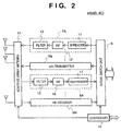
- Fig. 2 shows the construction of the base station 4A. It should be noted, however, that a baseband signal processing circuit and an interface circuit for interfacing the radio network controller 3 are not described here.
- the base station 4A has a plurality of transmitters 7A to 7N and a plurality of receivers 8A to 8N and is adapted so as to be capable of communicating with a plurality of mobile stations simultaneously using these transmitters 7A to 7N and receivers 8A to 8N.
- Individual transmission data such as voice data sent from the radio network controller 3 is input to a signal switch unit 9 via an interface circuit (not shown).
- the signal switch unit 9 comprises a demultiplexer circuit, for example, for assigning input individual transmission data to corresponding ones of the transmitters 7A to 7N.
- the signal switch unit 9 sends individual transmission data to the corresponding transmitters 7A to 7N in the following manner: individual transmission data transmitted on the first communication channel is sent to the first transmitter 7A, individual transmission data transmitted on the second communication channel is sent to the second transmitter 7B, and so on.
- Control data sent from the radio network controller 3 enters a controller 10 via an interface circuit, which is not shown.
- the controller 10 receives the control data from the radio network controller 3, controls the operation of the signal switch unit 9 based upon the control data and controls the operation of an adaptive array antenna 14, which is described later.
- the 1st through nth transmitters 7A - 7N are identically constructed.
- the first transmitter 7A has a spreading circuit 11 to which the entered individual transmission data is input first.
- the spreading circuit 11 multiplies the individual transmission data by a predetermined spreading code that has been allocated to the first communication channel, thereby subjecting the individual transmission data to spread-spectrum modulation.
- CDMA communication communication channels are distinguished from one another by allocating a different spreading code for each channel.
- received data is multiplied by a spreading code the same as that on the transmitting side and despread processing is then executed to restore the data.
- the transmission signal output by the spreading circuit 11 enters a radio-frequency unit (RF) 12.
- RF radio-frequency unit
- the transmission signal output by the radio-frequency unit 12 enters a filter 13, which eliminates unwanted signal components from the signal and then inputs the resulting signal to the adaptive array antenna 14.
- the 2nd through nth transmitters 7B - 7N also multiply input individual transmission data by respective spreading codes assigned thereto, apply spread-spectrum modulation, then subject the transmission signals to frequency conversion processing and filtering processing and output the resulting signals to the adaptive array antenna 14.
- the adaptive array antenna 14 which has a plurality of antenna elements, controls the amplitude and phase of each of the transmission signals applied to respective ones of the plurality of antenna elements to thereby form signal beams in prescribed directions and transmit each signal. More specifically, the adaptive array antenna 14 controls the amplitude and phase of the transmission signal output by the first transmitter 7A, thereby forming and transmitting a signal beam in the direction of the mobile station that is to receive this transmission signal. Similarly, the adaptive array antenna 14 controls the amplitudes and phases of the transmission signals output by the 2nd to nth transmitters 7B to 7N, thereby forming and transmitting signal beams in the direction of the respective mobile stations that are to receive these transmission signals.
- the mobile radiotelephone system 1 forms signal beams S1 and S2 pointing toward the mobile stations M1 and M2, as shown in Fig. 8, at the time of individual transmission, and transmits the individual transmission data to the respective mobile stations M1 and M2. Accordingly, the mobile radiotelephone system 1 makes it possible to reduce interference within the system when an individual data transmission is made to each mobile station.
- signals received from the mobile stations by the adaptive array antenna 14 enter the corresponding 1st through nth receivers 8A - 8N.
- the 1st through nth receivers 8A - 8N are identically constructed.
- Each has a filter 15 which eliminates unwanted components from the received signal, a radio-frequency (RF) unit 16 which subsequently extracts the signal component of the baseband, and a despreading circuit 17 for extracting the received data by executing despread processing using a despreading code identical with that on the transmitting side.
- RF radio-frequency
- multicast data sent from the radio network controller 3 enters the signal switch unit 9 via an interface circuit, which is not shown, in a manner similar to the foregoing.
- the signal switch unit 9 supplies the multicast data solely to, e.g., the transmitter 7A.
- the transmitter 7A applies spread-spectrum modulation to the multicast data, then executes frequency conversion processing to generate a transmission signal and outputs this signal to the adaptive array antenna 14.
- the adaptive array antenna 14 based upon control by the controller 10, adjusts the amplitude and phase of the multicast data transmission signal and supplies the resulting signal to each antenna element, thereby forming a signal beam directed toward this mobile station and transmitting the multicast data transmission signal using this signal beam.
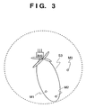
- the adaptive array antenna 14, based upon control by the controller 10, adjusts the amplitude and phase of the multicast data transmission signal and supplies the resulting signal to each antenna element, thereby forming a signal beam S3 that simultaneously covers the plurality of mobile stations M1, M2 desiring to receive the multicast data, as depicted in Fig. 3, and transmitting the multicast data.
- the mobile radiotelephone system 1 transmits the signal to the plurality of mobile stations M1, M2 at one time. This makes it possible to reduce the power of transmission within the cell and, as a result, to reduce interference that acts upon the other mobile station M3 present in the cell.
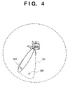
- a signal beam S4 that covers the mobile station M2 that subsequently requested the multicast data is formed by the adaptive array antenna 14, whereby the aforesaid multicast data is sent simultaneously to all mobile stations M1, M2 desiring the multicast data.
- the adaptive array antenna 14 will be described in detail with reference to Fig. 5.
- the adaptive array antenna 14 has a plurality of signal processing units 20A to 20N conforming to the number of communication channels. These signal processing units 20A to 20N process the signals of the respective communication channels.
- signals received by a plurality of antenna elements 21A to 21M enter the signal processing units 20A to 20N via antenna couplers 22A to 22M, respectively.
- Each of the signal processing units 20A to 20N includes multipliers 23A to 23M to which respective ones of the received signals are input, a coefficient calculation unit 24 which supplies coefficients ( ⁇ ' 1 , ⁇ ' 1 ) to ( ⁇ ' M , ⁇ ' M ) by which the received signals are multiplied, and a vector adder 25 for adding the products obtained from the multipliers.
- the coefficients ⁇ ' 1 to ⁇ ' M are for adjusting the amplitudes of the respective received signals, and the coefficients ⁇ ' 1 to ⁇ ' M are for adjusting the phases of the respective received signals.
- the coefficient calculation unit 24 accepts the combined received signal output by the vector adder 25 and performs control so as to maximize the combined received signal by adjusting the coefficients ( ⁇ ' 1 , ⁇ ' 1 ) to ( ⁇ ' M , ⁇ ' M ) while monitoring the combined received signal. Maximization of the combined received signal indicates that the directivity pattern of the antenna is directed toward the mobile station that is the object of reception. Combined received signals thus maximized by such control in the 1st through nth signal processing units 20A to 20N are output to the corresponding 1st through nth receivers 8A - 8N, respectively.
- transmission signals that have been output by the 1st through nth transmitters 7A to 7N are output to the corresponding 1st through nth signal processing units 20A to 20N.
- Each of the signal processing units 20A to 20N includes multipliers 26A to 26M to which respective ones of the transmission signals are input.
- the coefficient calculation unit 24 supplies coefficients ( ⁇ 1 , ⁇ 1 ) to ( ⁇ M , ⁇ M ) by which the transmission signals are multiplied, after which the products obtained from the multipliers are supplied to adders 27A to 27M, respectively, the outputs of which are supplied to the antennas 21A to 21M via the antenna couplers 22A to 22M, respectively.
- the coefficients ⁇ 1 to ⁇ M similarly are for adjusting the amplitudes of the respective transmission signals, and the coefficients ⁇ 1 to ⁇ M are for adjusting the phases of the respective transmission signals.
- the coefficients ( ⁇ ' 1 , ⁇ ' 1 ) to ( ⁇ ' M , ⁇ ' M ) calculated at the time of reception may be used as is as the coefficients ( ⁇ 1 , ⁇ 1 ) to ( ⁇ M , ⁇ M ), it is preferred that the coefficients ( ⁇ 1 , ⁇ 1 ) to ( ⁇ M , ⁇ M ) be obtained by correcting the coefficients ( ⁇ ' 1 , ⁇ ' 1 ) to ( ⁇ ' M , ⁇ ' M ) calculated at the time of reception.
- the transmitting frequency and receiving frequency differ, there is the possibility that the characteristics will differ slightly.
- the directivity pattern of the antenna will be directed toward the mobile station that is the object of transmission if the coefficients ( ⁇ 1 , ⁇ 1 ) to ( ⁇ M , ⁇ M ) based upon the coefficients ⁇ ' 1 , ⁇ ' 1 ) to ( ⁇ ' M , ⁇ ' M ) are used.
- the signal processing units 20A to 20N receive multicast data request commands from each of the mobile stations and first calculate, for every mobile station, coefficients ( ⁇ ' 1 , ⁇ ' 1 ) to ( ⁇ ' M , ⁇ ' M ) for reception purposes based upon the received signals. Once the coefficients ( ⁇ ' 1 , ⁇ ' 1 ) to ( ⁇ ' M , ⁇ ' M ) of every mobile station have been reported to the controller 10, the coefficients are communicated via the controller 10 to the signal processing unit that will take charge of transmission of the multicast data. Assume here that the signal processing unit 20A corresponds to this signal processing unit.
- the coefficient calculation unit 24 of the signal processing unit 20A calculates coefficients ( ⁇ 1 , ⁇ 1 ) to ( ⁇ M , ⁇ M ), which are for transmission purposes, in such a manner that a plurality of mobile stations desiring multicast data will be encompassed simultaneously by a single signal beam.
- the coefficients ( ⁇ 1 , ⁇ 1 ) to ( ⁇ M , ⁇ M ) are supplied to the multipliers 26A to 26M, which proceed to multiply the multicast data transmission signals by these coefficients.
- the transmission signals thus adjusted in phase and amplitude owing to multiplication by the coefficients ( ⁇ 1 , ⁇ 1 ) to ( ⁇ M , ⁇ M ) are supplied to the antenna elements 21A to 21M via the adders 27A to 27M and antenna couplers 22A to 22M, respectively, whereupon the transmission signals are combined to form a signal beam that encompasses the plurality of mobile stations M1, M2 simultaneously, as shown in Figs. 6A to 6C.
- multicast data can be transmitted simultaneously to the plurality of mobile stations M1, M2 desiring the multicast data.
- the adaptive array antenna 14 calculates coefficients ( ⁇ 1 , ⁇ 1 ) to ( ⁇ M , ⁇ M ) that will point the signal beam solely toward the mobile station of the communicating party and sends a signal solely to this mobile station of the communicating party.
- the adaptive array antenna 14 calculates coefficients ( ⁇ 1 , ⁇ 1 ) to ( ⁇ M , ⁇ M ) that will cause a plurality of mobile stations requesting multicast data to be covered by one signal beam and sends the multicast data to these plurality of mobile stations simultaneously.
- the mobile radiotelephone system 1 calculates the coefficients ( ⁇ 1 , ⁇ 1 ) to ( ⁇ M , ⁇ M ) based upon received signals prevailing when multicast data request commands are received, multiplies the transmission signals by these coefficients ( ⁇ 1 , ⁇ 1 ) to ( ⁇ M , ⁇ M ) and transmits the respective signals obtained as a result to the plurality of antennas 21A to 21M.
- the transmission signals thus adjusted in amplitude and phase are output to the plurality of antennas 21A to 21M, the transmission signals are combined and a signal beam pointing in a prescribed direction is formed.
- the system calculates the coefficients ( ⁇ 1 , ⁇ 1 ) to ( ⁇ M , ⁇ M ) that will cause the plurality of mobile stations requesting multicast data to be covered by one signal beam. Consequently, the signal beam of the multicast data output by the adaptive array antenna 14 covers a plurality of base stations desiring the multicast data, as illustrated in Fig. 3, and the multicast data can be transmitted simultaneously to the plurality of mobile stations efficiently as a result. Furthermore, since the multicast data is capable of being transmitted to the plurality of mobile stations at one time, transmission power is reduced compared with the transmission power needed when transmitting multicast data individually. The result is a reduction in interfering waves within the cell. Moreover, since interference within the cell can be reduced, it is possible to increase system capacity.
- transmission of multicast data is carried out by forming a signal beam that will simultaneously encompass a plurality of mobile stations desiring the multicast data and sending the multicast data over this beam.
- multicast data can be transmitted to a plurality of mobile stations at the same time, the multicast data can be transmitted efficiently and interference within the cell can be reduced.
- the above-described embodiment relates to a case where multicast data is acquired via the PSTN 6.
- the present invention is not limited to this arrangement.
- the mobile services switching center 2 may be provided with input means and the multicast data may be entered via this input means.
- the above-described embodiment relates to a case where the coefficients ( ⁇ 1 , ⁇ 1 ) to ( ⁇ M , ⁇ M ) are calculated based upon a received signal that prevailed when a multicast data request command was received.
- the present invention is not limited to such an arrangement, for it is permissible to calculate the coefficients ( ⁇ 1 , ⁇ 1 ) to ( ⁇ M , ⁇ M ) based upon another received signal sent from a mobile station, such as a received signal prevailing at the time of individual communication.
- Still another feasible arrangement is to provide a mobile station with a receiving device used in a GPS system, communicate mobile-station position information, which has been computed by this receiving device, to the base station, calculate coefficients based upon this position information representing the mobile station, and form a signal beam that will cover a plurality of mobile stations.
- the above-described embodiment relates to a case where the present invention is applied to a communication system with a CDMA communications scheme.
- the present invention is not limited to such application but can be adapted so as to be applicable to any wireless communications systems such as a TDMA and FDMA system.
- the above-described embodiment relates to a case where the present invention is applied to the mobile radiotelephone system 1.
- the present invention is not limited to such application but can be adapted so as to be applicable to a wireless LAN system or other wireless system.
- What is essential is that in a case where identical information is transmitted to a plurality of mobile stations in a wireless communications system, in which radio links are established between a base station and a plurality of mobile stations by predetermined wireless communication technique, and of which base station communicates by forming a signal beam substantially in the direction to certain one mobile station to which a base station communicates with, effects similar to those realized in such case will be obtained if a signal beam that covers the plurality of mobile stations simultaneously is formed and the information is transmitted by means of this signal beam.
- the present invention is advantageous in that information can be sent to plurality of mobile stations simultaneously by so arranging it that the information is transmitted to the plurality of base stations by forming such a signal beam that will cover the plurality of base stations simultaneously. This makes it possible to send information in a highly efficient. In addition, because transmission power can be reduced, interference acting upon other mobile stations can be suppressed.
Abstract
Description
- This invention relates to a wireless telecommunications system in which it is possible to transmit desired information to a plurality of mobile stations in an efficient manner.
- Great strides in wireless telecommunications techniques have been made in recent years and this has been accompanied by the implementation and practical use of various wireless communications systems. A mobile radiotelephone system or so-called cellular phone system best typifies such wireless telecommunications systems.
- Various wireless telecommunications schemes have been proposed for such mobile radiotelephone systems. For example, FDMA (Frequency Division Multiple Access) is currently being employed in analog mobile radiotelephone systems. According to the FDMA scheme, a single communication channel is allocated to a single radio frequency and communication channels used by respective ones of a plurality of users are set to different radio frequencies on a per-user basis.
- TDMA (Time-Division Multiple Access) is currently being employed in digital mobile radiotelephone systems, which have rapidly come into widespread use in recent years. With TDMA, a single radio frequency is divided up into a plurality of time slots and signals are transmitted at the timings of time slots that have been allocated to the local station, whereby three or six communication channels, for example, are formed on one radio frequency. In accordance with this scheme, a plurality of communication channels can be formed on a single radio frequency, as a result of which the capacity of the system can be enlarged over that of the analog scheme.
- CDMA (Code-Division Multiple Access) has recently been proposed as a communications scheme for the next-generation of mobile radiotelephone systems. With CDMA, the same radio frequency band is shared simultaneously by a plurality of users. At the time of transmission, transmitted data is multiplied by spreading codes that differ for each user, thereby forming a plurality of channels on the same frequency. Since this scheme makes it possible for the same frequency band to be used by all cells of a cellular system, the system capacity can be increased further over that of the TDMA scheme. For this reason, CDMA is currently the focus of interest in regard to its application to the next-generation of mobile communications.
- Since a mobile radiotelephone systems using CDMA is such that common use is made of the same frequency, a situation arises in which a signal transmitted by a certain user acts upon another user as interference. This is an important problem encountered when constructing the communications system. Accordingly, a variety of expedients for reducing interference waves in CDMA communications system have been devised. One is the usage of an adaptive array antenna. An adaptive array antenna increases system capacity by reducing interference waves inflicted upon other users.
- An adaptive array antenna is composed of a plurality of antenna elements. When the amplitudes and phases of signals to be transmitted are adjusted and the signals are then supplied to respective ones of the antenna elements, the signals sent from the antenna elements are combined and, as a result, a signal beam of a radio signal is formed in a prescribed direction, as illustrated in Fig. 7. Since a signal S1 is thus capable of being transmitted almost solely in the direction of a mobile station M1 it is possible to prevent the transmitted signal S1 from acting upon a mobile station M2 as interference.
- The number of array elements in an adaptive array antenna is decided depending upon the extent to which a signal beam is to be concentrated on a specific user, the extent to which signals are to be isolated and the degree to which mutual interference between users is to be reduced. An adaptive array antenna of this kind is disclosed in detail in IEEE ASSP Magazine, pp. 4 - 24, April 1988; Barry D. van Veen and Keven Buckley: "Beamforming: A versatile approach to spatial filtering".
- There is demand for various functions other than a voice function, and particularly intense demand for a multicast function, in next-generation mobile radiotelephone systems. A multicast function is a function for transmitting the same information from a base station to a plurality of mobile stations simultaneously. A specific example of a service that relies upon the multicast function is the simultaneous transmission of information (referred to as "multicast data" below) such as traffic information, weather information and stock-market information to a plurality of contract users.
- If an attempt is made to implement such a multicast function using a CDMA mobile radiotelephone system, a conceivable approach is to form signal beams S1 and S2 individually in the directions of contract mobile stations M1 and M2 using an adaptive array antenna in a manner similar to that of ordinary individual communication, and transmit the multicast data individually by these signal beams S1, S2, as shown in Fig. 8.
- With this method, however, the multicast data is transmitted upon forming the signal beams S1, S2 individually for the mobile stations M1, M2 of the contracting parties. This is inefficient in terms of multicasting. Further, the multicast data is transmitted separately to the mobile stations M1, M2. This also is inefficient in terms of transmission power. Thus, inefficiencies remain in regard to the transmission of multicast data and there seems to be room for improvement.
- Forssén et al. (U.S. Patent No. 5,615,409) discloses a base station for transmitting and receiving data by using 2 classes of channels each of which has different antenna lobe from each other. These lobes are formed by adaptive antenna array.
- Forssén et al. (U.S. Patent No. 5,649,287) discloses technique for forming a wide antenna lobe without any deep nulls by a plurality of antenna arrays each of which having a narrow antenna lobe.
- Dybdal et al. (U.S. Patent No.5,781,845) discloses an adaptive transmitting antenna capable of reducing multipath components included in the transmitted signal.
- RALEIGH at al. (WO 97/00543) discloses beamforming technique that enhances remote user received signal quality by using adaptive antenna without the need for feedback from the mobile user.
- Accordingly, an object of the present invention is to provide a wireless telecommunications system and method in which desired information can be transmitted efficiently to a plurality of mobile stations.
- According to the present invention, the foregoing object is attained by providing a wireless telecommunications system, base station and method according to
claims - Other features and advantages of the present invention will be apparent from the following description taken in conjunction with the accompanying drawings, in which like reference characters designate the same or similar parts throughout the figures thereof.
-
- Fig. 1 is a block diagram showing the configuration of a CDMA mobile radiotelephone system to which the present invention has been applied;
- Fig. 2 is a block diagram showing the construction of a base station according to the present invention;
- Fig. 3 is a beam waveform diagram useful in describing a signal beam that covers a plurality of mobile stations;
- Fig. 4 is a beam waveform diagram useful in describing an instance where a mobile station wishing to receive multicast data appears at a later time;
- Fig. 5 is a block diagram showing the construction of an adaptive array antenna;
- Figs. 6A to 6C is a schematic diagram showing the principle in accordance with which a signal beam is formed in a prescribed direction by the adaptive array antenna;
- Fig. 7 is a beam waveform diagram useful in describing an adaptive array antenna; and
- Fig. 8 is a beam waveform diagram useful in describing an instance where multicast data is transmitted individually using the adaptive array antenna.
- Fig. 1 illustrates a CDMA
mobile radiotelephone system 1 to which the present invention has been applied. Themobile radiotelephone system 1 includes a mobile services switching center (MSC) 2, a radio network controller (RNC) 3 and a plurality ofbase stations 4A to 4C. The mobileservices switching center 2, which is connected to theradio network controller 3 via a prescribed transmission line, performs call control and registration management, etc., ofmobile stations 5A to 5C via theradio network controller 3, and exercises overall control of the system. Further, the mobileservices switching center 2 is connected to a public switched telephone network (PSTN) 6 via a prescribed transmission line to relay calls between telephones connected to thePSTN 6 and desired ones of themobile stations 5A to 5C. - The
radio network controller 3, which is a device for controlling a radio network, connects and disconnects thebase stations 4A to 4C andmobile stations 5A to 5C, hands over the mobile stations, controls transmission power, etc. - The
base stations 4A to 4C are transceivers which, on the basis of control performed by theradio network controller 3, actually establish CDMA radio links with themobile stations 5A to 5C. This enables thebase stations 4A to 4C to communicate with other mobile stations in the system, or with other telephones connected to the PSTN 6, via thebase stations 4A to 4C. - Though the three
base stations 4A to 4C and threemobile stations 5A to 5C are discussed here for the sake of simplicity, the numbers of these stations are not limited to those of this embodiment. Further, themobile stations 5A to 5C may be portable telephones whose basic function is the voice function or transportable general-purpose computers, for example, each having a radio interface for interfacing themobile stations 4A to 4C. - The
mobile radiotelephone system 1 has a multicast function in addition to the voice function mentioned above. More specifically, the mobileservices switching center 2 is so adapted as to periodically acquire information such as traffic information, weather information and stock-market information from prescribed information sources via thePSTN 6, send this information as multicast data to thebase stations 4A to 4C via theradio network controller 3, and send the information to the desiredmobile stations 5A to 5C via thebase stations 4A to 4C. In such case the multicast data is not sent to all mobile stations but only to mobile stations that have entered into an information-service agreement with a provider of themobile radiotelephone system 1. - Information as to whether an agreement has been made is stored, in association with the identification number of the mobile station, in the mobile
services switching center 2 of themobile radiotelephone system 1. This makes it possible to send multicast data only to contract users based upon the stored data. - The multicast function will now be described in greater detail.
- The mobile
services switching center 2 sends multicast data, which has been acquired periodically via thePSTN 6, to thebase stations 4A to 4C via theradio network controller 3. - A user wishing to receive multicast data inputs a data receive command to the
mobile station 5A (or 5B or 5C) by performing a prescribed operation. Upon receiving the command, themobile station 5A (or 5B or 5C) transmits a request command for requesting the multicast data. For example, the request command includes mobile station ID information and the type of content desired to be received. The request command is received by thebase station 4A (or 4B or 4C), whence the command is sent to the mobileservices switching center 2 via theradio network controller 3. - Upon receiving the request command, the mobile
services switching center 2 determines, based upon the mobile station ID information, whether themobile station 5A (or 5B or 5C) that sent the request command is that of a contract user. If the mobile station is a contract user, the mobileservices switching center 2 instructs thebase station 4A (or 4B or 4C) that received the request command to transmit the multicast data to themobile station 5A (or 5B or 5C). Thebase stations 4A - 4C each have an adaptive array antenna. Thebase station 4A (or 4B or 4C) that was instructed to transmit the multicast data uses it adaptive array antenna to form a signal beam that will point only toward themobile station 5A (or 5B or 5C) desiring the multicast data and transmits the multicast data solely to thismobile station 5A (or 5B or 5C). - It should be noted that a single cell may contain one or a plurality of mobile stations desiring multicast data. In a case where a plurality of mobile stations desiring multicast data reside in one cell, a signal beam that will encompass these plurality of mobile stations simultaneously is formed by the adaptive array antenna to transmit the multicast data to these mobile station at a stroke. Further, the
base station 4A (or 4B or 4C) is adapted to transmit the multicast data repeatedly a prescribed number of times in order that the multicast data can be received with certainty at themobile station 5A (or 5B or 5C). - When a request to receive multicast data is thus generated in the
mobile radiotelephone system 1 of the present invention, the multicast data is transmitted to the mobile station. Though a method of transmitting multicast data continuously is conceivable as an approach that contrasts with that of this invention, this would mean transmitting multicast data even when mobile stations desiring such reception are not present within a cell. As a consequence, the signal would act as interference and might have a deleterious effect upon mobile stations participating in ordinary individual communication or mobile stations other than those of contracting parties. In order to avoid this, therefore, the present invention is adapted to transmit multicast data only when there is a request to receive this data. - The construction of the
base stations 4A to 4C which transmit a signal beam of multicast data in a prescribed direction will now be described. Since thebase stations 4A to 4C basically are identical in construction, only thebase station 4A will be described. - Fig. 2 shows the construction of the
base station 4A. It should be noted, however, that a baseband signal processing circuit and an interface circuit for interfacing theradio network controller 3 are not described here. - As shown in Fig. 2, the
base station 4A has a plurality oftransmitters 7A to 7N and a plurality ofreceivers 8A to 8N and is adapted so as to be capable of communicating with a plurality of mobile stations simultaneously using thesetransmitters 7A to 7N andreceivers 8A to 8N. Individual transmission data such as voice data sent from theradio network controller 3 is input to asignal switch unit 9 via an interface circuit (not shown). - The
signal switch unit 9 comprises a demultiplexer circuit, for example, for assigning input individual transmission data to corresponding ones of thetransmitters 7A to 7N. On the assumption that the 1st throughnth transmitters 7A to 7N correspond to 1st through nth communication channels, respectively, thesignal switch unit 9 sends individual transmission data to the correspondingtransmitters 7A to 7N in the following manner: individual transmission data transmitted on the first communication channel is sent to thefirst transmitter 7A, individual transmission data transmitted on the second communication channel is sent to the second transmitter 7B, and so on. - Control data sent from the
radio network controller 3 enters acontroller 10 via an interface circuit, which is not shown. Thecontroller 10 receives the control data from theradio network controller 3, controls the operation of thesignal switch unit 9 based upon the control data and controls the operation of anadaptive array antenna 14, which is described later. - The 1st through
nth transmitters 7A - 7N are identically constructed. Thefirst transmitter 7A has a spreadingcircuit 11 to which the entered individual transmission data is input first. The spreadingcircuit 11 multiplies the individual transmission data by a predetermined spreading code that has been allocated to the first communication channel, thereby subjecting the individual transmission data to spread-spectrum modulation. - In CDMA communication, communication channels are distinguished from one another by allocating a different spreading code for each channel. On the receiving side, received data is multiplied by a spreading code the same as that on the transmitting side and despread processing is then executed to restore the data.
- The transmission signal output by the spreading
circuit 11 enters a radio-frequency unit (RF) 12. Here the signal undergoes frequency conversion processing so as to be converted to a transmission signal of a prescribed frequency band. The transmission signal output by the radio-frequency unit 12 enters afilter 13, which eliminates unwanted signal components from the signal and then inputs the resulting signal to theadaptive array antenna 14. - Similarly, the 2nd through nth transmitters 7B - 7N also multiply input individual transmission data by respective spreading codes assigned thereto, apply spread-spectrum modulation, then subject the transmission signals to frequency conversion processing and filtering processing and output the resulting signals to the
adaptive array antenna 14. - On the basis of control by the
controller 10, theadaptive array antenna 14, which has a plurality of antenna elements, controls the amplitude and phase of each of the transmission signals applied to respective ones of the plurality of antenna elements to thereby form signal beams in prescribed directions and transmit each signal. More specifically, theadaptive array antenna 14 controls the amplitude and phase of the transmission signal output by thefirst transmitter 7A, thereby forming and transmitting a signal beam in the direction of the mobile station that is to receive this transmission signal. Similarly, theadaptive array antenna 14 controls the amplitudes and phases of the transmission signals output by the 2nd to nth transmitters 7B to 7N, thereby forming and transmitting signal beams in the direction of the respective mobile stations that are to receive these transmission signals. - As a result of the operation described above, the
mobile radiotelephone system 1 forms signal beams S1 and S2 pointing toward the mobile stations M1 and M2, as shown in Fig. 8, at the time of individual transmission, and transmits the individual transmission data to the respective mobile stations M1 and M2. Accordingly, themobile radiotelephone system 1 makes it possible to reduce interference within the system when an individual data transmission is made to each mobile station. - Meanwhile, signals received from the mobile stations by the
adaptive array antenna 14 enter the corresponding 1st throughnth receivers 8A - 8N. The 1st throughnth receivers 8A - 8N are identically constructed. Each has afilter 15 which eliminates unwanted components from the received signal, a radio-frequency (RF)unit 16 which subsequently extracts the signal component of the baseband, and adespreading circuit 17 for extracting the received data by executing despread processing using a despreading code identical with that on the transmitting side. Each item of received data thus extracted is sent to theradio network controller 3 via thesignal switch unit 9 and is then sent to the terminal of the communicating party. - Operation in the case of a multicast data transmission, which differs from the individual data transmission set forth above, will now be described.
- Specifically, multicast data sent from the
radio network controller 3 enters thesignal switch unit 9 via an interface circuit, which is not shown, in a manner similar to the foregoing. On the basis of control exercised by thecontroller 10, thesignal switch unit 9 supplies the multicast data solely to, e.g., thetransmitter 7A. In a manner similar to that when an individual transmission is made, thetransmitter 7A applies spread-spectrum modulation to the multicast data, then executes frequency conversion processing to generate a transmission signal and outputs this signal to theadaptive array antenna 14. - In a case where only one mobile station that is to receive the multicast data resides in a cell, the
adaptive array antenna 14, based upon control by thecontroller 10, adjusts the amplitude and phase of the multicast data transmission signal and supplies the resulting signal to each antenna element, thereby forming a signal beam directed toward this mobile station and transmitting the multicast data transmission signal using this signal beam. - In a case where a plurality of mobile stations that wish to receive the multicast data reside in a cell, the
adaptive array antenna 14, based upon control by thecontroller 10, adjusts the amplitude and phase of the multicast data transmission signal and supplies the resulting signal to each antenna element, thereby forming a signal beam S3 that simultaneously covers the plurality of mobile stations M1, M2 desiring to receive the multicast data, as depicted in Fig. 3, and transmitting the multicast data. Thus, when multicast data is transmitted to the plurality of mobile stations M1, M2, themobile radiotelephone system 1 transmits the signal to the plurality of mobile stations M1, M2 at one time. This makes it possible to reduce the power of transmission within the cell and, as a result, to reduce interference that acts upon the other mobile station M3 present in the cell. - In an instance where the mobile station M1 receiving the multicast data is already inside the cell and the other mobile station M2 then issues a multicast data request anew, as illustrated in Fig. 4, a signal beam S4 that covers the mobile station M2 that subsequently requested the multicast data is formed by the
adaptive array antenna 14, whereby the aforesaid multicast data is sent simultaneously to all mobile stations M1, M2 desiring the multicast data. - The
adaptive array antenna 14 will be described in detail with reference to Fig. 5. - As shown in Fig. 5, the
adaptive array antenna 14 has a plurality ofsignal processing units 20A to 20N conforming to the number of communication channels. Thesesignal processing units 20A to 20N process the signals of the respective communication channels. - First, at the time of individual communication, signals received by a plurality of
antenna elements 21A to 21M enter thesignal processing units 20A to 20N viaantenna couplers 22A to 22M, respectively. Each of thesignal processing units 20A to 20N includesmultipliers 23A to 23M to which respective ones of the received signals are input, acoefficient calculation unit 24 which supplies coefficients (γ'1, θ'1) to (γ'M, θ'M) by which the received signals are multiplied, and avector adder 25 for adding the products obtained from the multipliers. - Among the coefficients (γ'1,θ'1) to (γ'M,θ'M) output by the
coefficient calculation unit 24, the coefficients γ'1 to γ'M are for adjusting the amplitudes of the respective received signals, and the coefficients θ'1 to θ'M are for adjusting the phases of the respective received signals. - The
coefficient calculation unit 24 accepts the combined received signal output by thevector adder 25 and performs control so as to maximize the combined received signal by adjusting the coefficients (γ'1,θ'1) to (γ'M,θ'M) while monitoring the combined received signal. Maximization of the combined received signal indicates that the directivity pattern of the antenna is directed toward the mobile station that is the object of reception. Combined received signals thus maximized by such control in the 1st through nthsignal processing units 20A to 20N are output to the corresponding 1st throughnth receivers 8A - 8N, respectively. - Meanwhile, transmission signals that have been output by the 1st through
nth transmitters 7A to 7N are output to the corresponding 1st through nthsignal processing units 20A to 20N. Each of thesignal processing units 20A to 20N includesmultipliers 26A to 26M to which respective ones of the transmission signals are input. Thecoefficient calculation unit 24 supplies coefficients (γ1,θ1) to (γM,θM) by which the transmission signals are multiplied, after which the products obtained from the multipliers are supplied toadders 27A to 27M, respectively, the outputs of which are supplied to theantennas 21A to 21M via theantenna couplers 22A to 22M, respectively. - The coefficients γ1 to γM similarly are for adjusting the amplitudes of the respective transmission signals, and the coefficients θ1 to θM are for adjusting the phases of the respective transmission signals. Though the coefficients (γ'1,θ'1) to (γ'M,θ'M) calculated at the time of reception may be used as is as the coefficients (γ1,θ1) to (γM,θM), it is preferred that the coefficients (γ1,θ1) to (γM,θM) be obtained by correcting the coefficients (γ'1,θ'1) to (γ'M,θ'M) calculated at the time of reception. The reason for this is that if the transmitting frequency and receiving frequency differ, there is the possibility that the characteristics will differ slightly. In any case, since the transmitting pattern and the receiving pattern of the antenna generally are considered to be the same, the directivity pattern of the antenna will be directed toward the mobile station that is the object of transmission if the coefficients (γ1,θ1) to (γM,θM) based upon the coefficients γ'1,θ'1) to (γ'M,θ'M) are used.
- When a multicast data transmission is made, on the other hand, the
signal processing units 20A to 20N receive multicast data request commands from each of the mobile stations and first calculate, for every mobile station, coefficients (γ'1,θ'1) to (γ'M,θ'M) for reception purposes based upon the received signals. Once the coefficients (γ'1,θ'1) to (γ'M,θ'M) of every mobile station have been reported to thecontroller 10, the coefficients are communicated via thecontroller 10 to the signal processing unit that will take charge of transmission of the multicast data. Assume here that thesignal processing unit 20A corresponds to this signal processing unit. - On the basis of the coefficients (γ'1,θ'1) to γ'M,θ'M) of every mobile station, the
coefficient calculation unit 24 of thesignal processing unit 20A calculates coefficients (γ1,θ1) to (γM,θM), which are for transmission purposes, in such a manner that a plurality of mobile stations desiring multicast data will be encompassed simultaneously by a single signal beam. The coefficients (γ1,θ1) to (γM,θM) are supplied to themultipliers 26A to 26M, which proceed to multiply the multicast data transmission signals by these coefficients. - The transmission signals thus adjusted in phase and amplitude owing to multiplication by the coefficients (γ1,θ1) to (γM,θM) are supplied to the
antenna elements 21A to 21M via theadders 27A to 27M andantenna couplers 22A to 22M, respectively, whereupon the transmission signals are combined to form a signal beam that encompasses the plurality of mobile stations M1, M2 simultaneously, as shown in Figs. 6A to 6C. As a result, multicast data can be transmitted simultaneously to the plurality of mobile stations M1, M2 desiring the multicast data. - Thus, at the time of individual transmission, the
adaptive array antenna 14 calculates coefficients (γ1,θ1) to (γM,θM) that will point the signal beam solely toward the mobile station of the communicating party and sends a signal solely to this mobile station of the communicating party. At the time of multicast data transmission, on the other hand, theadaptive array antenna 14 calculates coefficients (γ1,θ1) to (γM,θM) that will cause a plurality of mobile stations requesting multicast data to be covered by one signal beam and sends the multicast data to these plurality of mobile stations simultaneously. - The arrangement described above is such that if multicast data is transmitted, the
mobile radiotelephone system 1 calculates the coefficients (γ1,θ1) to (γM,θM) based upon received signals prevailing when multicast data request commands are received, multiplies the transmission signals by these coefficients (γ1,θ1) to (γM,θM) and transmits the respective signals obtained as a result to the plurality ofantennas 21A to 21M. When the transmission signals thus adjusted in amplitude and phase are output to the plurality ofantennas 21A to 21M, the transmission signals are combined and a signal beam pointing in a prescribed direction is formed. - When multicast data is transmitted in the
mobile radiotelephone system 1, the system calculates the coefficients (γ1,θ1) to (γM,θM) that will cause the plurality of mobile stations requesting multicast data to be covered by one signal beam. Consequently, the signal beam of the multicast data output by theadaptive array antenna 14 covers a plurality of base stations desiring the multicast data, as illustrated in Fig. 3, and the multicast data can be transmitted simultaneously to the plurality of mobile stations efficiently as a result. Furthermore, since the multicast data is capable of being transmitted to the plurality of mobile stations at one time, transmission power is reduced compared with the transmission power needed when transmitting multicast data individually. The result is a reduction in interfering waves within the cell. Moreover, since interference within the cell can be reduced, it is possible to increase system capacity. - In accordance with the arrangement set forth above, transmission of multicast data is carried out by forming a signal beam that will simultaneously encompass a plurality of mobile stations desiring the multicast data and sending the multicast data over this beam. As a result, multicast data can be transmitted to a plurality of mobile stations at the same time, the multicast data can be transmitted efficiently and interference within the cell can be reduced.
- The above-described embodiment relates to a case where multicast data is acquired via the
PSTN 6. However, the present invention is not limited to this arrangement. By way of example, the mobileservices switching center 2 may be provided with input means and the multicast data may be entered via this input means. - Further, the above-described embodiment relates to a case where the coefficients (γ1,θ1) to (γM,θM) are calculated based upon a received signal that prevailed when a multicast data request command was received. However, the present invention is not limited to such an arrangement, for it is permissible to calculate the coefficients (γ1,θ1) to (γM,θM) based upon another received signal sent from a mobile station, such as a received signal prevailing at the time of individual communication. Still another feasible arrangement is to provide a mobile station with a receiving device used in a GPS system, communicate mobile-station position information, which has been computed by this receiving device, to the base station, calculate coefficients based upon this position information representing the mobile station, and form a signal beam that will cover a plurality of mobile stations.
- Further, the above-described embodiment relates to a case where the present invention is applied to a communication system with a CDMA communications scheme. However, the present invention is not limited to such application but can be adapted so as to be applicable to any wireless communications systems such as a TDMA and FDMA system.
- Further, the above-described embodiment relates to a case where the present invention is applied to the
mobile radiotelephone system 1. However, the present invention is not limited to such application but can be adapted so as to be applicable to a wireless LAN system or other wireless system. What is essential is that in a case where identical information is transmitted to a plurality of mobile stations in a wireless communications system, in which radio links are established between a base station and a plurality of mobile stations by predetermined wireless communication technique, and of which base station communicates by forming a signal beam substantially in the direction to certain one mobile station to which a base station communicates with, effects similar to those realized in such case will be obtained if a signal beam that covers the plurality of mobile stations simultaneously is formed and the information is transmitted by means of this signal beam. - Further, though an adaptive array antenna is used in the foregoing embodiment, any other means and methods may be used as long as directivity can be controlled.
- The present invention is advantageous in that information can be sent to plurality of mobile stations simultaneously by so arranging it that the information is transmitted to the plurality of base stations by forming such a signal beam that will cover the plurality of base stations simultaneously. This makes it possible to send information in a highly efficient. In addition, because transmission power can be reduced, interference acting upon other mobile stations can be suppressed.
- As many apparently widely different embodiments of the present invention can be made without departing from the scope thereof, it is to be understood that the invention is not limited to the specific embodiments thereof except as defined in the appended claims.
Claims (13)
- A wireless telecommunications system, having at least one base station and mobile station, in which radio links are established between said base station, which is provided with an antenna whose directivity is capable of being controlled, and said mobile station, wherein when communication is performed with one of said mobile stations, a signal beam pointing substantially toward only said one mobile station is formed by said antenna to communicate with said one mobile station;
said base station forming a multicast signal beam, which is directed only toward a plurality of specific mobile stations which are permitted to receive specific information, by said antenna when said specific information is to be sent to the plurality of said specific mobile stations, and sending this information by said multicast signal beam. - The system according to claim 1, wherein said base station transmits said specific information in response to a request from one of said specific mobile stations.
- The system according to claim 1, wherein said antenna is formed from a plurality of antenna elements, and said base station adjusts, by multiplying coefficients, amplitude and phase of a transmission signal generated based upon said specific information to be transmitted and transmits the resulting signals from respective ones of the plurality of said antenna elements, thereby forming the multicast signal beam.
- The system according to claim 3, wherein said base station calculates said coefficients based upon reception signals received from said specific mobile stations.
- The system according to any one of claims 1 to 4, wherein said antenna is an adaptive array antenna.
- A base station for establishing radio links with mobile stations, wherein when communication is performed with one of said mobile stations, a signal beam pointing toward only said one mobile station is formed by an antenna, the directivity whereof is capable of being controlled, to communicate with said one mobile station;
wherein when a specific information is to be sent to a plurality of specific mobile stations which are permitted to receive said specific information, a multicast signal beam directed only toward the plurality of said specific mobile stations is formed by said antenna and said specific information is sent by said multicast signal beam. - The base station according to claim 6, wherein said specific information is transmitted in response to a request from one of said specific mobile stations.
- The base station according to claim 6, wherein said antenna is formed from a plurality of antenna elements, and amplitude and phase of a transmission signal generated based upon said specific information to be transmitted are adjusted by multiplying coefficients and the resulting signals are transmitted from respective ones of the plurality of said antenna elements, thereby forming said multicast signal beam.
- The base station according to claim 8, wherein said base station calculates said coefficients based upon reception signals received from said specific mobile stations.
- A telecommunications method of establishing radio links between a base station, which is provided with an adaptive array antenna, and mobile stations, wherein when communication is performed with one of said mobile stations, a signal beam pointing toward only said one mobile station is formed by said adaptive array antenna to communicate with said mobile station;
said base station forming a multicast signal beam, which covers only a plurality of specific mobile stations which are permitted to receive specific information simultaneously, by said adaptive array antenna when said specific information is to be sent to the plurality of said specific mobile stations, and sending this information by said multicast signal beam. - The method according to claim 10, wherein said base station transmits said specific information in response to a request from one of said specific mobile stations.
- The method according to claim 10, wherein said base station adjusts, by multiplying coefficients, amplitude and phase of a transmission signal generated based upon said specific information to be transmitted and transmits the resulting signals from respective ones of a plurality of antenna elements of said adaptive array antenna, thereby forming said multicast signal beam.
- The method according to claim 12, wherein said base station calculates said coefficients based upon reception signals received from said specific mobile stations.
Applications Claiming Priority (3)
| Application Number | Priority Date | Filing Date | Title |
|---|---|---|---|
| JP7013099 | 1999-03-16 | ||
| JP07013099A JP3987229B2 (en) | 1999-03-16 | 1999-03-16 | Wireless communication system, base station thereof, and communication method thereof |
| PCT/JP2000/001502 WO2000055986A1 (en) | 1999-03-16 | 2000-03-13 | Wireless telecommunication system, base station thereof and beamforming telecommunications method |
Publications (2)
| Publication Number | Publication Date |
|---|---|
| EP1163740A1 EP1163740A1 (en) | 2001-12-19 |
| EP1163740B1 true EP1163740B1 (en) | 2006-05-31 |
Family
ID=13422684
Family Applications (1)
| Application Number | Title | Priority Date | Filing Date |
|---|---|---|---|
| EP00908032A Expired - Lifetime EP1163740B1 (en) | 1999-03-16 | 2000-03-13 | Wireless telecommunications system, base station thereof and beamforming telecommunications method |
Country Status (14)
| Country | Link |
|---|---|
| US (1) | US7805167B1 (en) |
| EP (1) | EP1163740B1 (en) |
| JP (1) | JP3987229B2 (en) |
| KR (1) | KR100635415B1 (en) |
| CN (1) | CN1143455C (en) |
| AR (1) | AR022916A1 (en) |
| AT (1) | ATE328404T1 (en) |
| AU (1) | AU2943500A (en) |
| BR (1) | BR0009028A (en) |
| CA (1) | CA2367998C (en) |
| DE (1) | DE60028355T2 (en) |
| TW (1) | TW490984B (en) |
| WO (1) | WO2000055986A1 (en) |
| ZA (1) | ZA200107556B (en) |
Families Citing this family (35)
| Publication number | Priority date | Publication date | Assignee | Title |
|---|---|---|---|---|
| KR100525390B1 (en) * | 2001-06-05 | 2005-11-02 | 엘지전자 주식회사 | Method of Beam Forming for Common Channel |
| US20030161410A1 (en) | 2002-02-26 | 2003-08-28 | Martin Smith | Radio communications device with adaptive combination |
| US6862456B2 (en) * | 2002-03-01 | 2005-03-01 | Cognio, Inc. | Systems and methods for improving range for multicast wireless communication |
| US6785520B2 (en) | 2002-03-01 | 2004-08-31 | Cognio, Inc. | System and method for antenna diversity using equal power joint maximal ratio combining |
| CN100370705C (en) * | 2004-06-03 | 2008-02-20 | 大唐移动通信设备有限公司 | Method for configuring down channel transmission power of multiaerial system |
| KR100651532B1 (en) * | 2004-08-14 | 2006-11-29 | 삼성전자주식회사 | Method and appratus for a transmission of wireless lan information in a mobile telecommunication network for wireless lan interworking |
| JP4654663B2 (en) * | 2004-11-02 | 2011-03-23 | 日本電気株式会社 | Radio base station, mobile communication system, and broadcast information transfer method |
| JP2006287755A (en) | 2005-04-01 | 2006-10-19 | Ntt Docomo Inc | Receiving apparatus, receiving method, transmitting apparatus and transmitting method for up-link channel |
| JP4732116B2 (en) * | 2005-10-14 | 2011-07-27 | キヤノン株式会社 | Wireless communication method, communication apparatus, and system |
| DE102006005281A1 (en) * | 2006-02-06 | 2007-08-16 | Siemens Ag | Electronically controlled antenna and associated method for use with radio-based systems |
| KR100961889B1 (en) | 2006-11-17 | 2010-06-09 | 삼성전자주식회사 | Apparatus and method for performing sequential scheduling in multiple-input multiple-output system |
| US8060076B2 (en) * | 2007-01-04 | 2011-11-15 | Harris Stratex Networks, Inc. | Real-time RSL monitoring in a web-based application |
| US8515471B2 (en) * | 2008-02-15 | 2013-08-20 | Samsung Electronics Co., Ltd. | System and method for wireless communication network using beamforming and having a multi-cast capacity |
| KR101488028B1 (en) | 2008-07-17 | 2015-01-30 | 엘지전자 주식회사 | Method for transmitting reference signal in multiple antenna system |
| KR101027233B1 (en) | 2008-07-23 | 2011-04-06 | 엘지전자 주식회사 | Method for transmitting reference signal in multiple antenna system |
| US8811267B2 (en) * | 2008-08-13 | 2014-08-19 | Samsung Electronics Co., Ltd. | Communication system for supporting primary user and secondary user |
| CN102122975B (en) * | 2010-01-07 | 2014-04-09 | 中国移动通信集团公司 | Device and method for processing signal |
| JP5547771B2 (en) * | 2012-04-03 | 2014-07-16 | 日本電信電話株式会社 | Base station apparatus, radio communication method, and radio communication system |
| US9275690B2 (en) | 2012-05-30 | 2016-03-01 | Tahoe Rf Semiconductor, Inc. | Power management in an electronic system through reducing energy usage of a battery and/or controlling an output power of an amplifier thereof |
| JP5702754B2 (en) * | 2012-07-10 | 2015-04-15 | 日本電信電話株式会社 | Transmitting station apparatus and wireless communication method |
| US9509351B2 (en) | 2012-07-27 | 2016-11-29 | Tahoe Rf Semiconductor, Inc. | Simultaneous accommodation of a low power signal and an interfering signal in a radio frequency (RF) receiver |
| CN103634034B (en) * | 2012-08-23 | 2019-01-08 | 上海中兴软件有限责任公司 | beam forming processing method and device |
| US9531070B2 (en) | 2013-03-15 | 2016-12-27 | Christopher T. Schiller | Extending beamforming capability of a coupled voltage controlled oscillator (VCO) array during local oscillator (LO) signal generation through accommodating differential coupling between VCOs thereof |
| US9666942B2 (en) | 2013-03-15 | 2017-05-30 | Gigpeak, Inc. | Adaptive transmit array for beam-steering |
| US9716315B2 (en) | 2013-03-15 | 2017-07-25 | Gigpeak, Inc. | Automatic high-resolution adaptive beam-steering |
| US9722310B2 (en) | 2013-03-15 | 2017-08-01 | Gigpeak, Inc. | Extending beamforming capability of a coupled voltage controlled oscillator (VCO) array during local oscillator (LO) signal generation through frequency multiplication |
| US9780449B2 (en) | 2013-03-15 | 2017-10-03 | Integrated Device Technology, Inc. | Phase shift based improved reference input frequency signal injection into a coupled voltage controlled oscillator (VCO) array during local oscillator (LO) signal generation to reduce a phase-steering requirement during beamforming |
| US9184498B2 (en) | 2013-03-15 | 2015-11-10 | Gigoptix, Inc. | Extending beamforming capability of a coupled voltage controlled oscillator (VCO) array during local oscillator (LO) signal generation through fine control of a tunable frequency of a tank circuit of a VCO thereof |
| US9837714B2 (en) | 2013-03-15 | 2017-12-05 | Integrated Device Technology, Inc. | Extending beamforming capability of a coupled voltage controlled oscillator (VCO) array during local oscillator (LO) signal generation through a circular configuration thereof |
| EP3080924B1 (en) * | 2013-12-12 | 2020-06-24 | Telefonaktiebolaget LM Ericsson (publ) | Method and network node for broadcasting |
| US9609648B2 (en) * | 2014-06-16 | 2017-03-28 | Qualcomm Incorporated | Beamform scheduling based on the directionality of UEs |
| KR101693489B1 (en) * | 2016-03-07 | 2017-01-06 | 한림대학교 산학협력단 | Gateway apparatus and method for multicasting using the same |
| JP7148404B2 (en) * | 2016-09-21 | 2022-10-05 | パナソニック インテレクチュアル プロパティ コーポレーション オブ アメリカ | Transmission method, transmission device, reception method and reception device |
| CN107332585B (en) * | 2017-07-05 | 2020-11-03 | 四川九洲电器集团有限责任公司 | Transceiver |
| EP4193726A2 (en) * | 2020-08-05 | 2023-06-14 | Fraunhofer-Gesellschaft zur Förderung der angewandten Forschung e.V. | Data communication apparatuses, methods for data communication, communication apparatuses and methods for communication using shared data |
Family Cites Families (9)
| Publication number | Priority date | Publication date | Assignee | Title |
|---|---|---|---|---|
| TW351886B (en) * | 1993-09-27 | 1999-02-01 | Ericsson Telefon Ab L M | Using two classes of channels with different capacity |
| US5742639A (en) * | 1994-05-13 | 1998-04-21 | Westinghouse Electric Corporation | Mobile terminal apparatus and method for a satellite communication system |
| US6101399A (en) * | 1995-02-22 | 2000-08-08 | The Board Of Trustees Of The Leland Stanford Jr. University | Adaptive beam forming for transmitter operation in a wireless communication system |
| US5649287A (en) * | 1995-03-29 | 1997-07-15 | Telefonaktiebolaget Lm Ericsson | Orthogonalizing methods for antenna pattern nullfilling |
| US6085101A (en) * | 1996-05-17 | 2000-07-04 | Telcordia Technologies, Inc. | Communications network having a multicast capability |
| US6018659A (en) * | 1996-10-17 | 2000-01-25 | The Boeing Company | Airborne broadband communication network |
| US5781845A (en) * | 1996-12-03 | 1998-07-14 | The Aerospace Corporation | Adaptive transmitting antenna |
| US6023625A (en) * | 1997-02-18 | 2000-02-08 | Ericsson Inc. | System and method for reducing multicast interference in a distributed antenna network |
| US6128472A (en) * | 1998-06-15 | 2000-10-03 | Wireless Online, Inc. | Expanding a two-way paging system for high inbound traffic from stationary sites |
-
1999
- 1999-03-16 JP JP07013099A patent/JP3987229B2/en not_active Expired - Lifetime
-
2000
- 2000-02-23 TW TW089103155A patent/TW490984B/en not_active IP Right Cessation
- 2000-03-13 AT AT00908032T patent/ATE328404T1/en not_active IP Right Cessation
- 2000-03-13 WO PCT/JP2000/001502 patent/WO2000055986A1/en active IP Right Grant
- 2000-03-13 CN CNB008076650A patent/CN1143455C/en not_active Expired - Fee Related
- 2000-03-13 EP EP00908032A patent/EP1163740B1/en not_active Expired - Lifetime
- 2000-03-13 DE DE60028355T patent/DE60028355T2/en not_active Expired - Lifetime
- 2000-03-13 CA CA002367998A patent/CA2367998C/en not_active Expired - Fee Related
- 2000-03-13 KR KR1020017011788A patent/KR100635415B1/en not_active IP Right Cessation
- 2000-03-13 AR ARP000101104A patent/AR022916A1/en unknown
- 2000-03-13 BR BR0009028-0A patent/BR0009028A/en not_active Application Discontinuation
- 2000-03-13 AU AU29435/00A patent/AU2943500A/en not_active Abandoned
- 2000-03-15 US US09/525,901 patent/US7805167B1/en not_active Expired - Fee Related
-
2001
- 2001-09-13 ZA ZA200107556A patent/ZA200107556B/en unknown
Also Published As
| Publication number | Publication date |
|---|---|
| DE60028355T2 (en) | 2007-05-10 |
| JP2003110496A (en) | 2003-04-11 |
| CA2367998A1 (en) | 2000-09-21 |
| KR100635415B1 (en) | 2006-10-18 |
| EP1163740A1 (en) | 2001-12-19 |
| US7805167B1 (en) | 2010-09-28 |
| AU2943500A (en) | 2000-10-04 |
| JP3987229B2 (en) | 2007-10-03 |
| ZA200107556B (en) | 2002-09-13 |
| TW490984B (en) | 2002-06-11 |
| AR022916A1 (en) | 2002-09-04 |
| ATE328404T1 (en) | 2006-06-15 |
| CN1143455C (en) | 2004-03-24 |
| WO2000055986A1 (en) | 2000-09-21 |
| CN1352830A (en) | 2002-06-05 |
| BR0009028A (en) | 2001-12-26 |
| DE60028355D1 (en) | 2006-07-06 |
| KR20010112341A (en) | 2001-12-20 |
| CA2367998C (en) | 2008-11-18 |
Similar Documents
| Publication | Publication Date | Title |
|---|---|---|
| EP1163740B1 (en) | Wireless telecommunications system, base station thereof and beamforming telecommunications method | |
| US6122260A (en) | Smart antenna CDMA wireless communication system | |
| US7929984B2 (en) | Multiple basestation communication system having adaptive antennas | |
| US8706167B2 (en) | Communication system for mobile users using adaptive antenna with auxiliary elements | |
| US7660276B2 (en) | System and related methods for beamforming in a multi-point communications environment | |
| EP1152628B1 (en) | Radio base station device and radio communication method | |
| US7809403B2 (en) | Stratospheric platforms communication system using adaptive antennas | |
| EP1298825B1 (en) | Apparatus and method using smart antenna in fdd wireless communication system | |
| US6975867B2 (en) | Radio base apparatus, communication channel allocation method, and allocation program | |
| JPH08274687A (en) | Cdma radio transmission equipment and cdma radio transmission system | |
| Biedka et al. | Implementation of a prototype smart antenna for low tier PCS | |
| JP2004180108A (en) | Radio apparatus, and antenna directivity control method | |
| Lei | Resource Management with Smart Antenna in CDMA Systems | |
| MXPA03006457A (en) | Multiple basestation communication system having adaptive antennas. | |
| MXPA97005417A (en) | High-capacity and spectrally efficient wireless communication systems |
Legal Events
| Date | Code | Title | Description |
|---|---|---|---|
| PUAI | Public reference made under article 153(3) epc to a published international application that has entered the european phase |
Free format text: ORIGINAL CODE: 0009012 |
|
| 17P | Request for examination filed |
Effective date: 20011015 |
|
| AK | Designated contracting states |
Kind code of ref document: A1 Designated state(s): AT BE CH CY DE DK ES FI FR GB GR IE IT LI LU MC NL PT SE |
|
| AX | Request for extension of the european patent |
Free format text: AL;LT;LV;MK;RO;SI |
|
| RAP1 | Party data changed (applicant data changed or rights of an application transferred) |
Owner name: TELEFONAKTIEBOLAGET LM ERICSSON (PUBL) |
|
| GRAP | Despatch of communication of intention to grant a patent |
Free format text: ORIGINAL CODE: EPIDOSNIGR1 |
|
| GRAS | Grant fee paid |
Free format text: ORIGINAL CODE: EPIDOSNIGR3 |
|
| GRAA | (expected) grant |
Free format text: ORIGINAL CODE: 0009210 |
|
| AK | Designated contracting states |
Kind code of ref document: B1 Designated state(s): AT BE CH CY DE DK ES FI FR GB GR IE IT LI LU MC NL PT SE |
|
| PG25 | Lapsed in a contracting state [announced via postgrant information from national office to epo] |
Ref country code: NL Free format text: LAPSE BECAUSE OF FAILURE TO SUBMIT A TRANSLATION OF THE DESCRIPTION OR TO PAY THE FEE WITHIN THE PRESCRIBED TIME-LIMIT Effective date: 20060531 Ref country code: IT Free format text: LAPSE BECAUSE OF FAILURE TO SUBMIT A TRANSLATION OF THE DESCRIPTION OR TO PAY THE FEE WITHIN THE PRESCRIBED TIME-LIMIT;WARNING: LAPSES OF ITALIAN PATENTS WITH EFFECTIVE DATE BEFORE 2007 MAY HAVE OCCURRED AT ANY TIME BEFORE 2007. THE CORRECT EFFECTIVE DATE MAY BE DIFFERENT FROM THE ONE RECORDED. Effective date: 20060531 Ref country code: LI Free format text: LAPSE BECAUSE OF FAILURE TO SUBMIT A TRANSLATION OF THE DESCRIPTION OR TO PAY THE FEE WITHIN THE PRESCRIBED TIME-LIMIT Effective date: 20060531 Ref country code: CH Free format text: LAPSE BECAUSE OF FAILURE TO SUBMIT A TRANSLATION OF THE DESCRIPTION OR TO PAY THE FEE WITHIN THE PRESCRIBED TIME-LIMIT Effective date: 20060531 Ref country code: BE Free format text: LAPSE BECAUSE OF FAILURE TO SUBMIT A TRANSLATION OF THE DESCRIPTION OR TO PAY THE FEE WITHIN THE PRESCRIBED TIME-LIMIT Effective date: 20060531 Ref country code: AT Free format text: LAPSE BECAUSE OF FAILURE TO SUBMIT A TRANSLATION OF THE DESCRIPTION OR TO PAY THE FEE WITHIN THE PRESCRIBED TIME-LIMIT Effective date: 20060531 Ref country code: FI Free format text: LAPSE BECAUSE OF FAILURE TO SUBMIT A TRANSLATION OF THE DESCRIPTION OR TO PAY THE FEE WITHIN THE PRESCRIBED TIME-LIMIT Effective date: 20060531 |
|
| REG | Reference to a national code |
Ref country code: CH Ref legal event code: EP Ref country code: GB Ref legal event code: FG4D |
|
| REG | Reference to a national code |
Ref country code: IE Ref legal event code: FG4D |
|
| REF | Corresponds to: |
Ref document number: 60028355 Country of ref document: DE Date of ref document: 20060706 Kind code of ref document: P |
|
| PG25 | Lapsed in a contracting state [announced via postgrant information from national office to epo] |
Ref country code: DK Free format text: LAPSE BECAUSE OF FAILURE TO SUBMIT A TRANSLATION OF THE DESCRIPTION OR TO PAY THE FEE WITHIN THE PRESCRIBED TIME-LIMIT Effective date: 20060831 Ref country code: SE Free format text: LAPSE BECAUSE OF FAILURE TO SUBMIT A TRANSLATION OF THE DESCRIPTION OR TO PAY THE FEE WITHIN THE PRESCRIBED TIME-LIMIT Effective date: 20060831 |
|
| PG25 | Lapsed in a contracting state [announced via postgrant information from national office to epo] |
Ref country code: ES Free format text: LAPSE BECAUSE OF FAILURE TO SUBMIT A TRANSLATION OF THE DESCRIPTION OR TO PAY THE FEE WITHIN THE PRESCRIBED TIME-LIMIT Effective date: 20060911 |
|
| PG25 | Lapsed in a contracting state [announced via postgrant information from national office to epo] |
Ref country code: PT Free format text: LAPSE BECAUSE OF FAILURE TO SUBMIT A TRANSLATION OF THE DESCRIPTION OR TO PAY THE FEE WITHIN THE PRESCRIBED TIME-LIMIT Effective date: 20061031 |
|
| NLV1 | Nl: lapsed or annulled due to failure to fulfill the requirements of art. 29p and 29m of the patents act | ||
| REG | Reference to a national code |
Ref country code: CH Ref legal event code: PL |
|
| PLBE | No opposition filed within time limit |
Free format text: ORIGINAL CODE: 0009261 |
|
| STAA | Information on the status of an ep patent application or granted ep patent |
Free format text: STATUS: NO OPPOSITION FILED WITHIN TIME LIMIT |
|
| EN | Fr: translation not filed | ||
| 26N | No opposition filed |
Effective date: 20070301 |
|
| PG25 | Lapsed in a contracting state [announced via postgrant information from national office to epo] |
Ref country code: IE Free format text: LAPSE BECAUSE OF NON-PAYMENT OF DUE FEES Effective date: 20070313 Ref country code: MC Free format text: LAPSE BECAUSE OF NON-PAYMENT OF DUE FEES Effective date: 20070331 |
|
| PG25 | Lapsed in a contracting state [announced via postgrant information from national office to epo] |
Ref country code: GR Free format text: LAPSE BECAUSE OF FAILURE TO SUBMIT A TRANSLATION OF THE DESCRIPTION OR TO PAY THE FEE WITHIN THE PRESCRIBED TIME-LIMIT Effective date: 20060901 Ref country code: FR Free format text: LAPSE BECAUSE OF FAILURE TO SUBMIT A TRANSLATION OF THE DESCRIPTION OR TO PAY THE FEE WITHIN THE PRESCRIBED TIME-LIMIT Effective date: 20070309 |
|
| PG25 | Lapsed in a contracting state [announced via postgrant information from national office to epo] |
Ref country code: FR Free format text: LAPSE BECAUSE OF FAILURE TO SUBMIT A TRANSLATION OF THE DESCRIPTION OR TO PAY THE FEE WITHIN THE PRESCRIBED TIME-LIMIT Effective date: 20060531 |
|
| PG25 | Lapsed in a contracting state [announced via postgrant information from national office to epo] |
Ref country code: LU Free format text: LAPSE BECAUSE OF NON-PAYMENT OF DUE FEES Effective date: 20070313 Ref country code: CY Free format text: LAPSE BECAUSE OF FAILURE TO SUBMIT A TRANSLATION OF THE DESCRIPTION OR TO PAY THE FEE WITHIN THE PRESCRIBED TIME-LIMIT Effective date: 20060531 |
|
| PGFP | Annual fee paid to national office [announced via postgrant information from national office to epo] |
Ref country code: DE Payment date: 20150327 Year of fee payment: 16 |
|
| PGFP | Annual fee paid to national office [announced via postgrant information from national office to epo] |
Ref country code: GB Payment date: 20150327 Year of fee payment: 16 |
|
| REG | Reference to a national code |
Ref country code: DE Ref legal event code: R119 Ref document number: 60028355 Country of ref document: DE |
|
| GBPC | Gb: european patent ceased through non-payment of renewal fee |
Effective date: 20160313 |
|
| PG25 | Lapsed in a contracting state [announced via postgrant information from national office to epo] |
Ref country code: DE Free format text: LAPSE BECAUSE OF NON-PAYMENT OF DUE FEES Effective date: 20161001 Ref country code: GB Free format text: LAPSE BECAUSE OF NON-PAYMENT OF DUE FEES Effective date: 20160313 |