EP1162838A2 - Programmed process control system - Google Patents
Programmed process control system Download PDFInfo
- Publication number
- EP1162838A2 EP1162838A2 EP01304759A EP01304759A EP1162838A2 EP 1162838 A2 EP1162838 A2 EP 1162838A2 EP 01304759 A EP01304759 A EP 01304759A EP 01304759 A EP01304759 A EP 01304759A EP 1162838 A2 EP1162838 A2 EP 1162838A2
- Authority
- EP
- European Patent Office
- Prior art keywords
- command
- power supply
- recording
- programmed
- section
- Prior art date
- Legal status (The legal status is an assumption and is not a legal conclusion. Google has not performed a legal analysis and makes no representation as to the accuracy of the status listed.)
- Withdrawn
Links
Images


Classifications
-
- G—PHYSICS
- G11—INFORMATION STORAGE
- G11B—INFORMATION STORAGE BASED ON RELATIVE MOVEMENT BETWEEN RECORD CARRIER AND TRANSDUCER
- G11B15/00—Driving, starting or stopping record carriers of filamentary or web form; Driving both such record carriers and heads; Guiding such record carriers or containers therefor; Control thereof; Control of operating function
- G11B15/02—Control of operating function, e.g. switching from recording to reproducing
- G11B15/023—Control of operating function, e.g. switching from recording to reproducing remotely controlled
-
- H—ELECTRICITY
- H04—ELECTRIC COMMUNICATION TECHNIQUE
- H04N—PICTORIAL COMMUNICATION, e.g. TELEVISION
- H04N5/00—Details of television systems
- H04N5/76—Television signal recording
- H04N5/78—Television signal recording using magnetic recording
- H04N5/782—Television signal recording using magnetic recording on tape
-
- H—ELECTRICITY
- H04—ELECTRIC COMMUNICATION TECHNIQUE
- H04N—PICTORIAL COMMUNICATION, e.g. TELEVISION
- H04N5/00—Details of television systems
- H04N5/76—Television signal recording
- H04N5/765—Interface circuits between an apparatus for recording and another apparatus
- H04N5/775—Interface circuits between an apparatus for recording and another apparatus between a recording apparatus and a television receiver
Definitions
- the present invention relates to a system which is capable of setting and executing a programmed process that is to be executed at a predetermined time set in advance, more specifically to a control system which is suitable for a programmed video-recording control system that records programs on digital broadcasting with timer recording.
- the digital BS broadcasting and CS broadcasting have begun in Japan.
- the digital broadcasting makes it possible to provide multiple channels for programs, and viewers can select desired programs and view and listen to the programs in accordance with their taste.
- the broadcasting times of the desired programs are not convenient for the viewers.
- those programs can be programmed to be recorded by using a video recording system containing a tuner and a VTR with a timer recording function.
- the present invention has been devised to solve the above-mentioned problem, and its objective is to provide a programmed process control system which turns off the power supply to most of sections including the command receiver during a standby state for execution of a programmed process, and turns on the power supply only to subminimal required sections, and particularly which is suitable for a programmed video-recording control system for programming to record desired programs on a digital broadcasting.
- a programmed process control system that executes a programmed process which is to be executed at a predetermined time set in advance.
- the system comprises a first apparatus for transmitting outside a command to instruct execution of the programmed process, and a second apparatus for receiving the command to execute the programmed process.
- the second apparatus comprises a command receiving section for receiving the command, a program executing section for executing the programmed process according to the command, and a power supply controller for controlling power supply to the command receiving section according to execution of the programmed process.
- the power supply controller may control the power supply to the command receiving section such that the power supply is started a first predetermined time before a recording start time of executing the programmed process.
- the power supply controller may control the power supply to the command receiving section such that the power supply is cut off after a second predetermined time from an end time of executing the programmed process.
- the first apparatus may output a predetermined data
- the second apparatus may receive the predetermined data and apply a predetermined process to the received data
- the second apparatus may output a predetermined data
- the first apparatus may receive the predetermined data and apply a predetermined process to the received data.
- IEEE1394 may be used for an interface between the fist apparatus and the second apparatus.
- an apparatus receives a command to instruct execution of a programmed process which is to be executed at a predetermined time set in advance from an external apparatus.
- the apparatus comprises a command receiving section for receiving the command, a program executing section for executing the programmed process according to the command, and a power supply controller for controlling power supply to the command receiving section according to execution of the programmed process.
- the system can be provided which can suppress power consumption during a standby state for the programmed process.
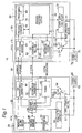
- FIG. 1 is a block diagram that shows a configuration of a programmed video-recording control system in accordance with one embodiment of the present invention.
- the programmed video-recording control system 10 of FIG. 1 comprises a set top box (hereinafter, referred to as "STB") 20 serving as a controller, a digital VTR 30 serving as a target, and an IEEE 1394 (80) serving as a digital interface for connecting these.
- STB set top box
- the controller is a control command transmitting apparatus to transmit outside a command
- the target is a control receiving apparatus to receive the command from the control command transmitting apparatus.
- the STB 20 comprises an operation section 25, a switch 54 for switching on and off the power supply to the operation section by connecting to a contact A or a contact B, a power supply controller 52 for controlling the switching of the switch 54, a main switch 55 for switching on and off the power supply to the entire STB 20, a user operation section 57 on which user provides designation to switch the switch 54, a delay circuit 58 which normally allows no current to flow, but when connected, is cut off after several seconds from the connection, and a power supply 56 which supplies power to the STB 20.
- the operation section 25 comprises a program setting section 40 for controlling programming process of recording programs for the target, a tuner 42 for receiving digital broad casting, a 1394 interface 43, a program executing section 48 for controlling execution of the program to the target, a programming list 50 in which program information is written, and a program manager 49 for carrying out writing and reading operations on and from the programming list 50.
- the 1394 interface 43 is provided with an 1394 isochronous transmitter 44 for transmitting commands and an 1394 asynchronous transmitter 46 for transmitting digital AV signals.
- the digital VTR 30 comprises a main section 35, a switch 74 for switching power supplies by connecting to contact A, B or C, a power supply controller 72 for controlling the switching of the switch 74, a main switch 75 for on/off switching the power supply to the entire digital VTR 30, a power supply 76 for supplying power to the digital VTR 30, a user operation section 77 on which the user provides designation to switch the switch 74, and a delay circuit 78 which normally allows no current to flow, but when connected, is cut after several seconds from the connection.
- the main section 35 comprises a 1394 interface 61, and a driving section 32 that contains motors and movable members for carrying out mechanical operations.
- the 1394 interface 61 includes a 1394 isochronous receiver 62 for receiving digital AV signals, and a 1394 asynchronous receiver 64 for receiving commands (for example, 1394 VCR command, 1394 tuner command) .
- the driving section 32 comprises a recording section 60 for recording digital AV signals on a recording medium, a programming list 68 in which program information is written, a program manager 66 for writing and reading operations on and from the programming list, and a program executing section 70.
- the main switch 55 of the STB 20 is on, the switch 54 is connected to the contact A, the main switch 75 of the digital VTR 30 is on, and the switch 74 is connected to the contact A.
- power is supplied to the power supply controllers 52 and 72 as well as to the user operation sections 57 and 77, however, no power is supplied to the operation section 25 of the STB 20 and the main section 35 of the digital VTR 30.
- the user switches the switch 54 to the contact B through the user operation section 57 so that the operation section 25 of the STB 20 is turned on, and also switches the switch 74 to the contact C through the user operation section 77 so that the main section 35 of the digital VTR 30 is turned on.
- the user inputs G code (licensed by Gemstar Japan Co., Ltd.) of a desired program to be programmed and recorded, to a program setting section 40.
- G codes of a plurality of programs may be inputted.
- the program setting section 40 converts the inputted G code into program information to transmit the information to the program manager 49 and the 1394 asynchronous transmitter 46.
- the above-mentioned program information is information containing a channel of a program to be recorded and recording start/end times and so on, and information which is used for controlling the setting of the video-recording programming of the digital VTR 30 from the STB 20.
- the program manager 49 writes the program information in the programming list 50.
- the program manager 49 reads the program information from the programming list 50, and transmits the program information to the program executing section 48.
- the program executing section 48 transmits control commands to the power supply controller 52 together with the program information.
- the 1394 asynchronous transmitter 46 transmits the program information transmitted from the program setting section 40 and commands which are obtained by adding headers etc. to the control command, to the digital VTR 30 with asynchronous communication through the IEEE 1394 (80).
- the power supply controller 52 switches the switch 54 to the contact A, thereby after a lapse of a predetermined time, for example, after a lapse of several seconds, power supply to the operation section 25 is cut off. Therefore, only the power supply controller 52 is on, and the other devices in the STB 20 (that is, the operation section 25) are off (hereinafter, this state is referred to as "a power saving state").
- the power supply to the STB 20 may be turned off by the user.
- the commands are sent to the program executing section 48 from the user operation section 57.
- the program executing section 48 reads out the next program information from the programming list 50 by the program manager 49, and transmits the next program information to the power supply controller 52.
- a certain period of time (for example, several seconds) is required until the transmission of the next program information to the power supply controller 52 is completed after the switch 54 has been switched to the contact A.
- the delay circuit 58 delays cutting off the power supply to the STB 20 so that the STB 20 is brought to the power saving state after completion of the transmission.
- the 1394 asynchronous receiver 64 takes out the program information from the commands transmitted from the STB 20, and transmits the information to the program manager 66. Upon receipt of the commands, the 1394 asynchronous receiver 64, if the commands are capable of being executed, transmits an accept response to the controller within 100 ms. Moreover, the program manager 66 writes the program information in the programming list 68. Moreover, the program manager 66 reads the program information from the programming list 68, and transmits the program information to the program executing section 70. The program executing section 70 transmits the next program information to the power supply controller 72, and also transmits control commands thereto. Based upon the control commands, the power supply controller 72 switches the switch 74 to the contact A. Therefore, the digital VTR 30 is brought into the power saving state with only the power supply controller 72 being on. Thus, the setting process for the video-recording programming is completed.
- the switch 74 may be switched to the contact A by the user.
- a command is sent from the user operation section 77 to the program executing section 70.
- the program executing section 70 reads out the next program information from the programming list 68 by the program manager 66, and transmits the next program information to the power supply controller 72.
- a certain period of time (for example, several seconds) is required until the transmission of the next program information to the power supply controller 72 is completed after the switch 74 has been switched to the contact A.
- the delay circuit 78 delays a shut down of the power supply to the STB 20 so that the STB 20 is brought to the power saving state after completion of the transmission.
- the digital VTR 30 receives the programming command including the program information from the STB 30 and can write the received program information in the programming list 68
- the digital VTR 30 transmits an access response within 100 ms.
- the STB 20 receives this response in the 1394 asynchronous transmitter 46.
- the STB 20 can confirm the fact that the program information is written in the programming list 68 so as to carry out the setting of the video-recording programming.
- program information to be written in the programming lists 50 and 68 is given in the following Table.
- channels, start times and end times of programs to be programmed and recorded are contained.
- CHANNEL RECORDING START TIME RECORDING END TIME 10 ch 2000/4/12 2000/4/12 7:00 PM 8:54 PM 2 ch 2000/4/12 2000/4/12 9:00 PM 10:00 PM
- Both of the power supply controllers 52 and 72 have built-in clocks, respectively. Based upon the start time of the video-recording programming contained in the program information, the power supply controller 52 switches the switch 54 of the STB 20 to the contact B several minutes before the recording start time, while the power supply controller 72 switches the switch 74 of the digital VTR 30 to the contact B. At this time, in the digital VTR 30, the 1394 asynchronous receiver 64 and the 1394 isochronous receiver 62 are respectively ready for receiving commands and digital AV signals, and the other devices are off. Hereinafter, this state of the digital VTR 30 is referred to as "a program executing standby state". In contrast, in the STB 20, all the devices are in operable states.
- the program executing section 48 having a built-in clock transmits a control command from the STB 20 to the digital VTR 30 by asynchronous communication several seconds before the recording start time of the set video-recording programming. If the 1394 asynchronous receiver 62 has received the control command which is operable, the 1394 asynchronous receiver 62 transmits an accept response to the STB 20 within 100 ms from the receipt. Moreover, the 1394 asynchronous receiver 62 transmits a control command to the power supply controller 72, and the power supply controller 72 switches the switch 74 to the contact C, thereby bringing all the devices for executing the programmed video-recording process in the digital VTR 30 into an operable state.
- the power supply controller 72 does not switch the switch 74 at the programmed video-recording start time which was set before. Therefore, even when the programmed video-recording start time is changed, no power is supplied to the driving section 32 which has a great power consumption, thereby making it possible to diminish time during which wasteful power is supplied.
- the program executing section 48 in the STB 20 transmits a control signal to the tuner 42.
- the tuner 42 selects the channel for the programmed program from digital broadcasting received through the antenna.
- the digital AV signal of the programmed program selected by the tuner 42 is transmitted to the 1394 isochronous transmitter 44.
- the 1394 isochronous transmitter 44 transmits the received digital AV signal to the digital VTR 30 by isochronous communication through the IEEE 1394 (80).
- the program executing section 48 transmits a recording start command to the digital VTR 30 with asynchronous communication through the IEEE 1394 (80).
- the digital broadcasting inputted to the tuner 42 is not limited to digital broadcasting received through the antenna, but may be, for example, digital broadcasting transmitted through a cable.
- the 1394 asynchronous receiver 64 receives the recording start command transmitted from the STB 20, and transmits the command to the program executing section 70. Moreover, the 1394 isochronous receiver 62 receives digital AV signals transmitted from the STB 20, and transmits the signal to the recording section 60. At this time, the program executing section 70 transmits the control signal to the recording section 60. The recording section 60 starts recording the programmed program to a video tape. In the same manner as the setting of the video-recording programming, in the case of executing the programmed video-recording process also, upon receipt of the recording start command from the STB 20 and the received command is operable, the digital VTR 30 transmits an accept response within 100 ms from the receipt. The STB 20 receives the response with the 1394 asynchronous transmitter 44, and thus it is possible to confirm the execution of the recording start command.
- the program executing section 48 in the STB 20 transmits a control signal to the tuner 42 to make the tuner 42 to terminate the receiving of the digital broadcasting. Moreover, the program executing section 48 transmits a recording end command to the digital VTR 30 with asynchronous communication through the IEEE 1394 (80).
- the 1394 asynchronous receiver 64 receives the recording end command transmitted from the STB 20, and transmits the command to the program executing section 70.
- the 1394 asynchronous receiver 64 transmits an accept response to the STB 20 within 100 ms from the receipt.
- the program executing section 70 transmits a control signal to the recording section 60 to make the recording section 60 terminate the recording process.
- the program executing section 70 reads out the next program information from the programming list 68, and transmits the recording end command to the power supply controller 72 together with the next program information.
- the power supply controller 72 switches the switch 74 to the contact A, and digital VTR 30 comes into the power saving state.
- the program executing section 48 reads out the next program information from the programming list 50, and transmits a programmed-recording end command to the power supply controller 52 together with the next program information. Based upon this programmed-recording end command, the power supply controller 52 turns the switch 54 off, thereby allowing the STB 20 to enter the power saving state.
- the STB 20 also receives an accept response from the digital VTR 30, it is possible to confirm the completion of the programmed-recording process of the digital VTR 30.
- FIG. 1 the digital AV signal and the command are illustrated as if they were transmitted from respective IEEEs 1394 (80). However, these drawings are given for convenience of explanation, and in fact, the digital AV signal and the command are transmitted through one IEEE 1394 (80).
- FIG. 2 is an explanatory drawing that explains states of packets that are transmitted through the IEEE 1394.
- the AV signals and so on are transmitted through isochronous packets 110, while in the asynchronous communication, the program information, control commands and so on are transmitted through asynchronous packets 120.
- One cycle contains an interval from a cycle start packet 100 to the next cycle start packet 100.
- the interval between the respective cycle start packets is basically 125 ⁇ sec. 100 ⁇ sec Of 125 ⁇ sec is used for isochronous communication, and the rest thereof is used for asynchronous communication.
- the isochronous packet 110 is always transmitted next to the cycle start packet 100, and the asynchronous packet 120 is transmitted between the isochronous packet 110 and the next cycle start packet 100.
- only one IEEE 1394 (80) can transmit all the AV signals including video signals and audio signals and control commands, and it is not necessary to use independently different interfaces as in the case of analog data transfer.
- the digital VTR 30 is controlled to be in the power saving state in which power supply to the sections other than the power supply controller 72 is cut off, a predetermined time before the recording start time.
- the digital VTR 30 is controlled to a program-executing standby state in which the 1394 interface 61b in addition to the sections other than the power supply controller 72 is supplied with power, a predetermined time before recording start time.
- the STB 20 it is possible to further reduce the power consumption by controlling the STB 20 to a power saving state a predetermined time before the recording start time in the standby state for the programmed process.
- IEEE 1394 (80) capable of bi-directional communications to the programmed video-recording control system 10 of the present invention allows the STB 20 to confirm the completion of setting of a video-recording programming or the completion of a programmed recording in the digital VTR 30.
- Fig. 3 shows a configuration of a programmed video-recording control system of this embodiment.
- the programmed video-recording control system of this embodiment comprises a digital VTR and a STB as same as the first embodiment.
- the digital VTR serves as the controller
- the STB serves as the target.
- the STB 20b and the digital VTR 30b of this embodiment have almost the same components as those of the first embodiment, but are different in the followings.
- the STB 20b of this embodiment has a 1394 asynchronous receiver 46b in the 1394 interface 43b, but has no program setting section 40.
- the digital VTR 30b has a 1394 asynchronous transmitter 64b in the 1394 interface 61b.
- a driving section 32b of the digital VTR 30b has a program setting section 65 which is connected between the 1394 asynchronous transmitter 64b and the program manager 66 in addition to components of the driving section 32 of the first embodiment.
- setting of video-recording programming is done on a side of the digital VTR 30b. That is, user makes the setting on the program setting section 65 of the digital VTR 30. Details of the setting of the video-recording programming by the user is the same as described in the first embodiment.
- the program setting section 65 transmits program information which is provided by the setting to the program manager 66 and the 1394 asynchronous transmitter 64b.
- the program manager 60 writes the program information to the programming list 68 and further transmits the program information to the program executing section 70.
- the program executing section 70 transmits the program information and a control command to the power supply controller 72.
- the power supply controller 72 switches the switch 74 to a contact A according to the control command, thereby cutting off power supply to a main section 35b predetermined time after switching. Accordingly, the digital VTR 30 is in a state (power saving state) in which only the power supply controller 72 is on and the main section 35b is not supplied with power.
- such a switching for cutting off the power supply to the main section 35b of the digital VTR 30b may be done by user operation. That is, user may switch the switch 74 to the contact A through the user operation section 77. In this time, the user operation section 77 transmits a command to the program executing section 70.
- the program executing section 70 controls the program manager 66 according to the command such that the next program information is read out from the programming list 68 and the read next program information is transmitted to the power supply controller 72.
- the 1394 asynchronous transmitter 64b transmits the program information transmitted from the program setting section 65 and a command which is obtained by adding header and so on to the control command to the STB 20b via IEEE1394 (80).
- the 1394 asynchronous receiver 46b retrieves the program information from the received command to transmit the retrieved information to the program manager 49.
- the program manager 49 writes the program information to the programming list 50 and transmits the information to the program executing section 48.
- the program executing section 48 transmits the next program information and the control command to the power supply controller 52.
- the power supply controller 52 switches the switch 74 to the contact A according to the control command. Then, only the power supply controller 52 is supplied with power, that is, STB 20b becomes the power saving state. Thus the setting of the video-recording programming is completed.
- the user may switch the switch 74 to the contact A through the user operation section 77.
- the user operation section 77 transmits a command to the program executing section 48 when the switch 74 is switched to the contact A.
- the program executing section 48 controls the switch 54 according to the command such that only the power supply controller 52 is on.
- the power supply controller 72 switches the switch 74 to the contact B several minutes before the recording start time according to the recording start time included in the program information.
- the power supply controller 52 switches the switch 54 to the contact B several minutes before the recording start time.
- the 1394 interface 43b is supplied with power.
- the 1394 asynchronous receiver 46b is in a state capable of receiving the command from the digital VTR 30, and the other devices are off. This state of the STB 20b is referred to as "the program-executing standby state".
- the digital VTR 30b is in a state in which all devices in the digital VTR 30b are executable.
- the program executing section 70 of the digital VTR 30b transmits a control command to the STB 20b with asynchronous communication several seconds before the recording start time of the video-recording programming setting.
- the 1394 asynchronous receiver 46b of the STB 20b transmits the control command to the program manager 49 and the program executing section 48.
- the program executing section 48 transmits a control command to the power supply controller 52 so as to switch the switch 54 to the contact C.
- all devices for programmed recording in the STB 20b become executable.
- the program executing section 70 in the digital VTR 30b transmits a command for tuning (referred to as "tuning command") to the STB 20 via the 1394 asynchronous transmitter 64b.
- tuning command a command for tuning
- the tuning command is transmitted to the tuner 42 via the 1394 asynchronous receiver 46b.
- the tuner 42 selects the channel for the recording-programmed program from received digital broadcasting.
- the digital AV signal of the recording-programmed program selected by the tuner 42 is transmitted to the digital VTR 30b via the 1394 isochronous transmitter 44 with isochronous communication.
- the STB 20 transmits an accept response to the digital VTR 30.
- the digital VTR 30 receives the tuning command and can confirm that the tuning command is executed based on the received tuning command.
- the program executing section 70 transmits a control signal to the recording section 60.
- the recording section 60 starts recording the recording-programmed program to a video tape according to the control signal.
- the STB 20b receives the tuning command from the digital VTR 30b when video-recording is started, and tunes according to the tuning command.
- program information including the tuning command may be received from the digital VTR 30b at the setting of the video-recording programming and the channel may be selected according to the tuning command received at the setting.
- the program executing section 48 sends a control signal for tuning to the tuner 42 at the recording start time.
- the program executing section 70 in the digital VTR 30b transmits a control signal to the STB 20b to terminate reception of the digital broadcasting.
- the tuner 42 terminates the reception of the digital broadcasting according to the control signal.
- the program executing section 48 reads the next program information from the programming list 50, and transmits next program information and a programmed-recording end command to the power supply controller 52. Based upon the programmed-recording end command, the power supply controller 52 switches the switch 54 to the contact A. Thus, power supply to the driving section 25b including the 1394 interface 43b is cut off after a predetermined time passes, and thus the STB 20 comes into the power saving state. It is noted that at the end of recording the STB 20b transmits the accept response to the digital VTR 30b.
- the program executing section 70 controls the recording section 60 to terminate video-recording. Thereafter, the program executing section 70 reads out the next program information from the programming list 68, and transmits the next program information and a command for terminating a recording to the power supply controller 72.
- the power supply controller 72 switches the switch 74 to connect the contact A, thereby the digital VTR 30 becoming in power saving state.
- the digital VTR 30 serves as the controller, while the STB 20b serves as the target, in which the digital VTR 30b controls the operation on the programmed video-recording of the STB 20b.
- the STB 20b is controlled to the power saving state in which all sections other than the power supply controller 52 are not supplied with power, until a predetermined time before the recording start time. Further at a predetermined time before the recording start time, the STB 20b is controlled to the program executing standby state in which power is supplied to the 1394 interface 43b for receiving a command as well as the sections other than the power supply controller 52.
- power consumption during the standby state for the programmed process can be reduced much.
- the STB(Set Top Box) as a broadcasting receiver and the digital VTR as a recorder are used for the controller and the target.
- a television incorporating a STB may be used as the broadcasting receiver, and a hard disc recorder or a DVD recorder which stores data may be used as the recorder.
- data described in BML Broadcast Markup Language
- the recorder may store the data transmitted from the receiver to a recording medium such as a hard disc or a DVD.
- video-recording is picked up in the above description as an example of the programmed process.
- the programmed process however is not limited to this, but includes the other process.
- a combination of the controller and the target is not limited to a combination of the broadcasting receiver and the recorder, but may be another combination of electric apparatuses in which the controller transmits the program information and power supply to a section for receiving a command in the target is controlled.
Landscapes
- Engineering & Computer Science (AREA)
- Multimedia (AREA)
- Signal Processing (AREA)
- Two-Way Televisions, Distribution Of Moving Picture Or The Like (AREA)
- Television Receiver Circuits (AREA)
Abstract
Description
| CHANNEL | RECORDING START TIME | |
| 10 ch | 2000/4/12 | 2000/4/12 |
| 7:00 PM | 8:54 PM | |
| 2 ch | 2000/4/12 | 2000/4/12 |
| 9:00 PM | 10:00 PM |
Claims (9)
- A programmed process control system (10, 10b) which executes a programmed process which is to be executed at a predetermined time set in advance, characterized bya first apparatus (20, 35b) for transmitting outside a command to instruct execution of the programmed process, anda second apparatus (35, 20b) for receiving the command to execute the programmed process, wherein the second apparatus (35, 20b) comprises:a command receiving section (64, 46b) for receiving the command;a program executing section (70, 48) for executing the programmed process according to the command; anda power supply controller (72, 52) for controlling power supply to the command receiving section (64, 46b) according to execution of the programmed process.
- The system according to claim 1, wherein the power supply controller (72, 52) controls the power supply to the command receiving section (64, 46b) such that the power supply is started a first predetermined time before a recording start time of executing the programmed process.
- The system according to claim 1, wherein the power supply controller (72, 52) controls the power supply to the command receiving section (64, 46b) such that the power supply is cut off after a second predetermined time from an end time of executing the programmed process.
- The system according to claim 1, wherein the first apparatus (20) outputs a predetermined data, and the second apparatus (30) receives the predetermined data and applies a predetermined process to the received data.
- The system according to claim 1, wherein the second apparatus (20b) outputs a predetermined data, and the first apparatus (30b) receives the predetermined data and applies a predetermined process to the received data.
- The system according to claim 1, wherein IEEE1394 is used for interface (80) between the fist apparatus (20 or 35b) and the second apparatus (35 or 20b).
- An apparatus (35, 20b) for receiving a command to instruct execution of a programmed process which is to be executed at a predetermined time set in advance from an external apparatus, characterized by:a command receiving section (64, 46b) for receiving the command;a program executing section (70, 48) for executing the programmed process according to the command; anda power supply controller (72, 52) for controlling power supply to the command receiving section according to execution of the programmed process.
- The apparatus according to claim 7, wherein the power supply controller (72, 52) controls the power supply to the command receiving section (64, 46b) such that the power supply is started a first predetermined time before a recording start time of executing the programmed process.
- The apparatus according to claim 7, wherein the power supply controller (72, 52) controls the power supply to the command receiving section (64, 46b) such that the power supply is cut off after a second predetermined time from an end time of executing the programmed process.
Applications Claiming Priority (2)
| Application Number | Priority Date | Filing Date | Title |
|---|---|---|---|
| JP2000172182 | 2000-06-08 | ||
| JP2000172182 | 2000-06-08 |
Publications (2)
| Publication Number | Publication Date |
|---|---|
| EP1162838A2 true EP1162838A2 (en) | 2001-12-12 |
| EP1162838A3 EP1162838A3 (en) | 2003-01-22 |
Family
ID=18674624
Family Applications (1)
| Application Number | Title | Priority Date | Filing Date |
|---|---|---|---|
| EP01304759A Withdrawn EP1162838A3 (en) | 2000-06-08 | 2001-05-30 | Programmed process control system |
Country Status (1)
| Country | Link |
|---|---|
| EP (1) | EP1162838A3 (en) |
Family Cites Families (2)
| Publication number | Priority date | Publication date | Assignee | Title |
|---|---|---|---|---|
| JP2811670B2 (en) * | 1988-01-12 | 1998-10-15 | ソニー株式会社 | Receiving machine |
| KR970005996B1 (en) * | 1994-02-03 | 1997-04-22 | 엘지전자 주식회사 | Green power apparatus and control method |
-
2001
- 2001-05-30 EP EP01304759A patent/EP1162838A3/en not_active Withdrawn
Also Published As
| Publication number | Publication date |
|---|---|
| EP1162838A3 (en) | 2003-01-22 |
Similar Documents
| Publication | Publication Date | Title |
|---|---|---|
| EP1057330B1 (en) | Apparatus for reproducing programs | |
| US7684672B2 (en) | Broadcast storage system with reduced user's control actions | |
| US6252630B1 (en) | Receiver and receiving method | |
| EP1191790B1 (en) | Program-signal recording and reproducing apparatus | |
| JP3480923B2 (en) | Device control method on network and video device using this control method | |
| JPH11164254A (en) | Television receiver | |
| KR20060127851A (en) | Method and apparatus for providing simplified peer-to-peer recording | |
| JPH09163298A (en) | Video equipment | |
| EP1584188A2 (en) | Recording start and stop | |
| EP1162838A2 (en) | Programmed process control system | |
| JP2004349790A (en) | Recording and playback device | |
| JP4701523B2 (en) | Remote control system | |
| JP4232452B2 (en) | Video / audio signal processor | |
| US7206498B2 (en) | Recorder | |
| JP3720347B2 (en) | Display device, center device, video display system, display device control method, center device control method, display device control program, center device control program, and recording medium recording the program | |
| JP2002152652A (en) | Method and device for receiving, recording and reproducing broadcast | |
| JP2002063749A (en) | Reservation processing system | |
| JP2008236282A (en) | Broadcast program recording and playback device | |
| KR20050090286A (en) | Combo-system capable of reserved recording of analog or digital broadcasting signal through one menu screen and method thereof | |
| US20060127033A1 (en) | Apparatus for recording and reproducing data and recording method therefor | |
| JPH10271432A (en) | Video recording device and playback device | |
| US6204841B1 (en) | Programmed recording device and method of cable television broadcasting signal | |
| WO1998037463A1 (en) | A system and method for controlling a peripheral device | |
| KR100284200B1 (en) | Time record control method of VCR | |
| EP2144436B1 (en) | Video data outputting |
Legal Events
| Date | Code | Title | Description |
|---|---|---|---|
| PUAI | Public reference made under article 153(3) epc to a published international application that has entered the european phase |
Free format text: ORIGINAL CODE: 0009012 |
|
| AK | Designated contracting states |
Kind code of ref document: A2 Designated state(s): AT BE CH CY DE DK ES FI FR GB GR IE IT LI LU MC NL PT SE TR |
|
| AX | Request for extension of the european patent |
Free format text: AL;LT;LV;MK;RO;SI |
|
| PUAL | Search report despatched |
Free format text: ORIGINAL CODE: 0009013 |
|
| AK | Designated contracting states |
Kind code of ref document: A3 Designated state(s): AT BE CH CY DE DK ES FI FR GB GR IE IT LI LU MC NL PT SE TR |
|
| AX | Request for extension of the european patent |
Free format text: AL;LT;LV;MK;RO;SI |
|
| 17P | Request for examination filed |
Effective date: 20030708 |
|
| AKX | Designation fees paid |
Designated state(s): DE FR GB |
|
| RAP1 | Party data changed (applicant data changed or rights of an application transferred) |
Owner name: PANASONIC CORPORATION |
|
| STAA | Information on the status of an ep patent application or granted ep patent |
Free format text: STATUS: THE APPLICATION IS DEEMED TO BE WITHDRAWN |
|
| 18D | Application deemed to be withdrawn |
Effective date: 20111201 |