EP1162830A2 - Method and apparatus for electronically distributing motion panoramic images - Google Patents
Method and apparatus for electronically distributing motion panoramic images Download PDFInfo
- Publication number
- EP1162830A2 EP1162830A2 EP01303774A EP01303774A EP1162830A2 EP 1162830 A2 EP1162830 A2 EP 1162830A2 EP 01303774 A EP01303774 A EP 01303774A EP 01303774 A EP01303774 A EP 01303774A EP 1162830 A2 EP1162830 A2 EP 1162830A2
- Authority
- EP
- European Patent Office
- Prior art keywords
- tiles
- tile
- panoramic image
- view
- quality
- Prior art date
- Legal status (The legal status is an assumption and is not a legal conclusion. Google has not performed a legal analysis and makes no representation as to the accuracy of the status listed.)
- Withdrawn
Links
Images


Classifications
-
- H—ELECTRICITY
- H04—ELECTRIC COMMUNICATION TECHNIQUE
- H04N—PICTORIAL COMMUNICATION, e.g. TELEVISION
- H04N7/00—Television systems
- H04N7/18—Closed-circuit television [CCTV] systems, i.e. systems in which the video signal is not broadcast
-
- H—ELECTRICITY
- H04—ELECTRIC COMMUNICATION TECHNIQUE
- H04N—PICTORIAL COMMUNICATION, e.g. TELEVISION
- H04N19/00—Methods or arrangements for coding, decoding, compressing or decompressing digital video signals
- H04N19/10—Methods or arrangements for coding, decoding, compressing or decompressing digital video signals using adaptive coding
- H04N19/102—Methods or arrangements for coding, decoding, compressing or decompressing digital video signals using adaptive coding characterised by the element, parameter or selection affected or controlled by the adaptive coding
- H04N19/103—Selection of coding mode or of prediction mode
-
- H—ELECTRICITY
- H04—ELECTRIC COMMUNICATION TECHNIQUE
- H04N—PICTORIAL COMMUNICATION, e.g. TELEVISION
- H04N19/00—Methods or arrangements for coding, decoding, compressing or decompressing digital video signals
- H04N19/10—Methods or arrangements for coding, decoding, compressing or decompressing digital video signals using adaptive coding
- H04N19/134—Methods or arrangements for coding, decoding, compressing or decompressing digital video signals using adaptive coding characterised by the element, parameter or criterion affecting or controlling the adaptive coding
- H04N19/162—User input
-
- H—ELECTRICITY
- H04—ELECTRIC COMMUNICATION TECHNIQUE
- H04N—PICTORIAL COMMUNICATION, e.g. TELEVISION
- H04N19/00—Methods or arrangements for coding, decoding, compressing or decompressing digital video signals
- H04N19/10—Methods or arrangements for coding, decoding, compressing or decompressing digital video signals using adaptive coding
- H04N19/134—Methods or arrangements for coding, decoding, compressing or decompressing digital video signals using adaptive coding characterised by the element, parameter or criterion affecting or controlling the adaptive coding
- H04N19/164—Feedback from the receiver or from the transmission channel
-
- H—ELECTRICITY
- H04—ELECTRIC COMMUNICATION TECHNIQUE
- H04N—PICTORIAL COMMUNICATION, e.g. TELEVISION
- H04N21/00—Selective content distribution, e.g. interactive television or video on demand [VOD]
- H04N21/20—Servers specifically adapted for the distribution of content, e.g. VOD servers; Operations thereof
- H04N21/21—Server components or server architectures
- H04N21/218—Source of audio or video content, e.g. local disk arrays
- H04N21/21805—Source of audio or video content, e.g. local disk arrays enabling multiple viewpoints, e.g. using a plurality of cameras
-
- H—ELECTRICITY
- H04—ELECTRIC COMMUNICATION TECHNIQUE
- H04N—PICTORIAL COMMUNICATION, e.g. TELEVISION
- H04N21/00—Selective content distribution, e.g. interactive television or video on demand [VOD]
- H04N21/20—Servers specifically adapted for the distribution of content, e.g. VOD servers; Operations thereof
- H04N21/23—Processing of content or additional data; Elementary server operations; Server middleware
- H04N21/234—Processing of video elementary streams, e.g. splicing of video streams, manipulating MPEG-4 scene graphs
- H04N21/2343—Processing of video elementary streams, e.g. splicing of video streams, manipulating MPEG-4 scene graphs involving reformatting operations of video signals for distribution or compliance with end-user requests or end-user device requirements
- H04N21/234345—Processing of video elementary streams, e.g. splicing of video streams, manipulating MPEG-4 scene graphs involving reformatting operations of video signals for distribution or compliance with end-user requests or end-user device requirements the reformatting operation being performed only on part of the stream, e.g. a region of the image or a time segment
-
- H—ELECTRICITY
- H04—ELECTRIC COMMUNICATION TECHNIQUE
- H04N—PICTORIAL COMMUNICATION, e.g. TELEVISION
- H04N21/00—Selective content distribution, e.g. interactive television or video on demand [VOD]
- H04N21/60—Network structure or processes for video distribution between server and client or between remote clients; Control signalling between clients, server and network components; Transmission of management data between server and client, e.g. sending from server to client commands for recording incoming content stream; Communication details between server and client
- H04N21/65—Transmission of management data between client and server
- H04N21/658—Transmission by the client directed to the server
- H04N21/6587—Control parameters, e.g. trick play commands, viewpoint selection
-
- H—ELECTRICITY
- H04—ELECTRIC COMMUNICATION TECHNIQUE
- H04N—PICTORIAL COMMUNICATION, e.g. TELEVISION
- H04N21/00—Selective content distribution, e.g. interactive television or video on demand [VOD]
- H04N21/80—Generation or processing of content or additional data by content creator independently of the distribution process; Content per se
- H04N21/81—Monomedia components thereof
- H04N21/816—Monomedia components thereof involving special video data, e.g 3D video
-
- H—ELECTRICITY
- H04—ELECTRIC COMMUNICATION TECHNIQUE
- H04N—PICTORIAL COMMUNICATION, e.g. TELEVISION
- H04N23/00—Cameras or camera modules comprising electronic image sensors; Control thereof
- H04N23/58—Means for changing the camera field of view without moving the camera body, e.g. nutating or panning of optics or image sensors
Definitions
- the present invention relates to the field of image processing and data distribution.
- the present invention discloses methods and apparatus for processing, transmitting, and post-processing panoramic image information.
- Panoramic cameras capture a much wider field of field.
- a panoramic camera constructed using an optical "fish-eye" lens may capture at most a 210-degree field of view.
- a panoramic camera constructed with a catadioptric lens captures a full 360-degree panoramic image. With a large panoramic field of view, individual panoramic image viewers can decide what they will focus on.
- Another difficulty with motion panoramic images is that a user often desires to rapidly pan the view from one area of the panorama to another. Because of the limited bandwidth available for sending the panoramic image from a motion panoramic image server to a client system, such rapid pan operations result in significant latency delays and/or temporal tearing between the time the user performs the pan operation and the display of the resulting view. Thus, it would be desirable to utilize the available bandwidth to provide both high-quality data (for the portion of the motion panoramic image being viewed) and lower-quality data (for the portions of the motion panoramic image that are not being viewed and dependent on the likelihood of that portion being viewed).
- One embodiment comprises an electronic image distribution apparatus for distributing motion panoramic images.
- the main portion of the apparatus is a motion panoramic image server that has a source of motion panoramic images.
- the source of panoramic image frames can be a motion panoramic image playback device or a connection to a motion panoramic camera system.
- the motion panoramic image server transforms the panoramic image frames into an intermediate planar representation that is more conducive for electronic transmission.
- the motion panoramic image server then transmits the motion panoramic images to client systems.
- one preferred embodiment discloses methods and apparatus for obtaining portions of a panorama over a limited bandwidth link.
- the invention uses an encoder array to multiply encode the panorama into tiles that have different characteristics.
- the computer that uses the encoded data to present a view into the panorama subscribes to the tiles containing the encoded data.
- the tiles that are subscribed-to are selected based on the bandwidth available to transfer the tiles and the quality of the data in the tiles.
- the computer selects higher-quality tiles near the viewpoint and lower-quality tiles dependent on the distance the tile is from the viewpoint. As the viewpoint is altered (such as by a pan operation), the computer dynamically adjusts the tile subscription to present a quality image.
- the pan operation moves the viewpoint such that data from lower-quality tiles is required to present the view
- the data is presented using the lower-quality data until the higher-quality data resulting from the new tile subscription arrives.
- the presentation of the lower-quality data can be reduced or avoided by limiting the range of an allowable pan, by predicting a future need for high-quality tiles based on a pan history, by providing tiered tiles near the viewpoint to reduce temporal and other presentation artifacts.
- Another preferred embodiment provides an entire panorama containing distributed-quality data to the client computer.
- the panorama is encoded such that a portion of the panorama is encoded for high-quality, other portions of the panorama are encoded for reduced-quality, and yet other portions of the panorama are encoded for low-quality (one skilled in the art will understand that more than three levels of quality can be used within the panorama).
- Multiple encodings of the panorama differing by the placement of the relative quality portions are provided to the client.
- the client is thus able to select the panorama encoding that includes a high-quality portion responsive to the client's viewpoint.
- the viewpoint moves away from the high-quality portion of the currently selected panorama encoding, the client subscribes to a different panorama encoding that includes a high-quality portion at responsive to the new viewpoint.
- Preferred embodiments include (without limitation) system methods, client computer side methods, server computer side methods, server apparatus, client apparatus, and computer program products for the server computer and the client computer.
- a method and apparatus for compressing and distributing motion panoramic images is disclosed.
- specific nomenclature is set forth to provide a thorough understanding of the present invention.
- these specific details are not required in order to practice the present invention.
- the present invention's method of distributing panoramic images has been described with reference to the Internet.
- other types of digital information distribution systems for example private data networks and satellite systems
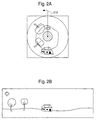
- Figure 1 illustrates an embodiment of one possible 360-degree panoramic camera system.
- the image capture mechanism 150 of the panoramic camera system captures an angular image of the surrounding panorama that is reflected off the main reflector 110 . More details about the panoramic camera system of Figure 1 can be found in the copending patent application entitled “Panoramic Camera”, filed June 11, 1997, having serial number 08/872,525.
- Figure 2a illustrates an example of a panoramic image captured as an annular image.
- the surrounding panorama is distorted by the main reflector having radial symmetry such that the surrounding represented as a two-dimensional annular image.
- the shape of the main reflector transforms the standard rectangular coordinate system of the image into a polar coordinate system.
- the annular image may be unwrapped to create an intermediate planar representation. The unwrapping is performed using a geometric transformation operation.
- Figure 2b illustrates how the annular image of Figure 2a appears after the images are geometrically transformed from the annular representation to a rectangular intermediate planar representation.
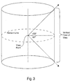
- the panoramic camera system of Figure 1 captures an entire 360-degree image of the surrounding horizon as illustrated in Figure 3.
- the panoramic camera system captures a panoramic image that includes objects as low as 50 degrees below the horizon and objects as high as 50 degrees above the horizon.
- alternate panoramic camera systems may capture a full spherical panoramic view, a partial 180-degree hemispherical view, or any other panoramic view.
- a panoramic image may be constructed by combining a mosaic of conventional images captured with conventional camera systems. For example, eight conventional cameras can be used to capture images from eight different directions. Those images are then combined together to create a single panoramic image.
- the image capture mechanism 150 of the panoramic camera of Figure 1 is a motion image capture mechanism such as a charged coupled device (CCD) or a film-based motion picture image capture system
- CCD charged coupled device
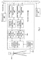
- FIG. 4 illustrates one possible embodiment of an electronic motion panoramic image capture system.
- a panoramic camera system 405 captures a series of panoramic annular image frames with an electronic image capture mechanism.
- the electronic image capture mechanism can be a charged coupled device image capture mechanism or CMOS image sensor that generates digitized panoramic annular image frames.
- the panoramic annular image frames are transmitted from panoramic camera system 405 to a panoramic image server 400 across a high bandwidth communication link 402.
- the communication link must be high bandwidth since each panoramic annular image frame contains a very large amount of information and, to provide a flicker-free motion image, several panoramic images must be transmitted each second.
- motion panoramic image capture systems may also be used.
- a motion panoramic capture system may be created with two motion picture camera systems pointing in opposite directions wherein each motion picture camera system is equipped with a fisheye lens that captures at least a 180 degree hemispherical field of view.
- each motion picture camera system is equipped with a fisheye lens that captures at least a 180 degree hemispherical field of view.
- two distorted fisheye images from each hemispherical view would need to be "stitched" together to create a single panoramic image.
- the full panoramic annular image frames generated by the panoramic camera system (such as panoramic camera system 405 of Figure 4) are so large that a very high bandwidth link is needed to transmit full motion images to a recipient.
- Such high bandwidth links are rare and expensive.
- more bandwidth efficient methods of distributing panoramic images are needed.
- the present invention introduces two different methods of distributing motion panoramic images.
- a first method divides panoramic images into tiles and transmits only the tiles needed to construct a desired image.
- a second method described in a later section, divides panoramic images into individual tiles and then transmits all the tiles on different multicast channels.
- the present invention first proposes a selective tile transmission system.
- a server computer system divides each panoramic frame into tiles.
- the tile size and shape are preferably selected in such a manner that is dependent upon a coordinate system used by the format used to transmit the tiles. Then, the tiles needed to construct an image on a client computer system are transmitted from the server system to individual clients.
- the server system transforms each incoming panoramic image frame into an intermediate planar representation. This transformation step is not necessary but provides certain advantages.
- the selective tile transmission system will be described with reference to a system that performs this transformation in Figures 4, 5, 6, 7, 8 and 9.
- a panoramic annular image transformation system 417 "unwraps" annular panoramic image frames into an intermediate planar representation.
- the intermediate planar representation is more convenient for generating images suitable for viewing. Specifically, the intermediate format should require fewer calculations to generate a final rectangular projection.
- the incoming annular panoramic image data is geometrically transformed into a spherical coordinate system with a spherical projection representation.
- a single frame of the image data may be viewed with the Live Picture viewer from Live Picture, Inc.
- Figure 5A conceptually illustrates a spherical data format wherein the view of the surroundings is projected onto a sphere surrounding a viewpoint.
- the incoming annular panoramic image data is geometrically transformed into a cylindrical coordinate system in a cylindrical projection representation.
- An image transformed into a cylindrical coordinate system may be viewed with the QuickTime VR viewer created by Apple Computer, Inc.
- Figure 3 conceptually illustrates a cylindrical data format wherein the view of the surroundings is projected onto a cylinder surrounding a viewpoint.
- the system of the present invention divides the intermediate planar representation into individual tiles.
- the size of the tiles are dependent upon the coordinate system of the intermediate planar representation.
- the tiles may be spatially variant.
- the size of the tiles may further be dependent upon the client system that will be displaying the panoramic image data.
- each client uses a different process ( 441 or 445 ) to divide intermediate planar representations into tiles since each client may use different client sizes.
- the size of the tiles are fixed such that a single process (illustrated as dotted box 449 ) may be used to divide an intermediate planar representation into individual tiles.
- Figure 5A illustrates a conceptual diagram of the spherically encoded intermediate planar representation.
- the spherically encoded intermediate planar representation represents the surrounding world as image data mapped onto a sphere.
- the sphere is broken into individual bands on sphere A, B, C, D, E, and F. Note that the bands near the "equator" of the spherically encoded intermediate planar representation contain more data than the bands closer to the "poles.”
- the image data is represented by individual bands that are divided into individual tiles as illustrated in Figure 5B .
- the graphical data representation of Figure 5C also matches the cylindrical data format of Figure 3.
- the data format of Figure 5B may be used and provides certain advantages (such as a more compact data format) this document will focus on the format of Figure 5C to simplify the description.
- a first row of tiles covers from the horizon line to thirty degrees above the horizon.
- a second row of tiles covers from thirty degrees above the horizon to forty-two degrees above the horizon.
- a third, top, row of tiles covers the band from forty-two degrees above the horizon to fifty degrees above the horizon.
- the same angular divisions are used to divide the space below the horizon.
- the row size divisions are nonlinear and widest at the horizon since users are usually most interested in views near the horizon. However, different angular divisions, such as linear angular divisions, may also be used.
- a tile fetching program ( 440 and 443 ) fetches tiles for transmission to the client system.
- the tile-fetching program only selects the tiles needed to create a view on a client computer system.
- the client computer system determines which tiles are needed and sends a request that specifies these tiles.
- the fetched tiles are transmitted using a tile-streaming program ( 460 and 463 ). By transmitting only the tiles needed to create a view on the client computer system, the system of the present invention limits the amount of information that must be transmitted from a panoramic image source server to a panoramic image client display.
- a low resolution "zoomed back" initial set of tiles may be used for panning around a panoramic image.
- the low-resolution initial tiles would encompass a large angular view.
- a higher resolution set of tiles could then be selected.
- Figures 5D, 5E and 5F illustrate one possible embodiment where a panoramic image space has been divided into three tiers of magnification.
- An initial "zoomed back" tile magnification intermediate planar representation is presented in Figure 5D .
- the lower resolution intermediate planar representation of Figure 5D is used first.
- the client software "zooms in” by fetching tiles from the next higher resolution intermediate planar representation displayed in Figure 5E . If even greater resolution is needed, the client software "zooms in” further by fetching tiles from Figure 5F .
- the pixel resolution of the individual tiles of Figures 5D, 5E and 5F is the same such that the individual tiles take up the same amount of screen space but provide successively greater resolution.
- the initial panoramic image frames need not be transformed into an intermediate planar representation before division into individual tiles.
- the intermediate planar representation transformation is usually performed since the transformation is used to put the image into a format that can be used to quickly generate an image for display with minimal processing.
- the raw panoramic image frames may immediately be divided into tiles and transmitted.
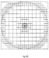
- Figure 5G illustrates a raw panoramic annular image frame from the panoramic camera system of Figure 1.
- the raw panoramic annular image is divided into tiles.
- the raw panoramic annular image is divided into square tiles that are small near the center since a small tile covers a wide image area in the annular format.
- the middle part of the annular disk is divided into larger tiles.
- the outside of the annular disk is divided into smaller tiles since a narrow strip of tiles is needed when constructing a view that uses information from the edge of the annular disk.
- the tiles are spatially variant.
- Figure 6A illustrates an example of a client system view into a panoramic image.
- client view 630 represents a view into an unwrapped panoramic image 610 requested by a client computer system.
- the view is distorted since the view is illustrated within the spherical coordinate space.
- a server such as server 400 transmits tiles 621, 623, 625, and 627.
- Each tile 621, 623, 625, and 627 is compressed before transmission to further reduce the amount of information that needs to be transmitted.
- Figure 6B illustrates how the four tiles 621, 623, 625 , and 627 transmitted from the server are used to construct the client view 630 on a client computer system. (The four tiles 621, 623, 625, and 627 appear distorted since the tiles are displayed in the rectangular projection coordinate space of Figure 6B.)
- the client system begins requesting tiles that are just slightly out of a current view when a view nears the edge of a tile in case the user moves further in that direction.
- the client system would begin requesting tiles 628 and 629 when the view shifts a little further to the right.
- the tile-fetching program in the server would fetch and transmit tiles 628 and 629 to the client system.
- tiles 623, 628, 627, and 629 would be used to construct the shifted client view in the client system.
- the client computer system is responsible for determining when the out of view tiles are needed and when they should be transmitted.
- the client system makes this determination by examining factors such as how fast the user is moving the view, the latency of the connection with the server, and the parameters that define the view.
- the client computer system transmits a list of desired tiles to the server wherein the list of desired tiles defines which tiles should be transmitted by the server to the client computer system.
- a user may quickly shift a view from a first view position 730 to a second view position 740.
- the first view position 730 was being rendered with tiles 721, 723, 725, and 727 that were sent by a server.
- the new second view position 740 requires tiles 751, 753, 755, and 757 that were not being transmitted.
- the present invention occasionally transmits a highly compressed version of the full panoramic image intermediate planar representation.
- the highly compressed panoramic image intermediate planar representation is only transmitted once every 30 or so normal frames.
- the client renders a view from the most recently received highly compressed panoramic image intermediate planar representation. This newly rendered view will not be in the normal resolution since it is being rendered from the highly compressed panoramic image intermediate planar representation.
- the server will begin transmitting the tiles needed at the new view location.
- the server will begin transmitting tiles 751, 753, 755, and 757.
- tiles 751, 753, 755, and 757 are received by the client computer system, the image rendered from the most recently received highly compressed panoramic image intermediate planar representation will be replaced with an image rendered from tiles 751, 753, 755, and 757.
- the new view image will become clearer once the server "catches up" to the users sudden view change.
- a sudden movement may not move the view completely away from the currently available tiles. For example, a movement may place the view partially on tiles that are available and partially on tiles that are not available. In such a situation, the portion of the view that is located on available tiles can be rendered at the resolution of those tiles and the remainder of the view will be rendered using the highly compressed version. Similarly, if the user is "zoomed in" on high resolution tiles and the user moves quickly away from the currently available high resolution tiles, the view may be constructed using the tile from the next lower resolution tier if that tile is still available.
- Figures 8 and 9 provide detailed flow diagrams that fully describe how the electronic image distribution system of Figure 4 operates.
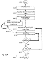
- Figure 8 illustrates a flowchart describing one embodiment wherein a panoramic motion image server system and a client system negotiate a connection.
- a standard connection can be used such that there is no negotiation of connection parameters.
- Figure 9 describes how a server system transmits image tiles to a client system.
- Figure 4 illustrates one embodiment of a motion panoramic image client-server system wherein the bandwidth is conserved by dividing panoramic images into tiles.
- the present invention conducts a client-server negotiation.
- the server system determines the characteristics of the client before determining how the client-server system will operate.
- Figure 8 illustrates a flow diagram describing the method of negotiating the client-server motion panoramic image connection.
- a client initiates a connection to a panoramic image server at step 810.
- the panoramic image server requests information that describes the display characteristics of the client.
- the server may request the client's frame buffer size, the client's frame buffer color characteristics, the size of the panoramic image view window, and other information relevant to the display of images on the client system.
- the motion panoramic image server may also request information describing the processing abilities of the client. For example, the panoramic image server may request the processor type, the processor speed, and the amount of main memory available.
- the client responds to the server's by sending this information to the motion panoramic image server at step 830.
- the motion panoramic image server uses the collected information to determine how the server will serve the client.
- One specific parameter that the server must decide is how to divide the unwrapped panoramic intermediate planar representation into tiles. Specifically, the size of the individual tiles will be determined.
- the motion panoramic image server may also determine the video frame-rate, a type of compression to use, and a processing-task division based upon the network connection speed and quality, the capabilities of the client system, and the current and anticipated processing load of the image server.
- the motion panoramic image server After determining the parameters of the motion panoramic image connection, the motion panoramic image server transmits the connection parameters to the client system at step 850.
- the client system will use the parameters to determine how the client system will display motion panoramic images.
- the client After the client and server have negotiated the motion panoramic image connection, the client begins requesting motion panoramic image information from the server system at step 860 .
- the server begins transmitting motion panoramic image tiles to the client system at step 870 . Since the connection to each client is uniquely calibrated, the server will transmit panoramic image information to each different client in a manner that is specific to that particular client. The server will continue transmitting motion panoramic images until the client requests the server to stop sending images at step 880.
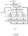
- Figure 9 describes how the motion panoramic image server transmits the information needed to construct a view within a motion panoramic image on a client system. Thus, Figure 9 describes in detail what occurs during the steps 860 and 870 of Figure 8.
- the first step that the motion panoramic image server must perform is transforming a panoramic image frame into one or more intermediate planar representations.
- the exact method of transforming a panoramic image frame is dependent on the type of camera system used. For example, a system built using the panoramic camera system of Figure 1 would perform a geometric transformation to transform the annular panoramic image frame into the selected intermediate planar representation. If a fisheye lens panoramic camera system were used, a different geometric transformation would transform the distorted fisheye image into the desired intermediate planar representation. All subsequent actions are performed on the transformed intermediate planar representation.
- the source panoramic image data is transformed into more than one intermediate planar representation of different resolutions.
- the source panoramic image data can be transformed into low, medium, and high-resolution intermediate planar representations as illustrated in Figures 5D, 5E and 5F.
- the method determines if a highly compressed version of the full panoramic image frame should be transmitted.
- a highly compressed version of the full panoramic image frame is transmitted occasionally to handle sudden movements of the client's view.
- the motion panoramic image server transmits a highly compressed version of the full panoramic image frame during first and every N th subsequent frame.
- the method proceeds to step 970 where the full panoramic image frame is compressed.
- the motion panoramic image server begins transmitting the highly compressed version of the full panoramic image frame.
- the transmission of the highly compressed version of the full panoramic image frame may occur all at once.
- the highly compressed version of the full panoramic image frame may be transmitted concurrently along with individual image tiles such that individual image tiles are not delayed.
- the one or more intermediate planar representation frames are divided into individual tiles as illustrated in Figures 5D, 5E and 5F.
- the size of the individual tiles is the size that was negotiated during the connection process described in the flow diagram of Figure 8.
- the server fetches and transmits the tiles needed to create the client's view at step 940.
- Each tile is compressed before transmission to conserve bandwidth and decrease latency.
- the client will use the transmitted tiles to construct an image.
- the server method determines if the client system is done viewing the motion panoramic image. If the client is not done, the method proceeds back to step 960.
- Figure 10 illustrates a flow diagram describing a method that a client system may follow to receive information and render an image. It should be noted that Figure 10 only illustrates one possible embodiment of a client system and that significant variations can be created. For example, several of the steps described in Figure 10 such as receiving tiles and rendering an image may be performed concurrently. Alternatively, less processing could be performed in the client system and more processing could be performed in the server.
- the client receives any and all requested panoramic image tiles and highly compressed full panoramic images transmitted by the server.
- the client attempts to render an image for the current view position. Ideally, the view will be rendered with the tiles needed for the view. However, if the client does not have the desired tiles, then the client renders an image of the current view using the available tiles for the view, tiles from lower resolution tiers, and the most recently received version of the highly compressed full panoramic image.
- the client system After rendering an image frame, the client system accepts input from a user at step 1030.
- the client system may accept input, such as directional commands from a computer mouse, that pans the view within the panoramic image.
- the client may also accept commands that zoom-in and change the vertical viewing angle.
- the client system then processes the user input to the server system at step 1030 to determine a next view position.
- the client system determines if the input specifies that the user is done viewing the panoramic image information.
- the client panoramic image-rendering program will terminate when the user no longer wishes to view the panoramic image.
- the client system determines the frame tiles that are needed to create the new view position.
- the client system also determines if it should request tiles that are just out of the current view but are likely to be needed in the future. Specifically, the client determines if the current view is near the edge of a tile. If the client's view is near the edge of a tile, then the client will request tiles that are just outside of the client's current view. The tiles just out of view are requested such that if the client moves the view beyond the edge of the tile, then the client will be able to create a view without having to request and wait for the server to then send the needed tile.
- the client anticipates small view movements and is prepared to generate a view. However, if the user makes a sudden large view change, then the client rendering engine can always fall back to the highly compressed version of the full panoramic image.
- the client system determines if any currently requested tiles are no longer needed. Tiles that are no longer needed consume valuable bandwidth such that the client system should unsubscribe from tiles that are no longer needed.
- the client system determines at step 1060 if the needed tiles have already been requested and if there are no unnecessary tiles on request. If the needed tiles have already been requested and there are no unnecessary tiles on request, then the client system does not need to change the tile subscriptions. However, if new tiles are needed or currently subscribed tiles are no longer needed, then the client system sends a request to the server at step 1070 that changes the tile subscription.
- the client system determines if any new frame tiles or compressed panoramic image frames have been received. If new frames have been received, then the method proceeds back to step 1010 to accept the new frames. Otherwise, the method proceeds back to step 1020 to render a new view image using the currently available tiles and the highly compressed full panorama image information. A different image may be generated from the same frame information if the user has shifted the view.
- the panoramic image intermediate planar representation is divided into overlapping tiles.
- An example of this is provided in Figure 11.
- a degree of hysteresis is provided such that small back and forth view changes will not cause the client system to oscillate requests for new tiles.
- the selective tile transmission system described in the previous section provides a useful method of delivering motion panoramic image information in a unicast environment where each client receives a unique individual data stream.
- each client since the motion panoramic server must send out a unique data stream to each client, there will be a significant amount of redundant information being transmitted.
- the present invention also introduces a second multicast motion panoramic image serving system.
- Figure 12 illustrates a multicast motion panoramic image serving system constructed according to the teachings of the present invention.
- a motion panoramic camera system 1205 delivers a series of high-resolution panoramic images across a high bandwidth link 1202 to a motion panoramic server 1200.
- a Panoramic Camera Interface 1210 handles the communication with the motion panoramic camera system 1205.
- a transformation unit 1217 transforms the raw panoramic image frames into an intermediate planar representation.
- two possible intermediate planar representations are cylindrically encoded intermediate planar representation and spherically encoded intermediate planar representation.
- the intermediate planar representation is divided into individual tiles by unit 1241.
- a set of tile streaming units 1261, 1262, 1263, ... 126n transmit the tiles on multicast channels 1293 on a high bandwidth network 1290. Specifically, each tile position is assigned its own multicast channel.
- each client system subscribes to the multicast channels that carry the tiles needed to construct the desired view.
- client system 1295 needs the two tiles delivered by tile streaming units 1261 and 1262 such that client system 1295 subscribes to the multicast channels transmitted by those tile streaming units.
- Figure 13 provides a flow diagram that describes one possible method that a client system may follow to render a view from a motion panoramic server constructed according to the teachings of Figure 12.
- the client system subscribes to the multicast panoramic tile channels necessary to render a view from an initial view location. Routers and switches that couple the client system to a main multicast backbone will perform the necessary operations in order to begin delivering the subscribed multicast panoramic tile channels.
- the client system will render an image of the current view using the information from the subscribed multicast panoramic tile channels. It should be noted that other client systems will share the same multicast channels such that bandwidth is conserved.
- the client system accepts input from the user.
- the client system may accept input, such as directional commands from a computer mouse, that pans and tilts the user's view within the motion panoramic image.
- the client system After accepting the user's input, the client system analyzes the user's input. If the user has indicated that he is done viewing the motion panoramic image at step 1340, then the client system unsubscribes from all the multicast tile channels and will stop displaying images as set forth in step 1370.
- the client system determines the tiles that will be necessary to render the new view position at step 1350. Specifically, referring back to Figure 5, the client system determines which tiles comprise the current view location. At step 1360, the client determines if only the same tiles that are already subscribed to are needed. If so, then the method proceeds back to step 1320 to render a subsequent image view frame.
- step 1310 the client system subscribes to the multicast tile channels needed to render the current view.
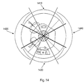
- Figure 14 illustrates one possible way of dividing the original source panorama.
- the source panorama is divided into four quadrants: an upper quadrant, a left quadrant, a right quadrant, and a lower quadrant. (The quadrants are illustrated using dotted lines.) Each quadrant becomes the source of a multicast channel. Thus, only four multicast channels are required.
- the information supplied for each quadrant should overlap the other quadrants such that only one multicast channel needs to be subscribed to.
- the overlap area will be at least as large as a client view. Referring to Figure 14, a set of overlapping quadrants are displayed: overlapping upper quadrant 1410, overlapping left quadrant 1420, overlapping lower quadrant 1430, overlapping right quadrant 1440.
- the multicasting embodiment may also include a highly compressed full panoramic image channel.
- the highly compressed full panoramic image channel would occasionally transmit a highly compressed version of the full panoramic image such that a view in any direction could be created.
- a first server could generate and serve the multicast channel carrying the overlapping upper quadrant 1410
- a second server could generate and serve the multicast channel carrying the overlapping left quadrant 1420, and so on.
- Figure 15 graphically illustrates how network bandwidth is conserved using a multicast type of system.
- a panoramic image server transmits all the tile channels on a multicast backbone.
- Various routers coupled to the multicast backbone only route multicast channels subscribed to by clients connected to their subnetworks. By routing only the multicast channels needed by clients connected to their subnetworks, the routers limit the tile information carried by the subnetworks.
- This aspect of the invention addresses one difficulty related to techniques for panning a view over a motion panorama.
- a tradeoff occurs between limiting the maximum allowable pan rate and the amount of data that is kept to render the view when shifted by the pan operation. If unlimited bandwidth is available, the entire panorama could be delivered to the client computer for every frame in the motion panorama, there would be no need to limit the pan rate, and the view would always be presented at the desired quality.
- the amount of bandwidth consumed to send such a panorama over an unlimited bandwidth link is a function of the resolution of the panorama, the size of the panorama and the frame rate for updating the panorama.
- the link has limited bandwidth (such that the entire panorama cannot be sent at the desired resolution, size and frame rate because of the limited bandwidth)
- techniques can be used to allocate the available bandwidth to provide a quality view into the panorama, while still making lower-quality portions of the panorama available if required for a pan operation.
- This approach can result in significant temporal and edge distortion when the viewpoint is panned into the lower-quality portion of the received panorama. Some of these distortions occur when the view is being generated using data from different quality tiles and can result in temporal tearing and other presentation artifacts.
- a preferred embodiment allocates the available bandwidth such that the available tile quality is a function of the distance the tile is from the current viewpoint.
- the tile quality is determined by the amount of compression (or other characteristics of the tiles) applied to each tile. Thus, tiles that are adjacent to the viewpoint and used to render the view are less compressed to create a high-quality presentation of the view. Other tiles will be more highly compressed (thus, only able to present a lower quality view) responsive to the distance the tile is from the viewpoint.
- Each "tier” consists of tiles that have a particular quality.
- the quality is determined by characteristics such as the resolution of the portion of the image represented by the data in the tiles of the tier, the frame rate for sending the data defined by a tile, the amount of compression applied to the data in the tile, and the amount of the color information maintained in the tile's data, along with other characteristics.
- a tier set is a collection of tiers that are encoded so as to balance the quality of the presentation of the tiles within the tier set with the bandwidth required to send the tile data. The creation and use of "tiers" is subsequently described.
- Figure 16A illustrates a computer system 1600 that includes a network 1601 used by at least one client computer, such as a first client computer 1603 and an n th client computer 1605, to communicate with a server computer 1607.
- the server computer 1607 receives information from an encoder array 1609 over a high-speed link.
- the encoder array 1609 receives a motion panorama image input 1611 and compresses the motion panorama image input 1611 into a number of tiered tiles of differing quality as is subsequently described.
- the high-speed link can be a network connection, an internal computer bus, or any technology for rapidly transferring data from the encoder array 1609 to the server computer 1607.
- the computer system 1600 can also include a media reader 1613 that can access tiles that are already encoded, tiered and tiled and that are resident on computer readable media such as a DVD media 1615 or other suitable media.
- the operation of the computer system 1600 is that the motion panorama image input 1611 is provided to the encoder array 1609 on a frame-by-frame basis.
- the encoder array 1609 compresses the motion panorama image input 1611 to generate the tier and tile structure subsequently described and sends this information to the server computer 1607.
- the server computer 1607 receives subscriptions to the differing quality tiles from the first client computer 1603 and/or the n th client computer 1605. The tile subscriptions need not be the same for each of the clients.
- the server computer 1607 distributes the subscribed-to tiles to the clients over the network 1601.
- the server computer 1607 can also access prerecorded tiers and tiles using the media reader 1613 to read a computer readable media such as the DVD media 1615.
- Figure 16B illustrates a DVD media creation system 1620 that receives a motion panorama image input 1621 at an encoder array 1623 to generate the tiered and tiled information that is transferred to a DVD drive 1625 configured to write the tiered and tiled information onto a DVD media 1627.
- a DVD media creation system 1620 that receives a motion panorama image input 1621 at an encoder array 1623 to generate the tiered and tiled information that is transferred to a DVD drive 1625 configured to write the tiered and tiled information onto a DVD media 1627.
- suitable media and media drivers can be used other than the DVD drive 1625 and the DVD media 1627.
- Figure 16C illustrates an apparatus 1630 that can read tiered and tiled information from a DVD media 1631 using a DVD drive 1633 under control of a computer system 1635.
- the computer system 1635 can present the accessed information as is subsequently described.
- other suitable media and media drivers can be used.
- FIG. 17 illustrates a computer system, indicated by general reference character 1700, that incorporates the invention.
- the computer system 1700 includes a processor 1701 that includes a central processor unit (CPU) 1703, a memory section 1705 and an input/output (I/O) section 1707.
- the I/O section 1707 is connected to a user interface 1711, a disk storage unit 1713 and a DVD/CD-ROM drive unit 1715.
- the DVD/CD-ROM drive unit 1715 can read a CD-ROM medium 1717 that typically contains a program and data 1719.
- the DVD/CD-ROM drive unit 1715 (along with the CD-ROM medium 1717 ) and the disk storage unit 1713 comprise a file storage mechanism.
- Some embodiments of the invention include a network interface 1721 that connects the computer system 1700 to a network 1723. Portions of the program and data 1719 can be resident in a program memory 1725 for execution by the CPU 1703.
- a DVD medium 1727 contains tired and tiled motion image data 1729 that can be read by the DVD/CD-ROM drive unit 1715 for presentation by the user interface 1711, other presentation device, or a display device.
- a client computer 1731 can also access tier and tile information through the network 1723.
- motion images can be collected by a video camera 1733 and processed by a video encoder array 1735 to directly create the tier and tile information in real time.
- a video encoder array 1735 to directly create the tier and tile information in real time.
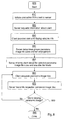
- Figure 18 illustrates a presentation process 1800 that can be used by a computer to present a view into a panorama.
- the presentation process 1800 initiates at a 'start' terminal 1801 and continues to a 'negotiate communication' procedure 1803.
- the 'negotiate communication' procedure 1803 communicates with the source of the panoramic image to determine the bandwidth available for transferring data representing the panorama to the computer. In one preferred embodiment this process determines the expected bandwidth between a networked panoramic image source and a client computer executing the presentation process 1800.
- the 'negotiate communication' procedure 1803 determines the available bandwidth (communication speed) between a device (such as the DVD/CD-ROM drive unit 1715 or the media reader 1613 ), used to access media containing the panoramic image, and the computer executing the 'negotiate communication' procedure 1803.
- a 'receive availability information' procedure 1805 obtains availability information from the panorama source that represents the available tiers and tiles that can be provided by the panorama source.
- a 'subscribe to tiles' procedure 1807 uses the availability information, the viewpoint into the panoramic image, and the bandwidth (as found by the 'negotiate communication' procedure 1803 ) to determine a tile subscription for the computer.
- the 'subscribe to tiles' procedure 1807 can also specify that not all frames are to be sent for a subscribed-to tile (thus, skipping frames for that tile).
- a 'receive tiered tiles' procedure 1809 receives the data from the subscribed-to tiles. This data is used to present a view into the panorama by a 'present view' procedure 1811.
- the presentation process 1800 continues to a 'pan operation' decision procedure 1813 that detects whether the viewpoint into the panorama has changed (for example, by a "pan” operation) or whether the viewpoint has remained substantially constant for a period of time (thus implying that the user is interested in the presented view and is relatively less likely to pan beyond the corresponding tile(s) representing the current view).
- the presentation process 1800 continues to an 'adjust subscription for quality' decision procedure 1815 that can adjust the tile subscription to increase (or reduce) the quality of the presented view.
- An increase in quality can be accomplished by selecting a less compressed tile, by increasing the frame rate of the tile, by increasing the amount of color information provided with the original data (the color depth), by increasing the presented resolution, by increasing the size of the view, by adjusting the field of view, and/or by other mechanisms well understood by one skilled in the art.
- the 'adjust subscription for quality' decision procedure 1815 determines that the quality need not be adjusted, the presentation process 1800 continues to the 'receive tiered tiles' procedure 1809. However, if the quality is to be adjusted, the presentation process 1800 continues to the 'subscribe to tiles' procedure 1807 that adjusts the tile subscription accordingly.
- the presentation process 1800 continues to a 'present new view' procedure 1817.
- the 'present new view' procedure 1817 presents a new view based on the new viewpoint and possibly using reduced-quality tiles.
- the presentation process 1800 then continues to a 'significant pan operation' decision procedure 1819 that determines whether the viewpoint change caused the view to be presented using data from reduced-quality tiles (or is likely to do so in the near future). If so, the pan operation was a "significant pan operation" and requires a change to the tile subscription so as to receive high-quality tiles containing data for the presented view. In this instance, the presentation process 1800 continues to the 'subscribe to tiles' procedure 1807 to make this change.
- the presentation process 1800 continues to the 'receive tiered tiles' procedure 1809 to receive the data from the subscribed-to tiles for the next frame.
- the 'significant pan operation' decision procedure 1819 can be implemented in various ways.
- the 'significant pan operation' decision procedure 1819 monitors whether the pan operation has moved the viewpoint such that the generation of the view uses data from a tile belonging to a lower-quality tier.
- Another preferred embodiment uses a predictor to predict that the viewpoint will soon require a tile belonging to a lower-quality tier to generate the view and thus, subscribe to higher-quality tiles for the expected view.
- Other prediction techniques known in the art can be used.
- the 'adjust subscription for quality' decision procedure 1815 monitors changes in the viewpoint. If the viewpoint remains in a high-quality tier for a sufficient period (that is, when the viewpoint becomes stable), the 'adjust subscription for quality' decision procedure 1815 can change the tile subscription to optimize the bandwidth use to increase the quality of the presented view. Examples of this would be to subscribe to tiles that have a higher frame rate or to subscribe to tiles that are less compressed.
- the presentation process 1800 can also detect when the viewpoint is likely to move out of the area of the panorama that has high-quality tiles and thus likely to require the view to be generated from data in a tile belonging to a lower-quality tier.
- the viewpoint stability can be determined by monitoring the viewpoint's history, predicting that the viewpoint into the panorama will change and that this change would cause the view to be generated using lower-quality tiles.
- the stability can be determined by monitoring how much the viewpoint has changed over a period of time. Other techniques well known in the art can also be used.
- the 'present new view' procedure 1817 uses data from existing tiles to generate the new view after the viewpoint has changed. If the viewpoint has changed such that tiles from lower-quality tiers are needed to generate the view, the 'present new view' procedure 1817 presents the view from this data. This results in a lower-quality presentation until the newly subscribed-to tiles belonging to a high-quality tier are received at the 'receive tiered tiles' procedure 1809. Although the view is always presented, the quality of the presentation may be temporarily reduced and may include temporal and/or spatial tearing or other quality artifacts.
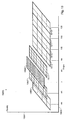
- FIG 19 illustrates an example tile subscription 1900 having a quality axis 1901 and a tile angle axis 1903.
- Tier-3 tiles 1905, 1913, 1915, 1917, 1919 are the tiles that have the least quality data as indicated by the wide hashing in these tiles.
- Tier-2 tiles 1907, 1911 have better quality than the tier-3 tiles 1905, 1913, 1915, 1917, 1919 but less quality than a tier-1 tile 1909.
- each of the tiles 1905, 1907, 1909, 1911, 1913, 1915, 1917, 1919 subtends 45 degrees of the panorama.
- a 360-degree panorama is represented by the data in the eight tiles 1905, 1907, 1909, 1911, 1913, 1915, 1917, 1919.
- the tier-1 tile 1909 includes the highest quality data such that presentation of the view from the tier-1 tile 1909 provides the best quality. If presentation of the view requires data from the other tiles, the viewer of the presentation will possibly notice temporal and/or spatial tearing.
- multiple tiles can be within each tier; that different angular widths can be used with each tile, and that the subscribed tiles can be distributed as has been previously described.
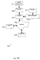
- FIG 20A illustrates a server process 2000 that can be used by the server computer 1607 to distribute tiles to one or more clients (for example, the n th client computer 1605 ) .
- the server process 2000 initiates at the 'start' terminal 2001 and continues to a 'connect with client' procedure 2003 that recognizes when a client computer requests a connection with the server computer 1607 and performs the functions required to satisfy this request.
- the server process 2000 continues to a 'negotiate communication' procedure 2005.
- the 'negotiate communication' procedure 2005 is the server side of the communication negotiation of the 'negotiate communication' procedure 1803 performed by the client and previously discussed with respect to Figure 18.
- a 'send availability information' procedure 2007 sends availability information to the client computer.
- the availability information includes the characteristics and quality of the available tiers and the available tiles within the tiers.
- the client uses this information during the 'subscribe to tiles' procedure 1807 previously described.
- a 'receive encodings for frame' procedure 2009 receives a tiered and tiled frame of data from the encoder array 1609 or by reading the DVD media 1615 . This procedure continues for so long as frames are available from the panorama source or until otherwise terminated.
- the 'receive encodings for frame' procedure 2009 provides a 'frame received' signal 2010 to indicate when the received tiles can be sent to a client.
- a 'receive tile subscription' procedure 2011 receives the tile subscription from the client computer.
- the tile subscription for each client is used to determine which tiles that are received from the encoder array 1609 are to be sent to each client.
- the tile subscription is used to select which tiles are to be broadcast on the multicast channels.
- a 'send tiles' procedure 2013 sends the subscribed-to-tiles to the clients that have subscribed to them. The subscribed-to-tiles are sent responsive to the 'frame received' signal 2010 .
- tiles containing portions of that data are sent to the client computers according to the tile subscription information provided by the client.
- a 'subscription changed' decision procedure 2015 detects whether a client has changed the tile subscription. If the tile subscription for a particular client (or multicast channel) has not changed, the server process 2000 continues to the 'send tiles' procedure 2013 to send the subscribed-to-tiles for the next frame. However, if the client changed its tile subscription, the server process 2000 continues to a 'subscription terminated' decision procedure 2017 to determine if all tiles are unsubscribed. If all tiles have been unsubscribed, the server process 2000 completes through an 'end' terminal 2019. Otherwise, the server process 2000 continues to the 'receive tile subscription' procedure 2011 to update the tile subscription for the client.
- Figure 20B illustrates an encoding process 2030 for encoding creating tiled tiers of panoramic frames.
- the encoding process 2030 starts at a 'start' terminal 2031 and continues to an 'initialization' step 2033 that initializes each of the encoders in the encoder array 1609 to provide the tier and tile characteristics according to the availability information for the panorama.
- An 'iteration' step 2035 determines when all the frames from a moving panorama image have been encoded. After all the frames have been encoded the encoding process 2030 completes through the 'end' terminal 2037.
- the encoding process 2030 continues to a 'receive panorama frame data' step 2039 that receives a frame of the panoramic image from an image source such as a video camera, computer generated raster, or other image data source. Once the frame is received, the encoding process 2030 continues to an 'encode frame data' step 2041.
- the 'encode frame data' step 2041 provides processing for each tile in each tier.
- One preferred embodiment simultaneously processes each portion of the frame to generate the tiles in parallel.
- Other embodiments can assign multiple tiles to a specific encoder.
- 24 encoders are used to encode a panorama with three-tiers and eight tiles per tier.
- Other tier/tile combinations will be subsequently described with respect to Figure 22.
- the encoder array 1609 can be configured to provide different levels of quality for each encoded tile. These quality parameters include the amount of compression, the frame rate, the view size and the color depth for each pixel in the tile.
- the color depth represents the number of bits per pixel that represent the color of the pixel (including monochrome pixels and black & white pixels).
- a 'send encoded tiles' step 2043 sends the data for each tile to the server computer 1607 using a high speed communications link (for example, a computer data bus, a high-speed network link, or other high-speed communications) where it is stored in the server's memory according to the availability information by the 'receive encodings for frame' procedure 2009 of Figure 20A.
- a high speed communications link for example, a computer data bus, a high-speed network link, or other high-speed communications
- the encoder array 1609 can have its own memory for storing the tiles prior to sending the tiles to the server computer 1607.
- Figure 21 illustrates an application of an encoder array to a panorama 2100 that illustrates how an electronic panorama image 2101 (that includes a first portion 2103, a second portion 2105, a third portion 2107, and a fourth portion 2109 ) is encoded by an encoder array 2111 in one preferred embodiment.
- the electronic panorama image 2101 can be portioned in other ways than indicated. This includes ways where the portions are of differing sizes and/or where the portions overlap. In addition, the portions need not cover the entire height of the panorama but can be a single tile as has been previously discussed.
- the encoder array 2111 has three tiers and three groups: a first group of encoders 2113, a second group of encoders 2115, and a third group of encoders 2117. Other preferred embodiments organize the encoder array differently. These embodiments can include more or less encoders, more or less tiers, and/or more or less groups of tiers.
- One preferred embodiment of the encoder array consists of only the first group of encoders 2113 .
- This encoder array has a tier 1 encoder for each of portion 2103, 2105, 2107, 2109 of the electronic panorama image 2101 that encodes a high-quality version of their respective portions.
- the tier 2 encoders encode an intermediate-quality version of their respective portions.
- the tier 3 encoders encode a reduced-quality version of their respective portions.
- the first group of encoders 2113 generates tiered encodings for each of the portions of the panorama. These encodings are sent to the server for each frame of the panorama. The server then distributes the encodings to the client computers according to their respective tile subscriptions.
- Another preferred embodiment includes the second group of encoders 2115 and the third group of encoders 2117. These encoders generate tiers that have different quality characteristics from the first group of encoders 2113.
- a client computer for example, the first client computer 1603
- the client computer can receive information about each generated tile in every tier.
- the client computer can subscribe to tiles from any tier to receive data that can be used to provide the desired quality presentation while still providing responsive pan capability.
- a binary tree structure can be used to represent the tiers and tiles.
- One skilled in the art will understand that many other data structures in memory can also be used to organize the tiles.
- One preferred approach for organizing the tiers and tiles is to create a tier set that has characteristics suitable for a particular available bandwidth.
- a client can select the tier set that is optimized for the available bandwidth between the server and the client.
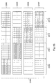
- Figure 22 illustrates an example tiling strategy 2200 using multiple groups of tiers, overlapping tiles, and different quality characteristics.
- the example tiling strategy 2200 includes a first tier set 2201, a second tier set 2203, and a third tier set 2205.
- the first tier set 2201 includes a high-quality 45-degree tier 2207, an intermediate-quality 45-degree tier 2209, and a 'reduced-quality 45-degree tier' 2211.
- the second tier set 2203 includes a 'high-quality 90-degree tier' 2213, a 'high-quality 90-degree (offset) tier' 2215, and a 'reduced-quality 90-degree tier' 2217.
- the third tier set 2205 includes a reduced-quality 180-degree tier 2219 and a reduced-quality 180-degree (offset) tier 2221.
- a first wrapped tile 2223 and a second wrapped tile 2225 are tiles that wrap around the planar representation of the panorama.
- each tier has a number of tiles.
- the amount of data that is within the tile is indicated by the height of the tile.
- the shorter the tile the more compressed (and lower quality) is the data in the tile.
- the high-quality tile 2227 has less compression with respect to intermediate-quality tiles 2229 that in turn has less compression than low-quality tiles 2231.
- the data in each tile of a tier can be refreshed at a particular frame rate.
- the frame rate can be different for each tier in the tier set (and/or different for each tile).
- each tier generally has quality characteristics that are different from every other tier. Tiles from multiple tiers (in different tier sets) can be subscribed-to as desired.
- tier sets need not be included in the tiling strategy and that a binary tree data structure or other data structures can represent a tiling strategy.
- the data in each tile indicated in the example tiling strategy 2200 is provided by a single encoder of the encoder array 1609.
- Other preferred embodiments share the encoder among multiple tiles so long as the frame rate requirements are met for encoding the tiles.
- the tiers in each set can be related to provide a unified compression/quality schema that is often optimized for a particular bandwidth.
- the tiers in the first tier set 2201 provide three levels of quality corresponding to the three tiers.
- the tiers in the second tier set 2203 consist of two high-quality tiers (the 'high-quality 90-degree tier' 2213 and the 'high-quality 90-degree (offset) tier' 2215 ) having overlapping tiles and the 'reduced-quality 90-degree tier' 2217.
- the tiles in the third tier set 2205 consist of the reduced-quality 180-degree tier 2219 and the reduced-quality 180-degree (offset) tier 2221.
- One skilled in the art will understand that here are many different possibilities for the tiling and tier strategy other than that illustrated by the example tiling strategy 2200.
- One preferred embodiment uses a binary tree structure for each tier set.
- Yet another preferred embodiment uses a plurality of tier sets similar to the first tier set 2201 but each tier set being optimized for use with a particular bandwidth.
- the client computer determines which tiles to select based on the availability information.
- the availability information specifies the available tile and tier information.
- the client computer then subscribes to the appropriate tiles responsive to the desired quality of the presentation and the available bandwidth.
- the availability information can include the tile information, the tier information, the compression information, and/or other information used to define the tiles available to the client computer.
- the client computer receives the availability information at the 'receive availability information' procedure 1805 described with respect to Figure 18. If the client computer wants the example tile subscription 1900 illustrated in Figure 19 using the availability information for the example tiling strategy 2200, the client computer would subscribe to the high-quality tile 2227 to correspond to the tier-1 tile 1909, the intermediate-quality tiles 2229 to correspond to the tier-2 tiles 1907, 1911, and the low-quality tiles 2231 to correspond to the tier-3 tiles 1905, 1913, 1915, 1917, 1919 .
- this is but one example of how the client computer would subscribe to tiles for presentation.
- Another possible subscription for example, is to subscribe to a high-quality tile 2237, low-quality tiles 2233 (or a 'low-quality tile' 2235 ) along with a 'low-quality tile' 2239.
- Yet another possible subscription is to subscribe to the high-quality tile 2237, the low-quality tiles 2233 (or the 'low-quality tile' 2235 ) and a 'high-quality tile' 2241 thus allowing for extending high-quality pan operations for pans moving past 90 degrees toward 45 degrees.
- the 'adjust subscription for quality' decision procedure 1815 can dynamically adjust the tile subscription based on the history of the viewpoint movement. For example if the viewpoint has not changed over some period of time, the 'adjust subscription for quality' decision procedure 1815 can unsubscribe from the lower-quality tiles that have not been used to present the view (thus making more bandwidth available) and can subscribe to tiles that will improve the quality of the view at the expense of the ability to smoothly pan through the panorama. If the viewpoint starts to change, the 'adjust subscription for quality' decision procedure 1815 can again subscribe to the lower-quality tiles to restore the pan capability.
- example tiling strategy 2200 can provide different quality tiles optimized for different quality characteristics and that the 'adjust subscription for quality' decision procedure 1815 can dynamically select tiles to best meet the changing needs, use, and operating constraints to present the highest possible quality view into the panorama.
- Figure 23 illustrates a distributed-quality encoding tier strategy 2300 that can be used to simplify the subscription process in the client computer.
- the distributed-quality encoding tier strategy 2300 provides another method for utilizing the available bandwidth between the server and client computers.
- the panorama is not partitioned into multiple tiles. Instead, each tile contains data for the entire panorama.
- Each tile is available for subscription by the client computer.
- Each of the tiles is encoded such that the quality of the encoded data in the tile is a function of the angular distance the encoded data is from a viewpoint.
- one tile uses a high-quality data encoding from 0 degrees to 90 degrees; a medium-quality data encoding from 90 to 180 degrees and from 0 to -90 degrees; and a low-quality data encoding from 180 to 270 degrees.
- the client selects a particular tile responsive to the client's viewport. As the viewport changes, the client subscribes to a different tile that has the high-quality data encoding at the changed viewpoint.
- Figure 23 graphically indicates the distributed-quality encoding tier strategy 2300 that (in this example) includes four different tiles of the panorama (a first tile 2301, a second tile 2303, a third tile 2305, and a fourth tile 2307). Each of these tiles contains data that represents the panorama at the same time. Each of these tiles is encoded using a distributed quality encoding such that the encoding for the tile is distributed over the tile. Thus, different portions of the tiles have its data encoded for high-, medium- and low-quality. For example, assume that the tiles are separated into four quadrants of 90 degrees (a first portion 2309, a second portion 2311, a third portion 2313 and a fourth portion 2315 ) .
- the first portion 2309 of the first tile 2301 is the high-quality encoded data (as indicated by the dense cross-hatch pattern). If the first portion 2309 represents quadrant 0-90 degrees, then the data in the adjacent quadrants (the second portion 2311 and the fourth portion 2315 ) could be encoded to medium-quality and the data in the third portion 2313 (representing the data directly behind the viewpoint) can be encoded to low-quality.
- the client receives portions of the panorama as high-quality, medium-quality and low-quality data without a need to subscribe to multiple tiles. This simplifies the subscription process within the client computer.
- Each of the other tiles has the high-quality encoded data in a different portion of the tile.
- the client computer is able to display high-quality images by selecting which tile to receive responsive to the specified viewpoint.
- each set of tiles can be optimized for use with a particular bandwidth.
- the tiles can use portions having different characteristics than those shown in Figure 23.
- the portions can extend for more or less than the 90 degrees shown; need not cover the entire vertical extent of the panorama, nor do the portions need to cover the same angular area as any other portion.
- the high-quality portions of the different data encodings of the panorama can overlap.
Abstract
Description
- The present invention relates to the field of image processing and data distribution. In particular the present invention discloses methods and apparatus for processing, transmitting, and post-processing panoramic image information.
- Most cameras only record a view within a small viewing angle. Thus, a typical conventional camera only captures an image in the direction that the camera is aimed. Such conventional cameras force viewers to look only at what the camera operator chooses to focus on.
- Panoramic cameras capture a much wider field of field. A panoramic camera constructed using an optical "fish-eye" lens may capture at most a 210-degree field of view. A panoramic camera constructed with a catadioptric lens captures a full 360-degree panoramic image. With a large panoramic field of view, individual panoramic image viewers can decide what they will focus on.
- Conventional images are often delivered by electronic means. For example, television and the Internet deliver conventional images across wired and wireless electronic media. However, there are no standard means of delivering panoramic images electronically. Since panoramic images are so large, it is difficult to deliver panoramic images using conventional image transmission techniques. To further compound the problem, motion panoramic images traditionally require a very high bandwidth channel for electronic distribution. Thus, it would be desirable to have an electronic distribution system that efficiently distributes motion panoramic image information.
- Another difficulty with motion panoramic images is that a user often desires to rapidly pan the view from one area of the panorama to another. Because of the limited bandwidth available for sending the panoramic image from a motion panoramic image server to a client system, such rapid pan operations result in significant latency delays and/or temporal tearing between the time the user performs the pan operation and the display of the resulting view. Thus, it would be desirable to utilize the available bandwidth to provide both high-quality data (for the portion of the motion panoramic image being viewed) and lower-quality data (for the portions of the motion panoramic image that are not being viewed and dependent on the likelihood of that portion being viewed).
- Yet another problem with the prior art distribution of motion panoramic images is caused by the latency between a user's command and the result of the user's command. This latency is a function of the time required to send the command to the image encoder and the time required by the encoder to propagate the response to the command back to the user. This latency can be of the order of tens of seconds. Thus, it would be advantageous to provide technology that allows the user's command to be satisfied by a server between the encoder and the client.
- Although the communication link between server computers and client computers are beginning to have more bandwidth with the use of digital subscriber lines (DSL) and ISDN, the amount of information flowing across these larger bandwidth links are more complex, are of higher resolution, and higher frame rates. Thus, bandwidth limitations occur even for these more advanced communication links. Thus, it would be advantageous to provide techniques for using the available bandwidth to present a high-quality image while at the same time maintaining sufficient information about the non-presented portions of the panorama to minimize the consequences of panning outside of the high-quality image.
- The present invention is defined in the appended claims.
- One embodiment comprises an electronic image distribution apparatus for distributing motion panoramic images. The main portion of the apparatus is a motion panoramic image server that has a source of motion panoramic images. The source of panoramic image frames can be a motion panoramic image playback device or a connection to a motion panoramic camera system. The motion panoramic image server transforms the panoramic image frames into an intermediate planar representation that is more conducive for electronic transmission. The motion panoramic image server then transmits the motion panoramic images to client systems.
- In addition, one preferred embodiment discloses methods and apparatus for obtaining portions of a panorama over a limited bandwidth link. The invention uses an encoder array to multiply encode the panorama into tiles that have different characteristics. The computer that uses the encoded data to present a view into the panorama subscribes to the tiles containing the encoded data. The tiles that are subscribed-to are selected based on the bandwidth available to transfer the tiles and the quality of the data in the tiles. The computer selects higher-quality tiles near the viewpoint and lower-quality tiles dependent on the distance the tile is from the viewpoint. As the viewpoint is altered (such as by a pan operation), the computer dynamically adjusts the tile subscription to present a quality image. If the pan operation moves the viewpoint such that data from lower-quality tiles is required to present the view, the data is presented using the lower-quality data until the higher-quality data resulting from the new tile subscription arrives. The presentation of the lower-quality data can be reduced or avoided by limiting the range of an allowable pan, by predicting a future need for high-quality tiles based on a pan history, by providing tiered tiles near the viewpoint to reduce temporal and other presentation artifacts.
- Another preferred embodiment provides an entire panorama containing distributed-quality data to the client computer. In this embodiment the panorama is encoded such that a portion of the panorama is encoded for high-quality, other portions of the panorama are encoded for reduced-quality, and yet other portions of the panorama are encoded for low-quality (one skilled in the art will understand that more than three levels of quality can be used within the panorama). Multiple encodings of the panorama differing by the placement of the relative quality portions are provided to the client. The client is thus able to select the panorama encoding that includes a high-quality portion responsive to the client's viewpoint. When the viewpoint moves away from the high-quality portion of the currently selected panorama encoding, the client subscribes to a different panorama encoding that includes a high-quality portion at responsive to the new viewpoint.
- Preferred embodiments include (without limitation) system methods, client computer side methods, server computer side methods, server apparatus, client apparatus, and computer program products for the server computer and the client computer.
- The invention will be described below with reference to exemplary embodiments and the accompanying drawings, in which:
- Figure 1
- illustrates one embodiment of a panoramic camera system that creates annular images.
- Figure 2a
- illustrates an annular image that is recorded by the panoramic camera system of Figure 1.
- Figure 2b
- illustrates how the annular image of Figure 2a appears after it has been unwrapped by geometrical transformation software.
- Figure 3
- illustrates the 360-degree band that the panoramic camera system of Figure 1 captures and Figure 3 also illustrates a cylindrical projection data format.
- Figure 4
- illustrates a networked computer systems arrangement used to distribute motion panoramic images captured by the panoramic camera system Figure 1 from a panoramic image server to client systems.
- Figure 5A
- illustrates a conceptual view of a spherical view captured by the panoramic camera system of Figure 1.
- Figure 5B
- illustrates a panoramic image frame in a spherical intermediate planar representation that has been unwrapped and divided into individual tiles.
- Figure 5C
- illustrates a panoramic image frame in a cylindrical intermediate planar representation that has been divided into individual tiles or a spherical intermediate planar representation that has been adjusted and divided into tiles.
- Figure 5D
- illustrates a panoramic image frame in a low-resolution intermediate planar representation that has been divided into individual tiles.
- Figure 5E
- illustrates a panoramic image frame in a medium resolution intermediate planar representation that has been divided into individual tiles.
- Figure 5F
- illustrates a panoramic image frame in a high-resolution intermediate planar representation that has been divided into individual tiles.
- Figure 5G
- illustrates a panoramic annular image frame that has been divided into spatially variant tiles.
- Figure 6A
- illustrates a view within a panoramic image frame in an intermediate planar representation.
- Figure 6B
- illustrates four tiles from Figure 6A transmitted to construct a view within a client system.
- Figure 7A
- illustrates a view within a panoramic image frame intermediate planar representation that has suddenly shifted by a large angular value.
- Figure 7B
- illustrates a view within a panoramic image frame intermediate planar representation that has suddenly shifted by a small angular value.
- Figure 8
- illustrates a flow diagram that describes how a panoramic image client system negotiates a connection with a motion panoramic image server.
- Figure 9
- illustrates a flow diagram that describes how a motion panoramic image server sends image tiles to a panoramic image client.
- Figure 10
- illustrates a flow diagram that describes how a motion panoramic image client renders a panoramic image view using image tiles received from a server.
- Figure 11
- illustrates a panoramic image frame in an intermediate planar representation that has been divided into overlapping tiles.
- Figure 12
- illustrates a networked computer arrangement wherein a panoramic image server distributes motion panoramic image tiles on individual multicast channels.
- Figure 13
- illustrates a flow diagram that describes how a motion panoramic image client subscribes to multicast panoramic image tile channels and renders an image using received image tiles.
- Figure 14
- illustrates a panoramic annular image divided into quadrants that are served on different multicast channels.
- Figure 15
- illustrates a panoramic image server that transmits panoramic image information on different multicast channels on a multicast backbone, and client systems that subscribe to the multicast channels.
- Figure 16A
- illustrates an overview of the architecture of one preferred embodiment.
- Figure 16B
- illustrates an apparatus to store a motion panorama image on a computer readable media according to a preferred embodiment.
- Figure 16C
- illustrates an apparatus to read a motion panorama image from a computer readable media according to a preferred embodiment.
- Figure 17
- illustrates a computer system capable of using the invention in accordance with a preferred embodiment.
- Figure 18
- illustrates a process of presenting a view into a panoramic source in accordance with a preferred embodiment.
- Figure 19
- illustrates a conceptual example of tiered data used to present a panoramic image in accordance with a preferred embodiment.
- Figure 20A
- illustrates a process of sending tiles from a server in accordance with a preferred embodiment.
- Figure 20B
- illustrates a process of encoding tiles from a frame in accordance with a preferred embodiment.
- Figure 21
- illustrates application of an encoder array to a panorama in accordance with a preferred embodiment.
- Figure 22
- graphical representation of one example tiling strategy that can be used with a preferred embodiment.
- Figure 23
- graphical representation of a variable-quality encoding tier strategy that can be used with a preferred embodiment.
- A method and apparatus for compressing and distributing motion panoramic images is disclosed. In the following description, for purposes of explanation, specific nomenclature is set forth to provide a thorough understanding of the present invention. However, it will be apparent to one skilled in the art that these specific details are not required in order to practice the present invention. For example, the present invention's method of distributing panoramic images has been described with reference to the Internet. However, other types of digital information distribution systems (for example private data networks and satellite systems) may be used with the teachings of the present invention.
- Figure 1 illustrates an embodiment of one possible 360-degree panoramic camera system. The
image capture mechanism 150 of the panoramic camera system captures an angular image of the surrounding panorama that is reflected off themain reflector 110. More details about the panoramic camera system of Figure 1 can be found in the copending patent application entitled "Panoramic Camera", filed June 11, 1997, having serial number 08/872,525. - Figure 2a illustrates an example of a panoramic image captured as an annular image. As illustrated in Figure 2a, the surrounding panorama is distorted by the main reflector having radial symmetry such that the surrounding represented as a two-dimensional annular image. In one embodiment, the shape of the main reflector transforms the standard rectangular coordinate system of the image into a polar coordinate system. To view the panoramic image captured as a two-dimensional annular image, the annular image may be unwrapped to create an intermediate planar representation. The unwrapping is performed using a geometric transformation operation. Figure 2b illustrates how the annular image of Figure 2a appears after the images are geometrically transformed from the annular representation to a rectangular intermediate planar representation.
- The panoramic camera system of Figure 1 captures an entire 360-degree image of the surrounding horizon as illustrated in Figure 3. The panoramic camera system captures a panoramic image that includes objects as low as 50 degrees below the horizon and objects as high as 50 degrees above the horizon. However, alternate panoramic camera systems may capture a full spherical panoramic view, a partial 180-degree hemispherical view, or any other panoramic view. Furthermore, a panoramic image may be constructed by combining a mosaic of conventional images captured with conventional camera systems. For example, eight conventional cameras can be used to capture images from eight different directions. Those images are then combined together to create a single panoramic image.
- When the
image capture mechanism 150 of the panoramic camera of Figure 1 is a motion image capture mechanism such as a charged coupled device (CCD) or a film-based motion picture image capture system, then it is possible to capture a series of panoramic annular images. The series of panoramic annular images can be used to generate a motion panoramic display. Figure 4 illustrates one possible embodiment of an electronic motion panoramic image capture system. - Referring to Figure 4, a
panoramic camera system 405 captures a series of panoramic annular image frames with an electronic image capture mechanism. For example, the electronic image capture mechanism can be a charged coupled device image capture mechanism or CMOS image sensor that generates digitized panoramic annular image frames. The panoramic annular image frames are transmitted frompanoramic camera system 405 to apanoramic image server 400 across a highbandwidth communication link 402. The communication link must be high bandwidth since each panoramic annular image frame contains a very large amount of information and, to provide a flicker-free motion image, several panoramic images must be transmitted each second. - Alternate embodiments of motion panoramic image capture systems can also be used. For example, a motion panoramic capture system may be created with two motion picture camera systems pointing in opposite directions wherein each motion picture camera system is equipped with a fisheye lens that captures at least a 180 degree hemispherical field of view. In such a panoramic image system, two distorted fisheye images from each hemispherical view would need to be "stitched" together to create a single panoramic image.
- As previously set forth, the full panoramic annular image frames generated by the panoramic camera system (such as
panoramic camera system 405 of Figure 4) are so large that a very high bandwidth link is needed to transmit full motion images to a recipient. Such high bandwidth links are rare and expensive. Thus, for mass distribution of panoramic imagery, more bandwidth efficient methods of distributing panoramic images are needed. - The present invention introduces two different methods of distributing motion panoramic images. A first method divides panoramic images into tiles and transmits only the tiles needed to construct a desired image. A second method, described in a later section, divides panoramic images into individual tiles and then transmits all the tiles on different multicast channels.
- To efficiently transmit a panoramic image, the present invention first proposes a selective tile transmission system. In the selective tile transmission system, a server computer system divides each panoramic frame into tiles. The tile size and shape are preferably selected in such a manner that is dependent upon a coordinate system used by the format used to transmit the tiles. Then, the tiles needed to construct an image on a client computer system are transmitted from the server system to individual clients.
- In a preferred embodiment, the server system transforms each incoming panoramic image frame into an intermediate planar representation. This transformation step is not necessary but provides certain advantages. The selective tile transmission system will be described with reference to a system that performs this transformation in Figures 4, 5, 6, 7, 8 and 9.
- Referring to the particular embodiment of the selective transmission system illustrated in Figure 4, a panoramic annular
image transformation system 417 "unwraps" annular panoramic image frames into an intermediate planar representation. The intermediate planar representation is more convenient for generating images suitable for viewing. Specifically, the intermediate format should require fewer calculations to generate a final rectangular projection. - In one embodiment, the incoming annular panoramic image data is geometrically transformed into a spherical coordinate system with a spherical projection representation. In such an embodiment, a single frame of the image data may be viewed with the Live Picture viewer from Live Picture, Inc. Figure 5A conceptually illustrates a spherical data format wherein the view of the surroundings is projected onto a sphere surrounding a viewpoint.
- In another embodiment, the incoming annular panoramic image data is geometrically transformed into a cylindrical coordinate system in a cylindrical projection representation. An image transformed into a cylindrical coordinate system may be viewed with the QuickTime VR viewer created by Apple Computer, Inc. Figure 3 conceptually illustrates a cylindrical data format wherein the view of the surroundings is projected onto a cylinder surrounding a viewpoint.
- After converting the panoramic image frames into an intermediate planar representation, the system of the present invention divides the intermediate planar representation into individual tiles. In the present invention, the size of the tiles are dependent upon the coordinate system of the intermediate planar representation. In such embodiments, the tiles may be spatially variant.
- The size of the tiles may further be dependent upon the client system that will be displaying the panoramic image data. In such an embodiment, each client uses a different process (441 or 445) to divide intermediate planar representations into tiles since each client may use different client sizes. However, in a standardized embodiment, the size of the tiles are fixed such that a single process (illustrated as dotted box 449) may be used to divide an intermediate planar representation into individual tiles.
- Figure 5A illustrates a conceptual diagram of the spherically encoded intermediate planar representation. As illustrated in Figure 5A, the spherically encoded intermediate planar representation represents the surrounding world as image data mapped onto a sphere. To divide and organize the data, the sphere is broken into individual bands on sphere A, B, C, D, E, and F. Note that the bands near the "equator" of the spherically encoded intermediate planar representation contain more data than the bands closer to the "poles."
- In one embodiment of the present invention, the image data is represented by individual bands that are divided into individual tiles as illustrated in Figure 5B. Note that there will be fewer tiles in the bands from higher inclination angles. Alternatively, there will be the same number of tiles, but the tiles will contain data from smaller yaw angles. If the data from the smaller yaw angles is increased, this type of intermediate data format can be graphically illustrated as shown in Figure 5C. Note that the graphical data representation of Figure 5C also matches the cylindrical data format of Figure 3. Although the data format of Figure 5B may be used and provides certain advantages (such as a more compact data format) this document will focus on the format of Figure 5C to simplify the description.
- Referring to the particular embodiment of Figures 5A, 5B, and 5C, a first row of tiles covers from the horizon line to thirty degrees above the horizon. A second row of tiles covers from thirty degrees above the horizon to forty-two degrees above the horizon. A third, top, row of tiles covers the band from forty-two degrees above the horizon to fifty degrees above the horizon. The same angular divisions are used to divide the space below the horizon. The row size divisions are nonlinear and widest at the horizon since users are usually most interested in views near the horizon. However, different angular divisions, such as linear angular divisions, may also be used.
- After dividing each unwrapped panoramic image into tiles, a tile fetching program (440 and 443) fetches tiles for transmission to the client system. Ideally, the tile-fetching program only selects the tiles needed to create a view on a client computer system. In a preferred embodiment, the client computer system determines which tiles are needed and sends a request that specifies these tiles. The fetched tiles are transmitted using a tile-streaming program (460 and 463). By transmitting only the tiles needed to create a view on the client computer system, the system of the present invention limits the amount of information that must be transmitted from a panoramic image source server to a panoramic image client display.
- To accommodate several different magnification levels, several different sets of tile resolution may be created. For example, a low resolution "zoomed back" initial set of tiles may be used for panning around a panoramic image. The low-resolution initial tiles would encompass a large angular view. When an interesting area of the panoramic image is selected, a higher resolution set of tiles could then be selected.
- Figures 5D, 5E and 5F illustrate one possible embodiment where a panoramic image space has been divided into three tiers of magnification. An initial "zoomed back" tile magnification intermediate planar representation is presented in Figure 5D. The lower resolution intermediate planar representation of Figure 5D is used first. When a user wishes to see a portion of a view in greater detail, the client software "zooms in" by fetching tiles from the next higher resolution intermediate planar representation displayed in Figure 5E. If even greater resolution is needed, the client software "zooms in" further by fetching tiles from Figure 5F. In one embodiment, the pixel resolution of the individual tiles of Figures 5D, 5E and 5F is the same such that the individual tiles take up the same amount of screen space but provide successively greater resolution.
- As stated in the beginning of this section, the initial panoramic image frames need not be transformed into an intermediate planar representation before division into individual tiles. The intermediate planar representation transformation is usually performed since the transformation is used to put the image into a format that can be used to quickly generate an image for display with minimal processing. However, the raw panoramic image frames may immediately be divided into tiles and transmitted.
- For example, Figure 5G illustrates a raw panoramic annular image frame from the panoramic camera system of Figure 1. Before transmitting, the raw panoramic annular image is divided into tiles. In the embodiment of Figure 5G, the raw panoramic annular image is divided into square tiles that are small near the center since a small tile covers a wide image area in the annular format.
- The middle part of the annular disk is divided into larger tiles. The outside of the annular disk is divided into smaller tiles since a narrow strip of tiles is needed when constructing a view that uses information from the edge of the annular disk. Thus, the tiles are spatially variant.
- Figure 6A illustrates an example of a client system view into a panoramic image. Specifically,
client view 630 represents a view into an unwrappedpanoramic image 610 requested by a client computer system. The view is distorted since the view is illustrated within the spherical coordinate space. To construct theview 630 at a client system, a server (such as server 400) transmitstiles tile tiles client view 630 on a client computer system. (The fourtiles - Referring back to Figure 6A, if a user moves the
view 630 further to the right, then the view will cease to needtiles tiles tiles tiles client view 630 progresses even further to the right,tiles - In a preferred embodiment, the client computer system is responsible for determining when the out of view tiles are needed and when they should be transmitted. The client system makes this determination by examining factors such as how fast the user is moving the view, the latency of the connection with the server, and the parameters that define the view. The client computer system transmits a list of desired tiles to the server wherein the list of desired tiles defines which tiles should be transmitted by the server to the client computer system.
- The movement anticipation procedure described in the previous two paragraphs works well for small incremental client view shifts (which most view changes comprise). However, if a user makes a sudden quick view change, the needed tiles will not be available. For example, referring to Figure 7A, a user may quickly shift a view from a
first view position 730 to asecond view position 740. Thefirst view position 730 was being rendered withtiles second view position 740 requirestiles - To handle such sudden view changes, the present invention occasionally transmits a highly compressed version of the full panoramic image intermediate planar representation. The highly compressed panoramic image intermediate planar representation is only transmitted once every 30 or so normal frames. When a fast movement occurs, the client renders a view from the most recently received highly compressed panoramic image intermediate planar representation. This newly rendered view will not be in the normal resolution since it is being rendered from the highly compressed panoramic image intermediate planar representation. Simultaneously, the server will begin transmitting the tiles needed at the new view location.
- In the example of Figure 7A, the server will begin transmitting
tiles tiles tiles - A sudden movement may not move the view completely away from the currently available tiles. For example, a movement may place the view partially on tiles that are available and partially on tiles that are not available. In such a situation, the portion of the view that is located on available tiles can be rendered at the resolution of those tiles and the remainder of the view will be rendered using the highly compressed version. Similarly, if the user is "zoomed in" on high resolution tiles and the user moves quickly away from the currently available high resolution tiles, the view may be constructed using the tile from the next lower resolution tier if that tile is still available.
- Figures 8 and 9 provide detailed flow diagrams that fully describe how the electronic image distribution system of Figure 4 operates. Figure 8 illustrates a flowchart describing one embodiment wherein a panoramic motion image server system and a client system negotiate a connection. However, it should be noted that in other embodiments, a standard connection can be used such that there is no negotiation of connection parameters. Figure 9 describes how a server system transmits image tiles to a client system.
- Figure 4 illustrates one embodiment of a motion panoramic image client-server system wherein the bandwidth is conserved by dividing panoramic images into tiles. It should be noted that there is often not a "standard" server and client environment. Specifically, the clients, the server, and the network in a client-server environment may all vary depending on the circumstances. The capabilities of each different panoramic server system and each different panoramic client system would vary depending upon the system's specifications including the computer make, the processor type, the processor generation, the amount of random access memory available, the bus speed, and the operating system.
- To most efficiently distribute motion panoramic images from a motion panoramic image server to clients, the present invention conducts a client-server negotiation. The server system determines the characteristics of the client before determining how the client-server system will operate. Figure 8 illustrates a flow diagram describing the method of negotiating the client-server motion panoramic image connection.
- Referring to Figure 8, a client initiates a connection to a panoramic image server at
step 810. Next atstep 820, the panoramic image server requests information that describes the display characteristics of the client. Specifically, the server may request the client's frame buffer size, the client's frame buffer color characteristics, the size of the panoramic image view window, and other information relevant to the display of images on the client system. The motion panoramic image server may also request information describing the processing abilities of the client. For example, the panoramic image server may request the processor type, the processor speed, and the amount of main memory available. The client responds to the server's by sending this information to the motion panoramic image server atstep 830. - At
step 840, the motion panoramic image server uses the collected information to determine how the server will serve the client. One specific parameter that the server must decide is how to divide the unwrapped panoramic intermediate planar representation into tiles. Specifically, the size of the individual tiles will be determined. The motion panoramic image server may also determine the video frame-rate, a type of compression to use, and a processing-task division based upon the network connection speed and quality, the capabilities of the client system, and the current and anticipated processing load of the image server. - After determining the parameters of the motion panoramic image connection, the motion panoramic image server transmits the connection parameters to the client system at
step 850. The client system will use the parameters to determine how the client system will display motion panoramic images. - After the client and server have negotiated the motion panoramic image connection, the client begins requesting motion panoramic image information from the server system at
step 860. In response to the requests, the server begins transmitting motion panoramic image tiles to the client system atstep 870. Since the connection to each client is uniquely calibrated, the server will transmit panoramic image information to each different client in a manner that is specific to that particular client. The server will continue transmitting motion panoramic images until the client requests the server to stop sending images atstep 880. - Figure 9 describes how the motion panoramic image server transmits the information needed to construct a view within a motion panoramic image on a client system. Thus, Figure 9 describes in detail what occurs during the
steps - Referring to step 910 of Figure 9, the first step that the motion panoramic image server must perform is transforming a panoramic image frame into one or more intermediate planar representations. The exact method of transforming a panoramic image frame is dependent on the type of camera system used. For example, a system built using the panoramic camera system of Figure 1 would perform a geometric transformation to transform the annular panoramic image frame into the selected intermediate planar representation. If a fisheye lens panoramic camera system were used, a different geometric transformation would transform the distorted fisheye image into the desired intermediate planar representation. All subsequent actions are performed on the transformed intermediate planar representation.
- In an embodiment with magnification, the source panoramic image data is transformed into more than one intermediate planar representation of different resolutions. For example, the source panoramic image data can be transformed into low, medium, and high-resolution intermediate planar representations as illustrated in Figures 5D, 5E and 5F.
- After the panoramic image frame has been transformed into an intermediate planar representation, the method proceeds to step 920. At
step 920, the method determines if a highly compressed version of the full panoramic image frame should be transmitted. As previously set forth, a highly compressed version of the full panoramic image frame is transmitted occasionally to handle sudden movements of the client's view. In one embodiment, the motion panoramic image server transmits a highly compressed version of the full panoramic image frame during first and every Nth subsequent frame. Thus, during the first and every Nth subsequent frame, the method proceeds to step 970 where the full panoramic image frame is compressed. Then, atstep 980, the motion panoramic image server begins transmitting the highly compressed version of the full panoramic image frame. The transmission of the highly compressed version of the full panoramic image frame may occur all at once. Alternatively, the highly compressed version of the full panoramic image frame may be transmitted concurrently along with individual image tiles such that individual image tiles are not delayed. - Next, at
step 930, the one or more intermediate planar representation frames are divided into individual tiles as illustrated in Figures 5D, 5E and 5F. The size of the individual tiles is the size that was negotiated during the connection process described in the flow diagram of Figure 8. - After the frame has been divided into individual tiles, the server then fetches and transmits the tiles needed to create the client's view at
step 940. Each tile is compressed before transmission to conserve bandwidth and decrease latency. The client will use the transmitted tiles to construct an image. - At
step 950, the server method determines if the client system is done viewing the motion panoramic image. If the client is not done, the method proceeds back tostep 960. - Figure 10 illustrates a flow diagram describing a method that a client system may follow to receive information and render an image. It should be noted that Figure 10 only illustrates one possible embodiment of a client system and that significant variations can be created. For example, several of the steps described in Figure 10 such as receiving tiles and rendering an image may be performed concurrently. Alternatively, less processing could be performed in the client system and more processing could be performed in the server.
- Referring to step 1010 of Figure 10, the client receives any and all requested panoramic image tiles and highly compressed full panoramic images transmitted by the server. At
step 1020, the client attempts to render an image for the current view position. Ideally, the view will be rendered with the tiles needed for the view. However, if the client does not have the desired tiles, then the client renders an image of the current view using the available tiles for the view, tiles from lower resolution tiers, and the most recently received version of the highly compressed full panoramic image. - After rendering an image frame, the client system accepts input from a user at
step 1030. The client system may accept input, such as directional commands from a computer mouse, that pans the view within the panoramic image. The client may also accept commands that zoom-in and change the vertical viewing angle. - The client system then processes the user input to the server system at
step 1030 to determine a next view position. Atstep 1040, the client system determines if the input specifies that the user is done viewing the panoramic image information. The client panoramic image-rendering program will terminate when the user no longer wishes to view the panoramic image. - At
step 1050, the client system determines the frame tiles that are needed to create the new view position. The client system also determines if it should request tiles that are just out of the current view but are likely to be needed in the future. Specifically, the client determines if the current view is near the edge of a tile. If the client's view is near the edge of a tile, then the client will request tiles that are just outside of the client's current view. The tiles just out of view are requested such that if the client moves the view beyond the edge of the tile, then the client will be able to create a view without having to request and wait for the server to then send the needed tile. Thus, the client anticipates small view movements and is prepared to generate a view. However, if the user makes a sudden large view change, then the client rendering engine can always fall back to the highly compressed version of the full panoramic image. - Furthermore, at
step 1050, the client system determines if any currently requested tiles are no longer needed. Tiles that are no longer needed consume valuable bandwidth such that the client system should unsubscribe from tiles that are no longer needed. - After determining the tiles needed for the current view, the client system determines at
step 1060 if the needed tiles have already been requested and if there are no unnecessary tiles on request. If the needed tiles have already been requested and there are no unnecessary tiles on request, then the client system does not need to change the tile subscriptions. However, if new tiles are needed or currently subscribed tiles are no longer needed, then the client system sends a request to the server atstep 1070 that changes the tile subscription. - At
step 1080, the client system determines if any new frame tiles or compressed panoramic image frames have been received. If new frames have been received, then the method proceeds back to step 1010 to accept the new frames. Otherwise, the method proceeds back to step 1020 to render a new view image using the currently available tiles and the highly compressed full panorama image information. A different image may be generated from the same frame information if the user has shifted the view. - In one proposed embodiment, the panoramic image intermediate planar representation is divided into overlapping tiles. An example of this is provided in Figure 11. By dividing the intermediate planar representation into overlapping tiles, a degree of hysteresis is provided such that small back and forth view changes will not cause the client system to oscillate requests for new tiles.
- The selective tile transmission system described in the previous section provides a useful method of delivering motion panoramic image information in a unicast environment where each client receives a unique individual data stream. However, since the motion panoramic server must send out a unique data stream to each client, there will be a significant amount of redundant information being transmitted. To reduce the amount of redundant information being transmitted, the present invention also introduces a second multicast motion panoramic image serving system.
- Figure 12 illustrates a multicast motion panoramic image serving system constructed according to the teachings of the present invention. In the system of Figure 12, a motion
panoramic camera system 1205 delivers a series of high-resolution panoramic images across ahigh bandwidth link 1202 to a motionpanoramic server 1200. APanoramic Camera Interface 1210 handles the communication with the motionpanoramic camera system 1205. Atransformation unit 1217 transforms the raw panoramic image frames into an intermediate planar representation. As previously set forth, two possible intermediate planar representations are cylindrically encoded intermediate planar representation and spherically encoded intermediate planar representation. - After a panoramic image frame has been transformed into an intermediate planar representation, the intermediate planar representation is divided into individual tiles by
unit 1241. After dividing the intermediate planar representation into individual tiles, a set oftile streaming units multicast channels 1293 on ahigh bandwidth network 1290. Specifically, each tile position is assigned its own multicast channel. - To display a view within a motion panoramic image, each client system subscribes to the multicast channels that carry the tiles needed to construct the desired view. For example,
client system 1295 needs the two tiles delivered bytile streaming units client system 1295 subscribes to the multicast channels transmitted by those tile streaming units. - Figure 13 provides a flow diagram that describes one possible method that a client system may follow to render a view from a motion panoramic server constructed according to the teachings of Figure 12. Initially, at
step 1310, the client system subscribes to the multicast panoramic tile channels necessary to render a view from an initial view location. Routers and switches that couple the client system to a main multicast backbone will perform the necessary operations in order to begin delivering the subscribed multicast panoramic tile channels. - Next, at
step 1320, the client system will render an image of the current view using the information from the subscribed multicast panoramic tile channels. It should be noted that other client systems will share the same multicast channels such that bandwidth is conserved. - At
step 1330, the client system accepts input from the user. The client system may accept input, such as directional commands from a computer mouse, that pans and tilts the user's view within the motion panoramic image. - After accepting the user's input, the client system analyzes the user's input. If the user has indicated that he is done viewing the motion panoramic image at
step 1340, then the client system unsubscribes from all the multicast tile channels and will stop displaying images as set forth instep 1370. - If the user's input changes the position of the view within the motion panoramic image, then the client system determines the tiles that will be necessary to render the new view position at
step 1350. Specifically, referring back to Figure 5, the client system determines which tiles comprise the current view location. Atstep 1360, the client determines if only the same tiles that are already subscribed to are needed. If so, then the method proceeds back to step 1320 to render a subsequent image view frame. - If different tiles are needed, the client system proceeds to step 1310. At
step 1310, the client system subscribes to the multicast tile channels needed to render the current view. - To limit the number of multicast channels used, the number of tiles that the panoramic image is divided into should be kept small. Figure 14 illustrates one possible way of dividing the original source panorama. In the embodiment of Figure 14, the source panorama is divided into four quadrants: an upper quadrant, a left quadrant, a right quadrant, and a lower quadrant. (The quadrants are illustrated using dotted lines.) Each quadrant becomes the source of a multicast channel. Thus, only four multicast channels are required.
- To handle pans of the user's view, the information supplied for each quadrant should overlap the other quadrants such that only one multicast channel needs to be subscribed to. Ideally, the overlap area will be at least as large as a client view. Referring to Figure 14, a set of overlapping quadrants are displayed: overlapping
upper quadrant 1410, overlappingleft quadrant 1420, overlappinglower quadrant 1430, overlappingright quadrant 1440. - If very fast pans occur, the multicasting embodiment may also include a highly compressed full panoramic image channel. The highly compressed full panoramic image channel would occasionally transmit a highly compressed version of the full panoramic image such that a view in any direction could be created.
- To divide the processing that must be performed, multiple servers may be used. For example, a first server could generate and serve the multicast channel carrying the overlapping
upper quadrant 1410, a second server could generate and serve the multicast channel carrying the overlappingleft quadrant 1420, and so on. - Figure 15 graphically illustrates how network bandwidth is conserved using a multicast type of system. Specifically, a panoramic image server transmits all the tile channels on a multicast backbone. Various routers coupled to the multicast backbone only route multicast channels subscribed to by clients connected to their subnetworks. By routing only the multicast channels needed by clients connected to their subnetworks, the routers limit the tile information carried by the subnetworks.
- This aspect of the invention addresses one difficulty related to techniques for panning a view over a motion panorama. As the view is panned over the panorama (for example, by a user manipulating a control), a tradeoff occurs between limiting the maximum allowable pan rate and the amount of data that is kept to render the view when shifted by the pan operation. If unlimited bandwidth is available, the entire panorama could be delivered to the client computer for every frame in the motion panorama, there would be no need to limit the pan rate, and the view would always be presented at the desired quality.
- The amount of bandwidth consumed to send such a panorama over an unlimited bandwidth link is a function of the resolution of the panorama, the size of the panorama and the frame rate for updating the panorama.
- Where the link has limited bandwidth (such that the entire panorama cannot be sent at the desired resolution, size and frame rate because of the limited bandwidth), techniques can be used to allocate the available bandwidth to provide a quality view into the panorama, while still making lower-quality portions of the panorama available if required for a pan operation. This approach can result in significant temporal and edge distortion when the viewpoint is panned into the lower-quality portion of the received panorama. Some of these distortions occur when the view is being generated using data from different quality tiles and can result in temporal tearing and other presentation artifacts.
- The previously described techniques (such as occasionally transmitting a highly compressed (low-quality) version of the panoramic image) tend to waste the available bandwidth because data representing portions of the panorama that are not expected to be viewed is still sent on the off-chance that the view could be panned to an unexpected portion of the panorama. Thus, if these portions of the panorama are not needed the bandwidth used to send them is wasted.
- A preferred embodiment allocates the available bandwidth such that the available tile quality is a function of the distance the tile is from the current viewpoint. The tile quality is determined by the amount of compression (or other characteristics of the tiles) applied to each tile. Thus, tiles that are adjacent to the viewpoint and used to render the view are less compressed to create a high-quality presentation of the view. Other tiles will be more highly compressed (thus, only able to present a lower quality view) responsive to the distance the tile is from the viewpoint.
- One skilled in the art will understand that many techniques can be used to create tiles of differing quality. Each "tier" consists of tiles that have a particular quality. The quality is determined by characteristics such as the resolution of the portion of the image represented by the data in the tiles of the tier, the frame rate for sending the data defined by a tile, the amount of compression applied to the data in the tile, and the amount of the color information maintained in the tile's data, along with other characteristics. A tier set is a collection of tiers that are encoded so as to balance the quality of the presentation of the tiles within the tier set with the bandwidth required to send the tile data. The creation and use of "tiers" is subsequently described.
- In addition, one skilled in the art will understand that many techniques exist to allocate the bandwidth between two data channels. These include, but are not limited to, sending multiple data streams at the same time (such as a mixed signal having two different data channels within the available bandwidth), or time-slicing the data channels onto a single communication link.
- Figure 16A illustrates a
computer system 1600 that includes anetwork 1601 used by at least one client computer, such as afirst client computer 1603 and an nth client computer 1605, to communicate with aserver computer 1607. Theserver computer 1607 receives information from anencoder array 1609 over a high-speed link. Theencoder array 1609 receives a motionpanorama image input 1611 and compresses the motionpanorama image input 1611 into a number of tiered tiles of differing quality as is subsequently described. - One skilled in the art will understand that the high-speed link can be a network connection, an internal computer bus, or any technology for rapidly transferring data from the
encoder array 1609 to theserver computer 1607. - The
computer system 1600 can also include amedia reader 1613 that can access tiles that are already encoded, tiered and tiled and that are resident on computer readable media such as aDVD media 1615 or other suitable media. - The operation of the
computer system 1600 is that the motionpanorama image input 1611 is provided to theencoder array 1609 on a frame-by-frame basis. Theencoder array 1609 compresses the motionpanorama image input 1611 to generate the tier and tile structure subsequently described and sends this information to theserver computer 1607. Theserver computer 1607 receives subscriptions to the differing quality tiles from thefirst client computer 1603 and/or the nth client computer 1605. The tile subscriptions need not be the same for each of the clients. Theserver computer 1607 distributes the subscribed-to tiles to the clients over thenetwork 1601. Theserver computer 1607 can also access prerecorded tiers and tiles using themedia reader 1613 to read a computer readable media such as theDVD media 1615. - Figure 16B illustrates a DVD
media creation system 1620 that receives a motionpanorama image input 1621 at anencoder array 1623 to generate the tiered and tiled information that is transferred to aDVD drive 1625 configured to write the tiered and tiled information onto aDVD media 1627. One skilled in the art will understand that other suitable media and media drivers can be used other than theDVD drive 1625 and theDVD media 1627. - Figure 16C illustrates an
apparatus 1630 that can read tiered and tiled information from aDVD media 1631 using aDVD drive 1633 under control of acomputer system 1635. Thecomputer system 1635 can present the accessed information as is subsequently described. In addition other suitable media and media drivers can be used. - Figure 17 illustrates a computer system, indicated by
general reference character 1700, that incorporates the invention. Thecomputer system 1700 includes aprocessor 1701 that includes a central processor unit (CPU) 1703, amemory section 1705 and an input/output (I/O)section 1707. The I/O section 1707 is connected to auser interface 1711, adisk storage unit 1713 and a DVD/CD-ROM drive unit 1715. The DVD/CD-ROM drive unit 1715 can read a CD-ROM medium 1717 that typically contains a program anddata 1719. The DVD/CD-ROM drive unit 1715 (along with the CD-ROM medium 1717) and thedisk storage unit 1713 comprise a file storage mechanism. Some embodiments of the invention include a network interface 1721 that connects thecomputer system 1700 to anetwork 1723. Portions of the program anddata 1719 can be resident in aprogram memory 1725 for execution by theCPU 1703. ADVD medium 1727 contains tired and tiledmotion image data 1729 that can be read by the DVD/CD-ROM drive unit 1715 for presentation by theuser interface 1711, other presentation device, or a display device. Aclient computer 1731 can also access tier and tile information through thenetwork 1723. In addition, motion images can be collected by avideo camera 1733 and processed by avideo encoder array 1735 to directly create the tier and tile information in real time. One skilled in the art will understand that not all of the displayed features of thecomputer system 1700 are required in some of the embodiments. - Figure 18 illustrates a
presentation process 1800 that can be used by a computer to present a view into a panorama. Thepresentation process 1800 initiates at a 'start' terminal 1801 and continues to a 'negotiate communication'procedure 1803. The 'negotiate communication'procedure 1803 communicates with the source of the panoramic image to determine the bandwidth available for transferring data representing the panorama to the computer. In one preferred embodiment this process determines the expected bandwidth between a networked panoramic image source and a client computer executing thepresentation process 1800. In a second preferred embodiment the 'negotiate communication'procedure 1803 determines the available bandwidth (communication speed) between a device (such as the DVD/CD-ROM drive unit 1715 or the media reader 1613), used to access media containing the panoramic image, and the computer executing the 'negotiate communication'procedure 1803. - A 'receive availability information'
procedure 1805 obtains availability information from the panorama source that represents the available tiers and tiles that can be provided by the panorama source. A 'subscribe to tiles'procedure 1807 uses the availability information, the viewpoint into the panoramic image, and the bandwidth (as found by the 'negotiate communication' procedure 1803) to determine a tile subscription for the computer. The 'subscribe to tiles'procedure 1807 can also specify that not all frames are to be sent for a subscribed-to tile (thus, skipping frames for that tile). A 'receive tiered tiles'procedure 1809 receives the data from the subscribed-to tiles. This data is used to present a view into the panorama by a 'present view'procedure 1811. - The
presentation process 1800 continues to a 'pan operation'decision procedure 1813 that detects whether the viewpoint into the panorama has changed (for example, by a "pan" operation) or whether the viewpoint has remained substantially constant for a period of time (thus implying that the user is interested in the presented view and is relatively less likely to pan beyond the corresponding tile(s) representing the current view). - If the viewpoint has not changed, the
presentation process 1800 continues to an 'adjust subscription for quality'decision procedure 1815 that can adjust the tile subscription to increase (or reduce) the quality of the presented view. An increase in quality can be accomplished by selecting a less compressed tile, by increasing the frame rate of the tile, by increasing the amount of color information provided with the original data (the color depth), by increasing the presented resolution, by increasing the size of the view, by adjusting the field of view, and/or by other mechanisms well understood by one skilled in the art. If the 'adjust subscription for quality'decision procedure 1815 determines that the quality need not be adjusted, thepresentation process 1800 continues to the 'receive tiered tiles'procedure 1809. However, if the quality is to be adjusted, thepresentation process 1800 continues to the 'subscribe to tiles'procedure 1807 that adjusts the tile subscription accordingly. - However, if the viewpoint changed at the 'pan operation'
decision procedure 1813, thepresentation process 1800 continues to a 'present new view'procedure 1817. The 'present new view'procedure 1817 presents a new view based on the new viewpoint and possibly using reduced-quality tiles. - The
presentation process 1800 then continues to a 'significant pan operation'decision procedure 1819 that determines whether the viewpoint change caused the view to be presented using data from reduced-quality tiles (or is likely to do so in the near future). If so, the pan operation was a "significant pan operation" and requires a change to the tile subscription so as to receive high-quality tiles containing data for the presented view. In this instance, thepresentation process 1800 continues to the 'subscribe to tiles'procedure 1807 to make this change. - However, if the 'significant pan operation'
decision procedure 1819 determines that the pan operation was not significant, thepresentation process 1800 continues to the 'receive tiered tiles'procedure 1809 to receive the data from the subscribed-to tiles for the next frame. - The 'significant pan operation'
decision procedure 1819 can be implemented in various ways. In one preferred embodiment, the 'significant pan operation'decision procedure 1819 monitors whether the pan operation has moved the viewpoint such that the generation of the view uses data from a tile belonging to a lower-quality tier. Another preferred embodiment uses a predictor to predict that the viewpoint will soon require a tile belonging to a lower-quality tier to generate the view and thus, subscribe to higher-quality tiles for the expected view. Other prediction techniques known in the art can be used. - The 'adjust subscription for quality'
decision procedure 1815 monitors changes in the viewpoint. If the viewpoint remains in a high-quality tier for a sufficient period (that is, when the viewpoint becomes stable), the 'adjust subscription for quality'decision procedure 1815 can change the tile subscription to optimize the bandwidth use to increase the quality of the presented view. Examples of this would be to subscribe to tiles that have a higher frame rate or to subscribe to tiles that are less compressed. - The
presentation process 1800 can also detect when the viewpoint is likely to move out of the area of the panorama that has high-quality tiles and thus likely to require the view to be generated from data in a tile belonging to a lower-quality tier. The viewpoint stability can be determined by monitoring the viewpoint's history, predicting that the viewpoint into the panorama will change and that this change would cause the view to be generated using lower-quality tiles. In addition, the stability can be determined by monitoring how much the viewpoint has changed over a period of time. Other techniques well known in the art can also be used. - The 'present new view'
procedure 1817 uses data from existing tiles to generate the new view after the viewpoint has changed. If the viewpoint has changed such that tiles from lower-quality tiers are needed to generate the view, the 'present new view'procedure 1817 presents the view from this data. This results in a lower-quality presentation until the newly subscribed-to tiles belonging to a high-quality tier are received at the 'receive tiered tiles'procedure 1809. Although the view is always presented, the quality of the presentation may be temporarily reduced and may include temporal and/or spatial tearing or other quality artifacts. - Figure 19 illustrates an
example tile subscription 1900 having aquality axis 1901 and atile angle axis 1903. In this space, there are eight tiles in three tiers. Tier-3tiles tiles tiles tile 1909. In this illustration, each of thetiles tiles tile 1909 includes the highest quality data such that presentation of the view from the tier-1tile 1909 provides the best quality. If presentation of the view requires data from the other tiles, the viewer of the presentation will possibly notice temporal and/or spatial tearing. One skilled in the art will understand that: multiple tiles can be within each tier; that different angular widths can be used with each tile, and that the subscribed tiles can be distributed as has been previously described. - Figure 20A illustrates a
server process 2000 that can be used by theserver computer 1607 to distribute tiles to one or more clients (for example, the nth client computer 1605). Theserver process 2000 initiates at the 'start' terminal 2001 and continues to a 'connect with client'procedure 2003 that recognizes when a client computer requests a connection with theserver computer 1607 and performs the functions required to satisfy this request. Once theserver computer 1607 and the client have established communication, theserver process 2000 continues to a 'negotiate communication'procedure 2005. The 'negotiate communication'procedure 2005 is the server side of the communication negotiation of the 'negotiate communication'procedure 1803 performed by the client and previously discussed with respect to Figure 18. - A 'send availability information'
procedure 2007 sends availability information to the client computer. The availability information includes the characteristics and quality of the available tiers and the available tiles within the tiers. The client uses this information during the 'subscribe to tiles'procedure 1807 previously described. - A 'receive encodings for frame'
procedure 2009 receives a tiered and tiled frame of data from theencoder array 1609 or by reading theDVD media 1615. This procedure continues for so long as frames are available from the panorama source or until otherwise terminated. The 'receive encodings for frame'procedure 2009 provides a 'frame received'signal 2010 to indicate when the received tiles can be sent to a client. - A 'receive tile subscription'
procedure 2011 receives the tile subscription from the client computer. In one preferred embodiment, the tile subscription for each client is used to determine which tiles that are received from theencoder array 1609 are to be sent to each client. In another preferred embodiment, the tile subscription is used to select which tiles are to be broadcast on the multicast channels. A 'send tiles'procedure 2013 sends the subscribed-to-tiles to the clients that have subscribed to them. The subscribed-to-tiles are sent responsive to the 'frame received'signal 2010. Thus, as new encoded data arrives from theencoder array 1609, tiles containing portions of that data are sent to the client computers according to the tile subscription information provided by the client. - A 'subscription changed'
decision procedure 2015 detects whether a client has changed the tile subscription. If the tile subscription for a particular client (or multicast channel) has not changed, theserver process 2000 continues to the 'send tiles'procedure 2013 to send the subscribed-to-tiles for the next frame. However, if the client changed its tile subscription, theserver process 2000 continues to a 'subscription terminated'decision procedure 2017 to determine if all tiles are unsubscribed. If all tiles have been unsubscribed, theserver process 2000 completes through an 'end' terminal 2019. Otherwise, theserver process 2000 continues to the 'receive tile subscription'procedure 2011 to update the tile subscription for the client. - Figure 20B illustrates an
encoding process 2030 for encoding creating tiled tiers of panoramic frames. Theencoding process 2030 starts at a 'start' terminal 2031 and continues to an 'initialization'step 2033 that initializes each of the encoders in theencoder array 1609 to provide the tier and tile characteristics according to the availability information for the panorama. An 'iteration'step 2035 determines when all the frames from a moving panorama image have been encoded. After all the frames have been encoded theencoding process 2030 completes through the 'end' terminal 2037. If additional frames exist in the panorama, theencoding process 2030 continues to a 'receive panorama frame data'step 2039 that receives a frame of the panoramic image from an image source such as a video camera, computer generated raster, or other image data source. Once the frame is received, theencoding process 2030 continues to an 'encode frame data'step 2041. - The 'encode frame data'
step 2041 provides processing for each tile in each tier. One preferred embodiment simultaneously processes each portion of the frame to generate the tiles in parallel. Other embodiments can assign multiple tiles to a specific encoder. Thus, 24 encoders are used to encode a panorama with three-tiers and eight tiles per tier. Other tier/tile combinations will be subsequently described with respect to Figure 22. - The
encoder array 1609 can be configured to provide different levels of quality for each encoded tile. These quality parameters include the amount of compression, the frame rate, the view size and the color depth for each pixel in the tile. The color depth represents the number of bits per pixel that represent the color of the pixel (including monochrome pixels and black & white pixels). - A 'send encoded tiles' step 2043 sends the data for each tile to the
server computer 1607 using a high speed communications link (for example, a computer data bus, a high-speed network link, or other high-speed communications) where it is stored in the server's memory according to the availability information by the 'receive encodings for frame'procedure 2009 of Figure 20A. - One skilled in the art will understand that the
encoder array 1609 can have its own memory for storing the tiles prior to sending the tiles to theserver computer 1607. - Figure 21 illustrates an application of an encoder array to a
panorama 2100 that illustrates how an electronic panorama image 2101 (that includes afirst portion 2103, asecond portion 2105, athird portion 2107, and a fourth portion 2109) is encoded by anencoder array 2111 in one preferred embodiment. - The
electronic panorama image 2101 can be portioned in other ways than indicated. This includes ways where the portions are of differing sizes and/or where the portions overlap. In addition, the portions need not cover the entire height of the panorama but can be a single tile as has been previously discussed. In this preferred embodiment, theencoder array 2111 has three tiers and three groups: a first group ofencoders 2113, a second group ofencoders 2115, and a third group ofencoders 2117. Other preferred embodiments organize the encoder array differently. These embodiments can include more or less encoders, more or less tiers, and/or more or less groups of tiers. - One preferred embodiment of the encoder array consists of only the first group of
encoders 2113. This encoder array has atier 1 encoder for each ofportion electronic panorama image 2101 that encodes a high-quality version of their respective portions. Thetier 2 encoders encode an intermediate-quality version of their respective portions. Thetier 3 encoders encode a reduced-quality version of their respective portions. Thus, in this embodiment, the first group ofencoders 2113 generates tiered encodings for each of the portions of the panorama. These encodings are sent to the server for each frame of the panorama. The server then distributes the encodings to the client computers according to their respective tile subscriptions. - Another preferred embodiment includes the second group of
encoders 2115 and the third group ofencoders 2117. These encoders generate tiers that have different quality characteristics from the first group ofencoders 2113. - One skilled in the art will understand that a client computer (for example, the first client computer 1603) can receive information about each generated tile in every tier. Thus, the client computer can subscribe to tiles from any tier to receive data that can be used to provide the desired quality presentation while still providing responsive pan capability.
- A binary tree structure can be used to represent the tiers and tiles. One skilled in the art will understand that many other data structures in memory can also be used to organize the tiles.
- One preferred approach for organizing the tiers and tiles is to create a tier set that has characteristics suitable for a particular available bandwidth. Thus, a client can select the tier set that is optimized for the available bandwidth between the server and the client.
- Figure 22 illustrates an
example tiling strategy 2200 using multiple groups of tiers, overlapping tiles, and different quality characteristics. Theexample tiling strategy 2200 includes afirst tier set 2201, asecond tier set 2203, and athird tier set 2205. Thefirst tier set 2201 includes a high-quality 45-degree tier 2207, an intermediate-quality 45-degree tier 2209, and a 'reduced-quality 45-degree tier' 2211. Thesecond tier set 2203 includes a 'high-quality 90-degree tier' 2213, a 'high-quality 90-degree (offset) tier' 2215, and a 'reduced-quality 90-degree tier' 2217. Thethird tier set 2205 includes a reduced-quality 180-degree tier 2219 and a reduced-quality 180-degree (offset)tier 2221. A first wrappedtile 2223 and a second wrappedtile 2225 are tiles that wrap around the planar representation of the panorama. - In the illustration of the
example tiling strategy 2200, each tier has a number of tiles. The amount of data that is within the tile (and thus, the amount of bandwidth consumed by the transmission of the tile per angular portion of the panorama) is indicated by the height of the tile. Thus, the shorter the tile, the more compressed (and lower quality) is the data in the tile. Thus, the high-quality tile 2227 has less compression with respect to intermediate-quality tiles 2229 that in turn has less compression than low-quality tiles 2231. The data in each tile of a tier can be refreshed at a particular frame rate. However, the frame rate can be different for each tier in the tier set (and/or different for each tile). In particular, each tier generally has quality characteristics that are different from every other tier. Tiles from multiple tiers (in different tier sets) can be subscribed-to as desired. - One skilled in the art will understand that multiple tier sets need not be included in the tiling strategy and that a binary tree data structure or other data structures can represent a tiling strategy.
- In one preferred embodiment, the data in each tile indicated in the
example tiling strategy 2200 is provided by a single encoder of theencoder array 1609. Other preferred embodiments share the encoder among multiple tiles so long as the frame rate requirements are met for encoding the tiles. - The tiers in each set can be related to provide a unified compression/quality schema that is often optimized for a particular bandwidth. For example, the tiers in the
first tier set 2201 provide three levels of quality corresponding to the three tiers. Conversely the tiers in the second tier set 2203 consist of two high-quality tiers (the 'high-quality 90-degree tier' 2213 and the 'high-quality 90-degree (offset) tier' 2215) having overlapping tiles and the 'reduced-quality 90-degree tier' 2217. The tiles in the third tier set 2205 consist of the reduced-quality 180-degree tier 2219 and the reduced-quality 180-degree (offset)tier 2221. One skilled in the art will understand that here are many different possibilities for the tiling and tier strategy other than that illustrated by theexample tiling strategy 2200. One preferred embodiment uses a binary tree structure for each tier set. Yet another preferred embodiment uses a plurality of tier sets similar to the first tier set 2201 but each tier set being optimized for use with a particular bandwidth. - The client computer determines which tiles to select based on the availability information. The availability information specifies the available tile and tier information. The client computer then subscribes to the appropriate tiles responsive to the desired quality of the presentation and the available bandwidth. The availability information can include the tile information, the tier information, the compression information, and/or other information used to define the tiles available to the client computer.
- The client computer receives the availability information at the 'receive availability information'
procedure 1805 described with respect to Figure 18. If the client computer wants theexample tile subscription 1900 illustrated in Figure 19 using the availability information for theexample tiling strategy 2200, the client computer would subscribe to the high-quality tile 2227 to correspond to the tier-1tile 1909, the intermediate-quality tiles 2229 to correspond to the tier-2tiles quality tiles 2231 to correspond to the tier-3tiles - Another possible subscription, for example, is to subscribe to a high-
quality tile 2237, low-quality tiles 2233 (or a 'low-quality tile' 2235) along with a 'low-quality tile' 2239. Yet another possible subscription is to subscribe to the high-quality tile 2237, the low-quality tiles 2233 (or the 'low-quality tile' 2235) and a 'high-quality tile' 2241 thus allowing for extending high-quality pan operations for pans moving past 90 degrees toward 45 degrees. - The 'adjust subscription for quality' decision procedure 1815 (briefly discussed with respect to Figure 18) can dynamically adjust the tile subscription based on the history of the viewpoint movement. For example if the viewpoint has not changed over some period of time, the 'adjust subscription for quality'
decision procedure 1815 can unsubscribe from the lower-quality tiles that have not been used to present the view (thus making more bandwidth available) and can subscribe to tiles that will improve the quality of the view at the expense of the ability to smoothly pan through the panorama. If the viewpoint starts to change, the 'adjust subscription for quality'decision procedure 1815 can again subscribe to the lower-quality tiles to restore the pan capability. - One skilled in the art will understand that the
example tiling strategy 2200 can provide different quality tiles optimized for different quality characteristics and that the 'adjust subscription for quality'decision procedure 1815 can dynamically select tiles to best meet the changing needs, use, and operating constraints to present the highest possible quality view into the panorama. - Figure 23 illustrates a distributed-quality
encoding tier strategy 2300 that can be used to simplify the subscription process in the client computer. The distributed-qualityencoding tier strategy 2300 provides another method for utilizing the available bandwidth between the server and client computers. In this embodiment, the panorama is not partitioned into multiple tiles. Instead, each tile contains data for the entire panorama. Each tile is available for subscription by the client computer. Each of the tiles is encoded such that the quality of the encoded data in the tile is a function of the angular distance the encoded data is from a viewpoint. Thus, for example, one tile uses a high-quality data encoding from 0 degrees to 90 degrees; a medium-quality data encoding from 90 to 180 degrees and from 0 to -90 degrees; and a low-quality data encoding from 180 to 270 degrees. Using this approach, the client selects a particular tile responsive to the client's viewport. As the viewport changes, the client subscribes to a different tile that has the high-quality data encoding at the changed viewpoint. - Figure 23 graphically indicates the distributed-quality
encoding tier strategy 2300 that (in this example) includes four different tiles of the panorama (afirst tile 2301, asecond tile 2303, athird tile 2305, and a fourth tile 2307). Each of these tiles contains data that represents the panorama at the same time. Each of these tiles is encoded using a distributed quality encoding such that the encoding for the tile is distributed over the tile. Thus, different portions of the tiles have its data encoded for high-, medium- and low-quality. For example, assume that the tiles are separated into four quadrants of 90 degrees (afirst portion 2309, asecond portion 2311, athird portion 2313 and a fourth portion 2315). Looking now at the portions in the tiles, notice that thefirst portion 2309 of thefirst tile 2301 is the high-quality encoded data (as indicated by the dense cross-hatch pattern). If thefirst portion 2309 represents quadrant 0-90 degrees, then the data in the adjacent quadrants (thesecond portion 2311 and the fourth portion 2315) could be encoded to medium-quality and the data in the third portion 2313 (representing the data directly behind the viewpoint) can be encoded to low-quality. Thus, by receiving the selected tile the client receives portions of the panorama as high-quality, medium-quality and low-quality data without a need to subscribe to multiple tiles. This simplifies the subscription process within the client computer. - One skilled in the art will understand that some embodiments do not implement a full 360 degree arc of the panorama.
- Each of the other tiles has the high-quality encoded data in a different portion of the tile. Thus, the client computer is able to display high-quality images by selecting which tile to receive responsive to the specified viewpoint. In addition, each set of tiles can be optimized for use with a particular bandwidth.
- One skilled in the art will understand that the tiles can use portions having different characteristics than those shown in Figure 23. In particular, the portions can extend for more or less than the 90 degrees shown; need not cover the entire vertical extent of the panorama, nor do the portions need to cover the same angular area as any other portion. Such a one also will understand that the high-quality portions of the different data encodings of the panorama can overlap.
- Some of the advantages of the invention as embodied by the described embodiments are:
- Bandwidth usage is maximized to provide the best quality view into the panorama based on the past and/or predicted movement of the viewpoint.
- Pan operations are not delayed due to missing tiles.
- Pan operations are much more likely to generate views using high-quality tiles.
- Tier sets can be configured for use at a specified bandwidth between the client and server computers.
- The use of tier sets that use distributed quality encodings simplifies the selection mechanism within the client and is very efficient for limited size presentations.
- One skilled in the art will understand that many of the processes described herein can be implemented differently than described. In particular, procedure functions and procedure ordering can often be modified without departing from the scope of the invention. Such a one will also understand that these embodiments are also applicable to still panoramas and the invention is not restricted to motion panoramas.
- The foregoing has described methods and apparatuses for electronically distributing motion panoramic images. It is contemplated that changes and modifications may be made by one of ordinary skill in the art to the materials and arrangements of elements of the present invention without departing from the scope of the invention, as defined by the appended claims.
Claims (58)
- A computer controlled method for presenting a view into a panoramic image, said method including steps of:obtaining availability information related to said panoramic image, said availability information including tier information;determining a viewpoint into said panoramic image, said viewpoint defining said view;receiving a frame of said motion panoramic image;simultaneously encoding a plurality of portions of said frame into a plurality of encoded portions in accordance with said availability information;providing said plurality of encoded portions responsive to a selection of said availability information; andpresenting said view responsive to said data.
- A computer controlled method for presenting a view into a panoramic image, said method including steps of:obtaining availability information related to said panoramic image, said availability information including tier information;determining a viewpoint into said panoramic image, said viewpoint defining said view;accessing one or more tiles, responsive to said tier information, said one or more tiles containing data used to present said view; andpresenting said view responsive to said data.
- A computer controlled method according to claim 2 wherein each of said one or more tiles is encoded at a particular quality for that tile.
- A computer controlled method according to claim 2 wherein each of said one or more tiles is encoded using a distributed quality encoding for that tile.
- A computer controlled method according to claim 2 wherein the step of accessing further includes steps of:subscribing to said one or more tiles responsive to said viewpoint and said availability information to establish a tile subscription; andreceiving said one or more tiles responsive to said tile subscription.
- A computer controlled method according to claim 5 further including steps of:panning said viewpoint;detecting that the step of panning was a significant pan of said viewpoint; andchanging said tile subscription.
- A computer controlled method according to claim 5 or 6 further including steps of:detecting that said viewpoint is stable; andchanging said tile subscription responsive to the step of detecting.
- A computer controlled method according to claim 5, 6 or 7 further including steps of:detecting that said viewpoint is substantially constant over a specified period; andchanging said tile subscription to increase a quality of said view as presented.
- A computer controlled method according to claim 7 wherein said quality is selected from the set consisting of presented resolution, field of view, view size, frame rate, compression, and color depth.
- A computer controlled method according to claim 2 wherein said tier information includes tile information.
- A computer controlled method according to claim 2 wherein said tier information includes compression information.
- A computer controlled method according to claim 2 wherein said panoramic image is a motion panoramic image.
- A computer controlled method according to claim 5 wherein the step of obtaining said availability information further includes accessing a server computer.
- A computer controlled method according to claim 13 wherein said server computer performs steps of:sending said availability information;receiving said tile subscription; andsending said one or more tiles responsive to said tile subscription.
- A computer controlled method according to claim 2 wherein the step of obtaining includes accessing information from a computer readable media.
- A computer controlled method for encoding a motion panoramic image, said method including steps of:receiving a frame of said motion panoramic image;simultaneously encoding a plurality of portions of said frame into a plurality of encoded portions in accordance with availability information; andproviding said plurality of encoded portions responsive to a selection of said availability information.
- A computer controlled method according to claim 16 wherein said availability information includes tier information.
- A computer controlled method according to claim 16 further comprising storing said plurality of encoded portions in a memory in accordance with said availability information.
- A computer controlled method according to claim 16 wherein said availability information includes tile information.
- A computer controlled method according to claim 16 further including a step of repeating the steps of receiving, of simultaneously encoding and of providing.
- A computer controlled method according to claim 16 further including a step of sending one or more of said plurality of encoded portions to a server computer.
- A computer controlled method according to claim 16 wherein said availability information represents a data structure in memory having a plurality of tiers.
- A computer controlled method according to claim 22 wherein each of said plurality of tiers includes one or more tiles, each of said one or more tiles referencing data encoded respective to a quality.
- A computer controlled method according to claim 23 wherein at least one of said plurality of tiers is respectively associated with a tier quality.
- A computer controlled method according to claim 23 wherein at least one of said one or more tiles is respectively associated with a tile quality.
- A computer controlled method according to claim 23, 24 or 25 wherein said quality is selected from the set consisting of presented resolution, field of view, view size, frame rate, compression, and color depth.
- A computer controlled method according to claim 16 wherein the step of simultaneously encoding is performed by an encoder array.
- A computer controlled method according to claim 16 wherein said plurality of encoded portions is contained within one or more tiles, each of said one or more tiles including data from a 270 degree to 360 degree arc of said motion panoramic image.
- The computer controlled method of claim 16 wherein each of said plurality of encoded portions is included with one of said one or more tiles respectively.
- A computer program comprising computer readable code means adapted to instruct a computer to perform the steps of any one of the preceding claims.
- A computer program product comprising a storage medium having recorded thereon a computer program according to claim 30.
- An apparatus having a central processing unit (CPU) and a memory coupled to said CPU for presenting a view into a panoramic image, said apparatus includes:a first access mechanism configured to obtain availability information related to said panoramic image, said availability information including tier information;a viewpoint determination mechanism configured to determine a viewpoint into said panoramic image, said viewpoint defining said view;a second access mechanism configured to access one or more tiles, responsive to the viewpoint determination mechanism and said tier information, said one or more tiles containing data used to present said view; anda presentation mechanism configured to present said view responsive to said data accessed by the second access mechanism.
- An apparatus according to claim 32 wherein each of said one or more tiles is encoded at a particular quality for that tile.
- An apparatus according to claim 32 wherein each of said one or more tiles is encoded using a distributed quality encoding for that tile.
- An apparatus according to any one of claims 32 to 34 wherein the second access mechanism further includes:a subscription mechanism configured to subscribe to said one or more tiles responsive to said viewpoint and said availability information to establish a tile subscription; anda receiver mechanism configured to receive said one or more tiles responsive to said tile subscription determined by the subscription mechanism.
- An apparatus according to claim 35 further including:a pan mechanism configured to pan said viewpoint;a detection mechanism configured to detect that the pan mechanism performed a significant pan of said viewpoint responsive to the pan mechanism; anda subscription modification mechanism configured to change said tile subscription responsive to the detection mechanism.
- An apparatus according to claim 35, 36 or 37 further including:a stability determination mechanism configured to detect that said viewpoint is stable; anda subscription modification mechanism configured to change said tile subscription responsive to the stability determination mechanism.
- An apparatus according to claim 35, 36 or 37 further including:a detection mechanism configured to detect that said viewpoint is substantially constant over a specified period; anda subscription modification mechanism configured to change said tile subscription to increase a quality of said view as presented, the subscription modification mechanism responsive to the detection mechanism.
- An apparatus according to claim 38 wherein said quality is selected from the set consisting of presented resolution, field of view, view size, frame rate, compression, and color depth.
- An apparatus according to any one of claims 32 to 39 wherein said tier information includes tile information.
- An apparatus according to any one of claims 32 to 40 wherein said tier information includes compression information.
- An apparatus according to any one of claims 32 to 41 wherein said panoramic image is a motion panoramic image.
- An apparatus according to any one of claims 32 to 42 wherein the first access mechanism is further configured to access a server computer.
- An apparatus according to claim 43 wherein said server computer includes:a first sending mechanism configured to send said availability information;a subscription receiver mechanism configured to receive said tile subscription; anda second sending mechanism configured to send said one or more tiles responsive to said tile subscription.
- An apparatus according to any one of claims 32 to 42 wherein the first access mechanism includes a media reader device configured to access information from a computer readable media.
- An apparatus having a central processing unit (CPU) and a memory coupled to said CPU for encoding a motion panoramic image, said apparatus includes:a frame receiver configured to receive a frame of said motion panoramic image;an encoder array configured to simultaneously encode a plurality of portions of said frame received from the frame receiver into a plurality of encoded portions in accordance with availability information; anda distribution mechanism configured to provide said plurality of encoded portions responsive to a selection of said availability information.
- An apparatus according to claim 46 wherein said availability information includes tier information.
- An apparatus according to claim 46 wherein said availability information includes tile information.
- An apparatus according to any one of claims 46 to 48 further comprising a storage mechanism configured to store said plurality of encoded portions in said memory in accordance with said availability information.
- An apparatus according to any one of claims 46 to 49 further including a repetition mechanism configured to repeatedly invoke the frame receiver, the encoder array and the distribution mechanism.
- An apparatus according to any one of claims 46 to 50 wherein the encoder array further includes a communication mechanism configured to send one or more of said plurality of encoded portions to a server computer.
- An apparatus according to claim 46 wherein said availability information represents a data structure in memory having a plurality of tiers.
- An apparatus according to claim 52 wherein each of said plurality of tiers includes one or more tiles, each of said one or more tiles referencing data encoded respective to a quality.
- An apparatus according to claim 54 wherein at least one of said plurality of tiers is respectively associated with a tier quality.
- An apparatus according to claim 53 wherein at least one of said one or more tiles is respectively associated with a tile quality.
- An apparatus according to claim 53, 54 or 55 wherein said quality is selected from the set consisting of presented resolution, field of view, view size, frame rate, compression, and color depth.
- An apparatus according toa ny one of claims 46 to 53 wherein said plurality of encoded portions is contained within one or more tiles, each of said one or more tiles including data from substantially a 360 degree arc of said motion panoramic image.
- An apparatus according to any one of claims 46 to 57 wherein each of said plurality of encoded portions is included with one of said one or more tiles respectively.
Applications Claiming Priority (2)
| Application Number | Priority Date | Filing Date | Title |
|---|---|---|---|
| US09/589,645 US6466254B1 (en) | 1997-05-08 | 2000-06-07 | Method and apparatus for electronically distributing motion panoramic images |
| US589645 | 2000-06-07 |
Publications (2)
| Publication Number | Publication Date |
|---|---|
| EP1162830A2 true EP1162830A2 (en) | 2001-12-12 |
| EP1162830A3 EP1162830A3 (en) | 2003-08-13 |
Family
ID=24358885
Family Applications (1)
| Application Number | Title | Priority Date | Filing Date |
|---|---|---|---|
| EP01303774A Withdrawn EP1162830A3 (en) | 2000-06-07 | 2001-04-25 | Method and apparatus for electronically distributing motion panoramic images |
Country Status (2)
| Country | Link |
|---|---|
| US (1) | US6466254B1 (en) |
| EP (1) | EP1162830A3 (en) |
Cited By (36)
| Publication number | Priority date | Publication date | Assignee | Title |
|---|---|---|---|---|
| EP1359553A2 (en) * | 2002-05-02 | 2003-11-05 | Sony Corporation | Monitoring system, monitoring method, computer program and storage medium |
| EP1359554A2 (en) * | 2002-05-02 | 2003-11-05 | Sony Corporation | Monitoring system and method, and program and recording medium used therewith |
| EP1363255A2 (en) * | 2002-05-15 | 2003-11-19 | Sony Corporation | Monitoring system, monitoring method and imaging apparatus |
| KR100739686B1 (en) | 2004-08-13 | 2007-07-13 | 경희대학교 산학협력단 | Method and apparatus for coding image, method and apparatus for decoding image data |
| US7424218B2 (en) | 2005-07-28 | 2008-09-09 | Microsoft Corporation | Real-time preview for panoramic images |
| US7697025B2 (en) | 2002-08-28 | 2010-04-13 | Sony Corporation | Camera surveillance system and method for displaying multiple zoom levels of an image on different portions of a display |
| WO2016064862A1 (en) * | 2014-10-20 | 2016-04-28 | Google Inc. | Continuous prediction domain |
| CN106063277A (en) * | 2014-03-03 | 2016-10-26 | 奈克斯特Vr股份有限公司 | Methods and apparatus for streaming content |
| GB2543320A (en) * | 2015-10-14 | 2017-04-19 | Sony Interactive Entertainment Inc | Head-mountable display system |
| WO2017139789A1 (en) * | 2016-02-12 | 2017-08-17 | Gopro, Inc. | Systems and methods for spatially adaptive video encoding |
| CN107517385A (en) * | 2016-06-16 | 2017-12-26 | 华为技术有限公司 | The decoding method and device of a kind of video image |
| EP3149937A4 (en) * | 2014-05-29 | 2018-01-10 | NEXTVR Inc. | Methods and apparatus for delivering content and/or playing back content |
| WO2018035721A1 (en) * | 2016-08-23 | 2018-03-01 | SZ DJI Technology Co., Ltd. | System and method for improving efficiency in encoding/decoding a curved view video |
| US9917877B2 (en) | 2014-10-20 | 2018-03-13 | Google Llc | Streaming the visible parts of a spherical video |
| US9918094B2 (en) | 2014-10-20 | 2018-03-13 | Google Llc | Compressing and representing multi-view video |
| US9918082B2 (en) | 2014-10-20 | 2018-03-13 | Google Llc | Continuous prediction domain |
| US9992502B2 (en) | 2016-01-29 | 2018-06-05 | Gopro, Inc. | Apparatus and methods for video compression using multi-resolution scalable coding |
| EP3346709A1 (en) * | 2017-01-05 | 2018-07-11 | Nokia Technologies Oy | An apparatus, a method and a computer program for video coding and decoding |
| WO2018189617A1 (en) * | 2017-04-14 | 2018-10-18 | Nokia Technologies Oy | Method and apparatus for improving efficiency of image and video content delivery based on spatial viewing data |
| US10163029B2 (en) | 2016-05-20 | 2018-12-25 | Gopro, Inc. | On-camera image processing based on image luminance data |
| US10198862B2 (en) | 2017-01-23 | 2019-02-05 | Gopro, Inc. | Methods and apparatus for providing rotated spherical viewpoints |
| EP3317816A4 (en) * | 2015-06-30 | 2019-02-27 | GoPro, Inc. | Image stitching in a multi-camera array |
| EP3473008A4 (en) * | 2016-07-12 | 2019-04-24 | Samsung Electronics Co., Ltd. | Method and system for interactive transmission of panoramic video |
| EP3419293A4 (en) * | 2016-02-19 | 2019-05-29 | Alcacruz Inc. | Method and system for gpu based virtual reality video streaming server |
| CN110149542A (en) * | 2018-02-13 | 2019-08-20 | 华为技术有限公司 | Transfer control method |
| EP3531703A1 (en) * | 2018-02-26 | 2019-08-28 | Thomson Licensing | Method and network equipment for encoding an immersive video spatially tiled with a set of tiles |
| EP3547702A4 (en) * | 2016-11-25 | 2019-10-02 | Samsung Electronics Co., Ltd. | Image processing apparatus and image processing method therefor |
| CN111225293A (en) * | 2018-11-23 | 2020-06-02 | 深圳市中兴微电子技术有限公司 | Video data processing method and device and computer storage medium |
| EP3590257A4 (en) * | 2017-02-28 | 2020-08-12 | Nokia Technologies Oy | Method and apparatus for improving the visual quality of viewport-based omnidirectional video streaming |
| US10972753B1 (en) | 2019-09-13 | 2021-04-06 | Apple Inc. | Versatile tile coding for multi-view video streaming |
| US11064116B2 (en) | 2015-06-30 | 2021-07-13 | Gopro, Inc. | Image stitching in a multi-camera array |
| WO2021253721A1 (en) * | 2020-06-16 | 2021-12-23 | 中国科学院深圳先进技术研究院 | Intraframe prediction method and apparatus, terminal, and storage medium |
| DE102018002049B4 (en) | 2017-03-15 | 2022-02-10 | Avago Technologies International Sales Pte. Ltd. | 360 DEGREE VIDEO WITH COMBINED PROJECTION FORMAT |
| US11336966B2 (en) | 2014-05-29 | 2022-05-17 | Nevermind Capital Llc | Methods and apparatus for delivering content and/or playing back content |
| US11388438B2 (en) | 2016-07-08 | 2022-07-12 | Vid Scale, Inc. | 360-degree video coding using geometry projection |
| US11483475B2 (en) | 2018-05-25 | 2022-10-25 | Microsoft Technology Licensing, Llc | Adaptive panoramic video streaming using composite pictures |
Families Citing this family (74)
| Publication number | Priority date | Publication date | Assignee | Title |
|---|---|---|---|---|
| US20010034770A1 (en) * | 2000-04-21 | 2001-10-25 | O'brien Terry | Method and device for implementing networked terminals in graphical operating environment |
| JP2002203254A (en) * | 2000-08-30 | 2002-07-19 | Usc Corp | Curved surface image transforming method and recording medium with the curved surface image transforming method recorded thereon |
| JP3472273B2 (en) * | 2001-03-07 | 2003-12-02 | キヤノン株式会社 | Image reproducing apparatus, image processing apparatus and method |
| US6937266B2 (en) * | 2001-06-14 | 2005-08-30 | Microsoft Corporation | Automated online broadcasting system and method using an omni-directional camera system for viewing meetings over a computer network |
| US7349005B2 (en) * | 2001-06-14 | 2008-03-25 | Microsoft Corporation | Automated video production system and method using expert video production rules for online publishing of lectures |
| US20030179216A1 (en) * | 2002-03-22 | 2003-09-25 | Enroute, Inc. | Multi-resolution video-caching scheme for interactive and immersive videos |
| JP4055201B2 (en) * | 2002-04-12 | 2008-03-05 | ソニー株式会社 | Service providing system, information processing apparatus and method, recording medium, and program |
| US7260257B2 (en) | 2002-06-19 | 2007-08-21 | Microsoft Corp. | System and method for whiteboard and audio capture |
| US7782357B2 (en) | 2002-06-21 | 2010-08-24 | Microsoft Corporation | Minimizing dead zones in panoramic images |
| US7259784B2 (en) * | 2002-06-21 | 2007-08-21 | Microsoft Corporation | System and method for camera color calibration and image stitching |
| US7598975B2 (en) | 2002-06-21 | 2009-10-06 | Microsoft Corporation | Automatic face extraction for use in recorded meetings timelines |
| US7298392B2 (en) * | 2003-06-26 | 2007-11-20 | Microsoft Corp. | Omni-directional camera design for video conferencing |
| US7852369B2 (en) * | 2002-06-27 | 2010-12-14 | Microsoft Corp. | Integrated design for omni-directional camera and microphone array |
| US7149367B2 (en) * | 2002-06-28 | 2006-12-12 | Microsoft Corp. | User interface for a system and method for head size equalization in 360 degree panoramic images |
| US7184609B2 (en) * | 2002-06-28 | 2007-02-27 | Microsoft Corp. | System and method for head size equalization in 360 degree panoramic images |
| US7589732B2 (en) * | 2002-11-05 | 2009-09-15 | Autodesk, Inc. | System and method of integrated spatial and temporal navigation |
| US7525928B2 (en) * | 2003-06-16 | 2009-04-28 | Microsoft Corporation | System and process for discovery of network-connected devices at remote sites using audio-based discovery techniques |
| US7443807B2 (en) * | 2003-06-16 | 2008-10-28 | Microsoft Corporation | System and process for discovery of network-connected devices |
| US7397504B2 (en) * | 2003-06-24 | 2008-07-08 | Microsoft Corp. | Whiteboard view camera |
| US7343289B2 (en) * | 2003-06-25 | 2008-03-11 | Microsoft Corp. | System and method for audio/video speaker detection |
| US7428000B2 (en) * | 2003-06-26 | 2008-09-23 | Microsoft Corp. | System and method for distributed meetings |
| US7495694B2 (en) * | 2004-07-28 | 2009-02-24 | Microsoft Corp. | Omni-directional camera with calibration and up look angle improvements |
| US7362350B2 (en) * | 2004-04-30 | 2008-04-22 | Microsoft Corporation | System and process for adding high frame-rate current speaker data to a low frame-rate video |
| US7355623B2 (en) * | 2004-04-30 | 2008-04-08 | Microsoft Corporation | System and process for adding high frame-rate current speaker data to a low frame-rate video using audio watermarking techniques |
| US7355622B2 (en) * | 2004-04-30 | 2008-04-08 | Microsoft Corporation | System and process for adding high frame-rate current speaker data to a low frame-rate video using delta frames |
| US7593057B2 (en) * | 2004-07-28 | 2009-09-22 | Microsoft Corp. | Multi-view integrated camera system with housing |
| US7768544B2 (en) * | 2005-01-21 | 2010-08-03 | Cutler Ross G | Embedding a panoramic image in a video stream |
| AU2005200888B2 (en) * | 2005-02-28 | 2009-01-08 | Canon Kabushiki Kaisha | Visualising camera position in recorded video |
| US20070024701A1 (en) * | 2005-04-07 | 2007-02-01 | Prechtl Eric F | Stereoscopic wide field of view imaging system |
| US7573868B2 (en) * | 2005-06-24 | 2009-08-11 | Microsoft Corporation | Audio/video synchronization using audio hashing |
| KR100663483B1 (en) * | 2005-08-09 | 2007-01-02 | 삼성전자주식회사 | Apparatus and method of unmanned surveillance using an omni-directional camera |
| US9070402B2 (en) | 2006-03-13 | 2015-06-30 | Autodesk, Inc. | 3D model presentation system with motion and transitions at each camera view point of interest (POI) with imageless jumps to each POI |
| US20070299710A1 (en) * | 2006-06-26 | 2007-12-27 | Microsoft Corporation | Full collaboration breakout rooms for conferencing |
| US20070300165A1 (en) * | 2006-06-26 | 2007-12-27 | Microsoft Corporation, Corporation In The State Of Washington | User interface for sub-conferencing |
| US8572183B2 (en) * | 2006-06-26 | 2013-10-29 | Microsoft Corp. | Panoramic video in a live meeting client |
| US7653705B2 (en) * | 2006-06-26 | 2010-01-26 | Microsoft Corp. | Interactive recording and playback for network conferencing |
| US20080111831A1 (en) * | 2006-11-15 | 2008-05-15 | Jay Son | Efficient Panoramic Image Generation |
| US8326077B2 (en) * | 2008-10-31 | 2012-12-04 | General Instrument Corporation | Method and apparatus for transforming a non-linear lens-distorted image |
| US20110216157A1 (en) * | 2010-03-05 | 2011-09-08 | Tessera Technologies Ireland Limited | Object Detection and Rendering for Wide Field of View (WFOV) Image Acquisition Systems |
| US9325804B2 (en) * | 2010-11-08 | 2016-04-26 | Microsoft Technology Licensing, Llc | Dynamic image result stitching |
| US8723959B2 (en) | 2011-03-31 | 2014-05-13 | DigitalOptics Corporation Europe Limited | Face and other object tracking in off-center peripheral regions for nonlinear lens geometries |
| US9007429B2 (en) * | 2011-04-06 | 2015-04-14 | Casio Computer Co., Ltd. | Image processing device capable of generating wide-range image |
| DE102011109990A1 (en) * | 2011-05-05 | 2012-11-08 | Jonas Pfeil | Camera system for taking pictures and associated method |
| US8493459B2 (en) | 2011-09-15 | 2013-07-23 | DigitalOptics Corporation Europe Limited | Registration of distorted images |
| US8818101B1 (en) * | 2012-01-03 | 2014-08-26 | Google Inc. | Apparatus and method for feature matching in distorted images |
| US8928730B2 (en) | 2012-07-03 | 2015-01-06 | DigitalOptics Corporation Europe Limited | Method and system for correcting a distorted input image |
| FR3005350B1 (en) * | 2013-05-03 | 2015-04-17 | Nexter Systems | ADAPTIVE MASKING METHOD AND DEVICE |
| KR102116551B1 (en) * | 2013-05-10 | 2020-05-28 | 한국전자통신연구원 | System for stereoscopic display |
| US9781356B1 (en) * | 2013-12-16 | 2017-10-03 | Amazon Technologies, Inc. | Panoramic video viewer |
| JP6140099B2 (en) * | 2014-04-21 | 2017-05-31 | 日本電信電話株式会社 | Encoding method, encoding apparatus, and encoding program |
| US9883101B1 (en) * | 2014-07-23 | 2018-01-30 | Hoyos Integrity Corporation | Providing a real-time via a wireless communication channel associated with a panoramic video capture device |
| US20160092112A1 (en) * | 2014-09-25 | 2016-03-31 | Intel Corporation | Instruction and logic for hardware compression with tiled data structures of dissimilar dimensions |
| US20160112713A1 (en) * | 2014-10-20 | 2016-04-21 | Google Inc. | Mapping spherical image to 2d representations |
| US10462477B2 (en) | 2015-02-25 | 2019-10-29 | Cinova Media | Partial evaluator system and method |
| US10694249B2 (en) | 2015-09-09 | 2020-06-23 | Vantrix Corporation | Method and system for selective content processing based on a panoramic camera and a virtual-reality headset |
| US11108670B2 (en) | 2015-09-09 | 2021-08-31 | Vantrix Corporation | Streaming network adapted to content selection |
| US10506006B2 (en) * | 2015-09-09 | 2019-12-10 | Vantrix Corporation | Method and system for flow-rate regulation in a content-controlled streaming network |
| US10419770B2 (en) | 2015-09-09 | 2019-09-17 | Vantrix Corporation | Method and system for panoramic multimedia streaming |
| US11287653B2 (en) | 2015-09-09 | 2022-03-29 | Vantrix Corporation | Method and system for selective content processing based on a panoramic camera and a virtual-reality headset |
| US10460700B1 (en) | 2015-10-12 | 2019-10-29 | Cinova Media | Method and apparatus for improving quality of experience and bandwidth in virtual reality streaming systems |
| WO2017066346A1 (en) * | 2015-10-12 | 2017-04-20 | Cinova Media | Method and apparatus for optimizing video streaming for virtual reality |
| US9888174B2 (en) | 2015-10-15 | 2018-02-06 | Microsoft Technology Licensing, Llc | Omnidirectional camera with movement detection |
| US10277858B2 (en) | 2015-10-29 | 2019-04-30 | Microsoft Technology Licensing, Llc | Tracking object of interest in an omnidirectional video |
| CN105933707B (en) * | 2016-06-30 | 2019-02-22 | 北京奇艺世纪科技有限公司 | A kind of compression method and device of panoramic video |
| US10462484B2 (en) | 2016-10-07 | 2019-10-29 | Mediatek Inc. | Video encoding method and apparatus with syntax element signaling of employed projection layout and associated video decoding method and apparatus |
| EP3476125A4 (en) | 2016-10-07 | 2019-08-21 | MediaTek Inc. | Method and apparatus for generating projection-based frame with 360-degree image content represented by triangular projection faces assembled in octahedron projection layout |
| KR20180051202A (en) * | 2016-11-08 | 2018-05-16 | 삼성전자주식회사 | Display apparatus and control method thereof |
| US10595069B2 (en) * | 2016-12-05 | 2020-03-17 | Adobe Inc. | Prioritizing tile-based virtual reality video streaming using adaptive rate allocation |
| US10380715B2 (en) | 2016-12-07 | 2019-08-13 | Mediatek Inc. | Method and apparatus for generating and encoding projection-based frame with 360-degree content represented by triangular projection faces packed in octahedron projection layout |
| US10839480B2 (en) * | 2017-03-22 | 2020-11-17 | Qualcomm Incorporated | Sphere equator projection for efficient compression of 360-degree video |
| US10944971B1 (en) | 2017-05-22 | 2021-03-09 | Cinova Media | Method and apparatus for frame accurate field of view switching for virtual reality |
| JP7146407B2 (en) * | 2018-02-16 | 2022-10-04 | キヤノン株式会社 | IMAGING DEVICE, DISPLAY CONTROL DEVICE, AND CONTROL METHOD OF DISPLAY CONTROL DEVICE |
| US10951859B2 (en) | 2018-05-30 | 2021-03-16 | Microsoft Technology Licensing, Llc | Videoconferencing device and method |
| US20240069424A1 (en) * | 2022-08-23 | 2024-02-29 | Applied Physics, Inc. | Light sphere dome |
Citations (1)
| Publication number | Priority date | Publication date | Assignee | Title |
|---|---|---|---|---|
| US6043837A (en) | 1997-05-08 | 2000-03-28 | Be Here Corporation | Method and apparatus for electronically distributing images from a panoptic camera system |
Family Cites Families (158)
| Publication number | Priority date | Publication date | Assignee | Title |
|---|---|---|---|---|
| US2304434A (en) | 1928-09-03 | 1942-12-08 | Ibm | Projecting device |
| US2146662A (en) | 1936-09-05 | 1939-02-07 | Lieuwe E W Van Albada | Sighting instrument |
| US2244235A (en) | 1938-09-03 | 1941-06-03 | Ibm | Cycloramic optical system |
| US2628529A (en) | 1948-09-25 | 1953-02-17 | Lawrence E Braymer | Reflecting telescope with auxiliary optical system |
| US2654286A (en) | 1950-07-14 | 1953-10-06 | Jorge M Cesar | Optical viewing device for night driving |
| FR1234341A (en) | 1958-07-02 | 1960-10-17 | Additional lens for taking and projecting photographic views of moving and still subjects | |
| US3205777A (en) | 1961-11-08 | 1965-09-14 | Brenner Arthur | Telescopic mounting for convex mirrors |
| US3229576A (en) | 1962-11-21 | 1966-01-18 | Donald W Rees | Hyperbolic ellipsoidal real time display panoramic viewing installation for vehicles |
| US3203328A (en) | 1963-02-21 | 1965-08-31 | Marquardt Corp | Full circumferential viewing system |
| US3692934A (en) | 1971-02-11 | 1972-09-19 | Us Navy | Roll and pitch simulator utilizing 360{20 {0 display |
| US3723805A (en) | 1971-05-12 | 1973-03-27 | Us Navy | Distortion correction system |
| US3785715A (en) | 1972-05-17 | 1974-01-15 | Singer Co | Panoramic infinity image display |
| US3832046A (en) | 1972-11-13 | 1974-08-27 | Singer Co | Panoramic projector and camera |
| US3846809A (en) | 1973-10-18 | 1974-11-05 | G Troje | Reflectors and mounts for panoramic optical systems |
| US3872238A (en) | 1974-03-11 | 1975-03-18 | Us Navy | 360 Degree panoramic television system |
| CH589309A5 (en) | 1974-03-11 | 1977-06-30 | Infra Vision Ag | |
| US4012126A (en) | 1974-04-08 | 1977-03-15 | The United States Of America As Represented By The Secretary Of The Navy | Optical system for 360° annular image transfer |
| US3998532A (en) | 1974-04-08 | 1976-12-21 | The United States Of America As Represented By The Secretary Of The Navy | Wide angle single channel projection apparatus |
| NL7406227A (en) | 1974-05-09 | 1975-11-11 | Stichting Internationaal Insti | DEVICE IN A VESSEL FOR RECORDING DATA OF AN OBJECT LOCATED OUTSIDE. |
| US3934259A (en) | 1974-12-09 | 1976-01-20 | The United States Of America As Represented By The Secretary Of The Navy | All-sky camera apparatus for time-resolved lightning photography |
| US4058831A (en) | 1976-09-08 | 1977-11-15 | Lectrolarm Custom Systems, Inc. | Panoramic camera scanning system |
| US4078860A (en) | 1976-10-27 | 1978-03-14 | Globus Ronald P | Cycloramic image projection system |
| GB1553525A (en) | 1976-10-30 | 1979-09-26 | Luknar A | Security system |
| US4157218A (en) | 1977-04-14 | 1979-06-05 | The Perkin-Elmer Corporation | Wide angle scan camera |
| US4241985A (en) | 1978-11-27 | 1980-12-30 | Globus Richard D | Panoramic camera |
| USD263716S (en) | 1979-02-06 | 1982-04-06 | Globuscope, Inc. | Panoramic camera |
| US4326775A (en) | 1979-02-07 | 1982-04-27 | King Don G | Method for operating a panoramic optical system |
| GB2315944B (en) | 1979-05-16 | 1998-06-24 | British Aerospace | Improvements relating to surveillance apparatus |
| DE3177299T4 (en) | 1980-04-11 | 1994-05-26 | Ampex | Image processing system for spatial image transformation. |
| US4395093A (en) | 1981-05-21 | 1983-07-26 | The United States Of America As Represented By The Secretary Of The Navy | Lens system for panoramic imagery |
| US4429957A (en) | 1981-07-30 | 1984-02-07 | King-Bell Optics, Inc. | Panoramic zoom lens assembly |
| US4463380A (en) | 1981-09-25 | 1984-07-31 | Vought Corporation | Image processing system |
| US4835532A (en) | 1982-07-30 | 1989-05-30 | Honeywell Inc. | Nonaliasing real-time spatial transform image processing system |
| US4484801A (en) | 1982-09-20 | 1984-11-27 | The United States Of America As Represented By The Secretary Of The Navy | Panoramic lens |
| JPS59115677A (en) | 1982-12-22 | 1984-07-04 | Hitachi Ltd | Picture processor |
| US4602857A (en) | 1982-12-23 | 1986-07-29 | James H. Carmel | Panoramic motion picture camera and method |
| US4761641A (en) | 1983-01-21 | 1988-08-02 | Vidcom Rentservice B.V. | Information display system |
| HU192125B (en) | 1983-02-08 | 1987-05-28 | Budapesti Mueszaki Egyetem | Block of forming image for centre theory projection adn reproduction of spaces |
| US4518898A (en) | 1983-02-22 | 1985-05-21 | Image Graphics, Incorporated | Method and apparatus for correcting image distortions |
| US4656506A (en) | 1983-02-25 | 1987-04-07 | Ritchey Kurtis J | Spherical projection system |
| IT1195600B (en) | 1983-10-26 | 1988-10-19 | Ivo Rosset | DEVICE FOR MAKING PANORAMIC PHOTOGRAPHS WITH NORMAL USE CAMERA |
| JPS60186967A (en) | 1984-03-05 | 1985-09-24 | Fanuc Ltd | Image display method |
| US4578682A (en) | 1984-03-20 | 1986-03-25 | Raydx Satellite Systems, Ltd. | Antenna dish |
| US4736436A (en) | 1984-04-13 | 1988-04-05 | Fujitsu Limited | Information extraction by mapping |
| US4561733A (en) | 1984-04-17 | 1985-12-31 | Recon/Optical, Inc. | Panoramic unity vision system |
| DE3422752A1 (en) | 1984-06-19 | 1985-12-19 | Krauss-Maffei AG, 8000 München | ELEVATIBLE OBSERVATION AND TARGET SYSTEM FOR COMBAT VEHICLES |
| US4670648A (en) | 1985-03-06 | 1987-06-02 | University Of Cincinnati | Omnidirectional vision system for controllng mobile machines |
| JPH0681275B2 (en) | 1985-04-03 | 1994-10-12 | ソニー株式会社 | Image converter |
| GB2177278A (en) | 1985-07-05 | 1987-01-14 | Hunger Ibak H Gmbh & Co Kg | Variable sight line television camera |
| GB2177871B (en) | 1985-07-09 | 1989-02-08 | Sony Corp | Methods of and circuits for video signal processing |
| GB2185360B (en) | 1986-01-11 | 1989-10-25 | Pilkington Perkin Elmer Ltd | Display system |
| GB2188205B (en) | 1986-03-20 | 1990-01-04 | Rank Xerox Ltd | Imaging apparatus |
| US5038225A (en) | 1986-04-04 | 1991-08-06 | Canon Kabushiki Kaisha | Image reading apparatus with black-level and/or white level correction |
| JP2515101B2 (en) | 1986-06-27 | 1996-07-10 | ヤマハ株式会社 | Video and audio space recording / playback method |
| GB2194656B (en) | 1986-09-03 | 1991-10-09 | Ibm | Method and system for solid modelling |
| US4807158A (en) | 1986-09-30 | 1989-02-21 | Daleco/Ivex Partners, Ltd. | Method and apparatus for sampling images to simulate movement within a multidimensional space |
| US4728839A (en) | 1987-02-24 | 1988-03-01 | Remote Technology Corporation | Motorized pan/tilt head for remote control |
| US4797942A (en) | 1987-03-02 | 1989-01-10 | General Electric | Pyramid processor for building large-area, high-resolution image by parts |
| DE3712453A1 (en) | 1987-04-11 | 1988-10-20 | Wolf Gmbh Richard | WIDE-ANGLE LENS FOR ENDOSCOPES |
| USD312263S (en) | 1987-08-03 | 1990-11-20 | Charles Jeffrey R | Wide angle reflector attachment for a camera or similar article |
| JPS6446875A (en) | 1987-08-17 | 1989-02-21 | Toshiba Corp | Object discriminating device |
| JPS6437174U (en) | 1987-08-28 | 1989-03-06 | ||
| FR2620544B1 (en) | 1987-09-16 | 1994-02-11 | Commissariat A Energie Atomique | INTERPOLATION PROCESS |
| JPH01101061A (en) | 1987-10-14 | 1989-04-19 | Canon Inc | Picture reader |
| US4918473A (en) | 1988-03-02 | 1990-04-17 | Diamond Electronics, Inc. | Surveillance camera system |
| US4945367A (en) | 1988-03-02 | 1990-07-31 | Blackshear David M | Surveillance camera system |
| DE58902538D1 (en) | 1988-05-19 | 1992-12-03 | Siemens Ag | METHOD FOR OBSERVING A SCENE AND DEVICE FOR IMPLEMENTING THE METHOD. |
| JP3138264B2 (en) | 1988-06-21 | 2001-02-26 | ソニー株式会社 | Image processing method and apparatus |
| US5083389A (en) | 1988-07-15 | 1992-01-28 | Arthur Alperin | Panoramic display device and method of making the same |
| US4864335A (en) | 1988-09-12 | 1989-09-05 | Corrales Richard C | Panoramic camera |
| JPH0286266A (en) | 1988-09-21 | 1990-03-27 | Fuji Xerox Co Ltd | Picture reader |
| US5157491A (en) | 1988-10-17 | 1992-10-20 | Kassatly L Samuel A | Method and apparatus for video broadcasting and teleconferencing |
| US4899293A (en) | 1988-10-24 | 1990-02-06 | Honeywell Inc. | Method of storage and retrieval of digital map data based upon a tessellated geoid system |
| US5153716A (en) | 1988-12-14 | 1992-10-06 | Horizonscan Inc. | Panoramic interactive system |
| US5040055A (en) | 1988-12-14 | 1991-08-13 | Horizonscan Inc. | Panoramic interactive system |
| GB8829135D0 (en) | 1988-12-14 | 1989-01-25 | Smith Graham T | Panoramic interactive system |
| US4943821A (en) | 1989-01-23 | 1990-07-24 | Janet Louise Gelphman | Topological panorama camera |
| US4991020A (en) | 1989-02-17 | 1991-02-05 | Hughes Aircraft Company | Imaging system for providing separate simultaneous real time images from a singel image sensor |
| US4901140A (en) | 1989-03-07 | 1990-02-13 | Gold Stake | Solid state 360 degree viewing system having a liquid crystal display (LCD) screen that encircles the rotating real image in space and functions as a multi-color filter system |
| US4943851A (en) | 1989-03-07 | 1990-07-24 | Gold Stake | 360 degree viewing system having a liquid crystal display screen encircling a rotatable projection screen |
| US5067019A (en) | 1989-03-31 | 1991-11-19 | The United States Of America As Represented By The Administrator Of The National Aeronautics And Space Administration | Programmable remapper for image processing |
| NL8900867A (en) | 1989-04-07 | 1990-11-01 | Theo Jogchum Poelstra | A SYSTEM OF "IMAGETRY" FOR THE OBTAINMENT OF DIGITAL, 3D TOPOGRAPHIC INFORMATION. |
| JPH0378373A (en) | 1989-08-22 | 1991-04-03 | Fuji Photo Optical Co Ltd | Television camera operating device |
| US5175808A (en) | 1989-09-12 | 1992-12-29 | Pixar | Method and apparatus for non-affine image warping |
| US5023725A (en) | 1989-10-23 | 1991-06-11 | Mccutchen David | Method and apparatus for dodecahedral imaging system |
| US5115266A (en) | 1989-11-08 | 1992-05-19 | Troje Gerald J | Optical system for recording or projecting a panoramic image |
| FR2655503B1 (en) | 1989-12-01 | 1992-02-21 | Thomson Csf | OPTOELECTRONIC SYSTEM FOR AIDING ATTACK AND NAVIGATION MISSIONS. |
| JPH0771290B2 (en) | 1989-12-27 | 1995-07-31 | 富士写真光機株式会社 | Signal processing circuit |
| US5130794A (en) | 1990-03-29 | 1992-07-14 | Ritchey Kurtis J | Panoramic display system |
| NL9000766A (en) | 1990-04-02 | 1991-11-01 | Koninkl Philips Electronics Nv | DEVICE FOR GEOMETRIC CORRECTION OF A DISTRIBUTED IMAGE. |
| FR2662831B1 (en) | 1990-05-29 | 1992-08-07 | Cit Alcatel | METHOD FOR MANAGING A DATABASE NETWORK. |
| JP3021556B2 (en) | 1990-06-20 | 2000-03-15 | ソニー株式会社 | Video information processing apparatus and method |
| US5259584A (en) | 1990-07-05 | 1993-11-09 | Wainwright Andrew G | Camera mount for taking panoramic pictures having an electronic protractor |
| FR2665600A1 (en) | 1990-08-03 | 1992-02-07 | Thomson Csf | METHOD OF DETECTION FOR PANORAMIC CAMERA, CAMERA FOR ITS IMPLEMENTATION, AND SLEEPING SYSTEM EQUIPPED WITH SUCH A CAMERA |
| US5021813A (en) | 1990-08-29 | 1991-06-04 | Corrales Richard C | Manually operated handle for panoramic camera |
| US5315331A (en) | 1990-11-09 | 1994-05-24 | Nikon Corporation | Optical apparatus capable of performing a panoramic photographing |
| US5097325A (en) | 1990-12-17 | 1992-03-17 | Eol3 Company, Inc. | Circular scanning system for an integrated camera and panoramic catadioptric display |
| US5187571A (en) | 1991-02-01 | 1993-02-16 | Bell Communications Research, Inc. | Television system for displaying multiple views of a remote location |
| US5200818A (en) | 1991-03-22 | 1993-04-06 | Inbal Neta | Video imaging system with interactive windowing capability |
| US5173948A (en) | 1991-03-29 | 1992-12-22 | The Grass Valley Group, Inc. | Video image mapping system |
| JP3047927B2 (en) | 1991-04-09 | 2000-06-05 | 三菱電機株式会社 | Video signal clamp circuit |
| US5764276A (en) | 1991-05-13 | 1998-06-09 | Interactive Pictures Corporation | Method and apparatus for providing perceived video viewing experiences using still images |
| US5990941A (en) | 1991-05-13 | 1999-11-23 | Interactive Pictures Corporation | Method and apparatus for the interactive display of any portion of a spherical image |
| US5384588A (en) | 1991-05-13 | 1995-01-24 | Telerobotics International, Inc. | System for omindirectional image viewing at a remote location without the transmission of control signals to select viewing parameters |
| US5359363A (en) | 1991-05-13 | 1994-10-25 | Telerobotics International, Inc. | Omniview motionless camera surveillance system |
| US5903319A (en) | 1991-05-13 | 1999-05-11 | Interactive Pictures Corporation | Method for eliminating temporal and spacial distortion from interlaced video signals |
| US5185667A (en) | 1991-05-13 | 1993-02-09 | Telerobotics International, Inc. | Omniview motionless camera orientation system |
| US6002430A (en) | 1994-01-31 | 1999-12-14 | Interactive Pictures Corporation | Method and apparatus for simultaneous capture of a spherical image |
| US5313306A (en) | 1991-05-13 | 1994-05-17 | Telerobotics International, Inc. | Omniview motionless camera endoscopy system |
| JP2719056B2 (en) | 1991-08-20 | 1998-02-25 | 富士通株式会社 | 3D object drawing device |
| JP3085481B2 (en) | 1991-09-28 | 2000-09-11 | 株式会社ニコン | Catadioptric reduction projection optical system, and exposure apparatus having the optical system |
| US5311572A (en) | 1991-10-03 | 1994-05-10 | At&T Bell Laboratories | Cooperative databases call processing system |
| US5280540A (en) | 1991-10-09 | 1994-01-18 | Bell Communications Research, Inc. | Video teleconferencing system employing aspect ratio transformation |
| US5657402A (en) * | 1991-11-01 | 1997-08-12 | Massachusetts Institute Of Technology | Method of creating a high resolution still image using a plurality of images and apparatus for practice of the method |
| JP3302715B2 (en) | 1992-04-20 | 2002-07-15 | キヤノン株式会社 | Video camera equipment |
| CA2135180A1 (en) | 1992-05-08 | 1993-11-25 | Gavin S. P. Miller | Textured sphere and sperical environment map rendering using texture map double indirection |
| DE4226286A1 (en) | 1992-08-08 | 1994-02-10 | Kamerawerke Noble Gmbh | Panorama camera with a lens drum |
| US5490239A (en) | 1992-10-01 | 1996-02-06 | University Corporation For Atmospheric Research | Virtual reality imaging system |
| US5396583A (en) | 1992-10-13 | 1995-03-07 | Apple Computer, Inc. | Cylindrical to planar image mapping using scanline coherence |
| US5530650A (en) | 1992-10-28 | 1996-06-25 | Mcdonnell Douglas Corp. | Computer imaging system and method for remote in-flight aircraft refueling |
| AU673571B2 (en) | 1992-11-24 | 1996-11-14 | Frank Data International N.V. | A method and device for producing panoramic images, and a method and device for consulting panoramic images |
| US5854713A (en) | 1992-11-30 | 1998-12-29 | Mitsubishi Denki Kabushiki Kaisha | Reflection type angle of view transforming optical apparatus |
| US5444476A (en) | 1992-12-11 | 1995-08-22 | The Regents Of The University Of Michigan | System and method for teleinteraction |
| US5495576A (en) | 1993-01-11 | 1996-02-27 | Ritchey; Kurtis J. | Panoramic image based virtual reality/telepresence audio-visual system and method |
| US5473474A (en) | 1993-07-16 | 1995-12-05 | National Research Council Of Canada | Panoramic lens |
| US5432871A (en) | 1993-08-04 | 1995-07-11 | Universal Systems & Technology, Inc. | Systems and methods for interactive image data acquisition and compression |
| US5550646A (en) | 1993-09-13 | 1996-08-27 | Lucent Technologies Inc. | Image communication system and method |
| CA2129942C (en) | 1993-09-30 | 1998-08-25 | Steven Todd Kaish | Telecommunication network with integrated network-wide automatic call distribution |
| US5796426A (en) | 1994-05-27 | 1998-08-18 | Warp, Ltd. | Wide-angle image dewarping method and apparatus |
| US5508734A (en) | 1994-07-27 | 1996-04-16 | International Business Machines Corporation | Method and apparatus for hemispheric imaging which emphasizes peripheral content |
| US5610391A (en) | 1994-08-25 | 1997-03-11 | Owens-Brockway Glass Container Inc. | Optical inspection of container finish dimensional parameters |
| US5649032A (en) | 1994-11-14 | 1997-07-15 | David Sarnoff Research Center, Inc. | System for automatically aligning images to form a mosaic image |
| US5920337A (en) | 1994-12-27 | 1999-07-06 | Siemens Corporate Research, Inc. | Omnidirectional visual image detector and processor |
| US5612533A (en) | 1994-12-27 | 1997-03-18 | Siemens Corporate Research, Inc. | Low-profile horizon-sampling light sensor |
| US5714997A (en) | 1995-01-06 | 1998-02-03 | Anderson; David P. | Virtual reality television system |
| US5606365A (en) | 1995-03-28 | 1997-02-25 | Eastman Kodak Company | Interactive camera for network processing of captured images |
| US5729471A (en) | 1995-03-31 | 1998-03-17 | The Regents Of The University Of California | Machine dynamic selection of one video camera/image of a scene from multiple video cameras/images of the scene in accordance with a particular perspective on the scene, an object in the scene, or an event in the scene |
| US5850352A (en) | 1995-03-31 | 1998-12-15 | The Regents Of The University Of California | Immersive video, including video hypermosaicing to generate from multiple video views of a scene a three-dimensional video mosaic from which diverse virtual video scene images are synthesized, including panoramic, scene interactive and stereoscopic images |
| CA2146406A1 (en) | 1995-04-05 | 1996-10-06 | Ian Powell | Panoramic fish-eye imaging system |
| US5682511A (en) | 1995-05-05 | 1997-10-28 | Microsoft Corporation | Graphical viewer interface for an interactive network system |
| US5627675A (en) | 1995-05-13 | 1997-05-06 | Boeing North American Inc. | Optics assembly for observing a panoramic scene |
| US5539483A (en) | 1995-06-30 | 1996-07-23 | At&T Corp. | Panoramic projection apparatus |
| US5841589A (en) | 1995-09-26 | 1998-11-24 | Boeing North American, Inc. | Panoramic optics assembly having an initial flat reflective element |
| US5633810A (en) | 1995-12-14 | 1997-05-27 | Sun Microsystems, Inc. | Method and apparatus for distributing network bandwidth on a media server |
| US5601353A (en) | 1995-12-20 | 1997-02-11 | Interval Research Corporation | Panoramic display with stationary display device and rotating support structure |
| US5748194A (en) | 1996-05-08 | 1998-05-05 | Live Picture, Inc. | Rendering perspective views of a scene using a scanline-coherent look-up table |
| US5760826A (en) | 1996-05-10 | 1998-06-02 | The Trustees Of Columbia University | Omnidirectional imaging apparatus |
| US6459451B2 (en) * | 1996-06-24 | 2002-10-01 | Be Here Corporation | Method and apparatus for a panoramic camera to capture a 360 degree image |
| US6031541A (en) * | 1996-08-05 | 2000-02-29 | International Business Machines Corporation | Method and apparatus for viewing panoramic three dimensional scenes |
| JPH10112854A (en) * | 1996-10-04 | 1998-04-28 | Fujita Corp | Image information compressing method |
| US6157747A (en) * | 1997-08-01 | 2000-12-05 | Microsoft Corporation | 3-dimensional image rotation method and apparatus for producing image mosaics |
| GB2329539B (en) * | 1997-09-17 | 2002-05-15 | Sony Uk Ltd | Security System |
| US6121970A (en) * | 1997-11-26 | 2000-09-19 | Mgi Software Corporation | Method and system for HTML-driven interactive image client |
| US6034716A (en) * | 1997-12-18 | 2000-03-07 | Whiting; Joshua B. | Panoramic digital camera system |
| US5956026A (en) * | 1997-12-19 | 1999-09-21 | Sharp Laboratories Of America, Inc. | Method for hierarchical summarization and browsing of digital video |
| US6192393B1 (en) * | 1998-04-07 | 2001-02-20 | Mgi Software Corporation | Method and system for panorama viewing |
| US6271855B1 (en) * | 1998-06-18 | 2001-08-07 | Microsoft Corporation | Interactive construction of 3D models from panoramic images employing hard and soft constraint characterization and decomposing techniques |
| US6246413B1 (en) * | 1998-08-17 | 2001-06-12 | Mgi Software Corporation | Method and system for creating panoramas |
-
2000
- 2000-06-07 US US09/589,645 patent/US6466254B1/en not_active Expired - Lifetime
-
2001
- 2001-04-25 EP EP01303774A patent/EP1162830A3/en not_active Withdrawn
Patent Citations (1)
| Publication number | Priority date | Publication date | Assignee | Title |
|---|---|---|---|---|
| US6043837A (en) | 1997-05-08 | 2000-03-28 | Be Here Corporation | Method and apparatus for electronically distributing images from a panoptic camera system |
Cited By (84)
| Publication number | Priority date | Publication date | Assignee | Title |
|---|---|---|---|---|
| US7573492B2 (en) | 2002-05-02 | 2009-08-11 | Sony Corporation | Monitoring system and method, and program and recording medium used therewith |
| EP1359554A2 (en) * | 2002-05-02 | 2003-11-05 | Sony Corporation | Monitoring system and method, and program and recording medium used therewith |
| US9734680B2 (en) | 2002-05-02 | 2017-08-15 | Sony Corporation | Monitoring system, monitoring method, computer program, and storage medium |
| EP1359554A3 (en) * | 2002-05-02 | 2005-05-25 | Sony Corporation | Monitoring system and method, and program and recording medium used therewith |
| EP1359553A2 (en) * | 2002-05-02 | 2003-11-05 | Sony Corporation | Monitoring system, monitoring method, computer program and storage medium |
| EP1359553A3 (en) * | 2002-05-02 | 2005-06-01 | Sony Corporation | Monitoring system, monitoring method, computer program and storage medium |
| US7218352B2 (en) | 2002-05-02 | 2007-05-15 | Sony Corporation | Monitoring system for a photography unit, monitoring method, computer program, and storage medium |
| US8462253B2 (en) | 2002-05-02 | 2013-06-11 | Sony Corporation | Monitoring system for a photography unit, monitoring method, computer program, and storage medium |
| US7224374B2 (en) | 2002-05-02 | 2007-05-29 | Sony Corporation | Monitoring system and method, and program and recording medium used therewith |
| US7924318B2 (en) | 2002-05-02 | 2011-04-12 | Sony Corporation | Monitoring system for a photography unit, monitoring method, computer program, and storage medium |
| US7221401B2 (en) | 2002-05-15 | 2007-05-22 | Sony Corporation | Monitoring system, monitoring method, and imaging apparatus |
| EP1363255A3 (en) * | 2002-05-15 | 2005-05-25 | Sony Corporation | Monitoring system, monitoring method and imaging apparatus |
| EP1363255A2 (en) * | 2002-05-15 | 2003-11-19 | Sony Corporation | Monitoring system, monitoring method and imaging apparatus |
| US7697025B2 (en) | 2002-08-28 | 2010-04-13 | Sony Corporation | Camera surveillance system and method for displaying multiple zoom levels of an image on different portions of a display |
| KR100739686B1 (en) | 2004-08-13 | 2007-07-13 | 경희대학교 산학협력단 | Method and apparatus for coding image, method and apparatus for decoding image data |
| US8217988B2 (en) | 2004-08-13 | 2012-07-10 | Samsung Electronics Co., Ltd. | Method and apparatus to encode image, and method and apparatus to decode image data |
| US7424218B2 (en) | 2005-07-28 | 2008-09-09 | Microsoft Corporation | Real-time preview for panoramic images |
| EP3114844A4 (en) * | 2014-03-03 | 2017-11-01 | NextVR Inc. | Methods and apparatus for streaming content |
| CN106063277A (en) * | 2014-03-03 | 2016-10-26 | 奈克斯特Vr股份有限公司 | Methods and apparatus for streaming content |
| JP2017514411A (en) * | 2014-03-03 | 2017-06-01 | ネクストブイアール・インコーポレイテッド | Method and apparatus for streaming content |
| US11336966B2 (en) | 2014-05-29 | 2022-05-17 | Nevermind Capital Llc | Methods and apparatus for delivering content and/or playing back content |
| EP3149937A4 (en) * | 2014-05-29 | 2018-01-10 | NEXTVR Inc. | Methods and apparatus for delivering content and/or playing back content |
| US11871085B2 (en) | 2014-05-29 | 2024-01-09 | Nevermind Capital Llc | Methods and apparatus for delivering content and/or playing back content |
| WO2016064862A1 (en) * | 2014-10-20 | 2016-04-28 | Google Inc. | Continuous prediction domain |
| US10681377B2 (en) | 2014-10-20 | 2020-06-09 | Google Llc | Streaming the visible parts of a spherical video |
| GB2545999A (en) * | 2014-10-20 | 2017-07-05 | Google Inc | Continuous prediction domain |
| CN112218074A (en) * | 2014-10-20 | 2021-01-12 | 谷歌有限责任公司 | Continuous prediction domain |
| US9917877B2 (en) | 2014-10-20 | 2018-03-13 | Google Llc | Streaming the visible parts of a spherical video |
| US9918094B2 (en) | 2014-10-20 | 2018-03-13 | Google Llc | Compressing and representing multi-view video |
| US9918082B2 (en) | 2014-10-20 | 2018-03-13 | Google Llc | Continuous prediction domain |
| EP3813374A1 (en) * | 2014-10-20 | 2021-04-28 | Google LLC | Continuous prediction domain |
| US11064116B2 (en) | 2015-06-30 | 2021-07-13 | Gopro, Inc. | Image stitching in a multi-camera array |
| US11611699B2 (en) | 2015-06-30 | 2023-03-21 | Gopro, Inc. | Image stitching in a multi-camera array |
| EP3317816A4 (en) * | 2015-06-30 | 2019-02-27 | GoPro, Inc. | Image stitching in a multi-camera array |
| US11202004B2 (en) | 2015-10-14 | 2021-12-14 | Sony Interactive Entertainment Inc. | Head-mountable display system |
| US10757325B2 (en) | 2015-10-14 | 2020-08-25 | Sony Interactive Entertainment Inc. | Head-mountable display system |
| GB2543320A (en) * | 2015-10-14 | 2017-04-19 | Sony Interactive Entertainment Inc | Head-mountable display system |
| GB2543320B (en) * | 2015-10-14 | 2020-05-13 | Sony Interactive Entertainment Inc | Head-mountable display system |
| US10652558B2 (en) | 2016-01-29 | 2020-05-12 | Gopro, Inc. | Apparatus and methods for video compression using multi-resolution scalable coding |
| US9992502B2 (en) | 2016-01-29 | 2018-06-05 | Gopro, Inc. | Apparatus and methods for video compression using multi-resolution scalable coding |
| US10212438B2 (en) | 2016-01-29 | 2019-02-19 | Gopro, Inc. | Apparatus and methods for video compression using multi-resolution scalable coding |
| US10827176B2 (en) | 2016-02-12 | 2020-11-03 | Gopro, Inc. | Systems and methods for spatially adaptive video encoding |
| WO2017139789A1 (en) * | 2016-02-12 | 2017-08-17 | Gopro, Inc. | Systems and methods for spatially adaptive video encoding |
| US10291910B2 (en) | 2016-02-12 | 2019-05-14 | Gopro, Inc. | Systems and methods for spatially adaptive video encoding |
| EP3419293A4 (en) * | 2016-02-19 | 2019-05-29 | Alcacruz Inc. | Method and system for gpu based virtual reality video streaming server |
| US11375172B2 (en) | 2016-02-19 | 2022-06-28 | Alcacruz Inc. | Systems and method for GPU based virtual reality video streaming server |
| US10939087B2 (en) | 2016-02-19 | 2021-03-02 | Alcacruz Inc. | Systems and method for virtual reality video conversion and streaming |
| US11843759B2 (en) | 2016-02-19 | 2023-12-12 | Alcacruz Inc. | Systems and method for virtual reality video conversion and streaming |
| US10904511B2 (en) | 2016-02-19 | 2021-01-26 | Alcacruz Inc. | Systems and method for GPU based virtual reality video streaming server |
| US11050996B2 (en) | 2016-02-19 | 2021-06-29 | Alcacruz Inc. | Systems and method for GPU based virtual reality video streaming server |
| US11470301B2 (en) | 2016-02-19 | 2022-10-11 | Alcacruz Inc. | Systems and method for virtual reality video conversion and streaming |
| CN113286167A (en) * | 2016-02-19 | 2021-08-20 | 阿尔卡鲁兹公司 | Method and system for virtual reality video streaming server based on GPU |
| US10509982B2 (en) | 2016-05-20 | 2019-12-17 | Gopro, Inc. | On-camera image processing based on image luminance data |
| US10163029B2 (en) | 2016-05-20 | 2018-12-25 | Gopro, Inc. | On-camera image processing based on image luminance data |
| US10163030B2 (en) | 2016-05-20 | 2018-12-25 | Gopro, Inc. | On-camera image processing based on image activity data |
| CN107517385B (en) * | 2016-06-16 | 2020-02-21 | 华为技术有限公司 | Video image coding and decoding method and device |
| EP3457697A4 (en) * | 2016-06-16 | 2019-03-20 | Huawei Technologies Co., Ltd. | Method and apparatus for encoding and decoding video image |
| CN107517385A (en) * | 2016-06-16 | 2017-12-26 | 华为技术有限公司 | The decoding method and device of a kind of video image |
| US11388438B2 (en) | 2016-07-08 | 2022-07-12 | Vid Scale, Inc. | 360-degree video coding using geometry projection |
| TWI775760B (en) * | 2016-07-08 | 2022-09-01 | 美商Vid衡器股份有限公司 | 360-degree video coding using geometry projection |
| EP3473008A4 (en) * | 2016-07-12 | 2019-04-24 | Samsung Electronics Co., Ltd. | Method and system for interactive transmission of panoramic video |
| US10693938B2 (en) | 2016-07-12 | 2020-06-23 | Samsung Electronics Co., Ltd | Method and system for interactive transmission of panoramic video |
| WO2018035721A1 (en) * | 2016-08-23 | 2018-03-01 | SZ DJI Technology Co., Ltd. | System and method for improving efficiency in encoding/decoding a curved view video |
| CN109076215A (en) * | 2016-08-23 | 2018-12-21 | 深圳市大疆创新科技有限公司 | System and method for improving the efficiency encoded/decoded to bending view video |
| EP3547702A4 (en) * | 2016-11-25 | 2019-10-02 | Samsung Electronics Co., Ltd. | Image processing apparatus and image processing method therefor |
| US11244422B2 (en) | 2016-11-25 | 2022-02-08 | Samsung Electronics Co., Ltd | Image processing apparatus and image processing method therefor |
| EP3979646A2 (en) | 2017-01-05 | 2022-04-06 | Nokia Technologies Oy | An apparatus, a method and a computer program for video coding and decoding |
| EP3346709A1 (en) * | 2017-01-05 | 2018-07-11 | Nokia Technologies Oy | An apparatus, a method and a computer program for video coding and decoding |
| US10198862B2 (en) | 2017-01-23 | 2019-02-05 | Gopro, Inc. | Methods and apparatus for providing rotated spherical viewpoints |
| US10650592B2 (en) | 2017-01-23 | 2020-05-12 | Gopro, Inc. | Methods and apparatus for providing rotated spherical viewpoints |
| EP3590257A4 (en) * | 2017-02-28 | 2020-08-12 | Nokia Technologies Oy | Method and apparatus for improving the visual quality of viewport-based omnidirectional video streaming |
| US11172208B2 (en) | 2017-02-28 | 2021-11-09 | Nokia Technologies Oy | Method and apparatus for improving the visual quality of viewport-based omnidirectional video streaming |
| DE102018002049B4 (en) | 2017-03-15 | 2022-02-10 | Avago Technologies International Sales Pte. Ltd. | 360 DEGREE VIDEO WITH COMBINED PROJECTION FORMAT |
| US10499066B2 (en) | 2017-04-14 | 2019-12-03 | Nokia Technologies Oy | Method and apparatus for improving efficiency of content delivery based on consumption data relative to spatial data |
| WO2018189617A1 (en) * | 2017-04-14 | 2018-10-18 | Nokia Technologies Oy | Method and apparatus for improving efficiency of image and video content delivery based on spatial viewing data |
| CN110149542A (en) * | 2018-02-13 | 2019-08-20 | 华为技术有限公司 | Transfer control method |
| EP3531703A1 (en) * | 2018-02-26 | 2019-08-28 | Thomson Licensing | Method and network equipment for encoding an immersive video spatially tiled with a set of tiles |
| EP3531704A1 (en) * | 2018-02-26 | 2019-08-28 | InterDigital CE Patent Holdings | Method and network equipment for encoding an immersive video spatially tiled with a set of tiles |
| US11076162B2 (en) | 2018-02-26 | 2021-07-27 | Interdigital Ce Patent Holdings | Method and network equipment for encoding an immersive video spatially tiled with a set of tiles |
| US11483475B2 (en) | 2018-05-25 | 2022-10-25 | Microsoft Technology Licensing, Llc | Adaptive panoramic video streaming using composite pictures |
| CN111225293A (en) * | 2018-11-23 | 2020-06-02 | 深圳市中兴微电子技术有限公司 | Video data processing method and device and computer storage medium |
| CN111225293B (en) * | 2018-11-23 | 2023-10-03 | 深圳市中兴微电子技术有限公司 | Video data processing method and device and computer storage medium |
| US10972753B1 (en) | 2019-09-13 | 2021-04-06 | Apple Inc. | Versatile tile coding for multi-view video streaming |
| WO2021253721A1 (en) * | 2020-06-16 | 2021-12-23 | 中国科学院深圳先进技术研究院 | Intraframe prediction method and apparatus, terminal, and storage medium |
Also Published As
| Publication number | Publication date |
|---|---|
| US6466254B1 (en) | 2002-10-15 |
| EP1162830A3 (en) | 2003-08-13 |
Similar Documents
| Publication | Publication Date | Title |
|---|---|---|
| US6466254B1 (en) | Method and apparatus for electronically distributing motion panoramic images | |
| US6337708B1 (en) | Method and apparatus for electronically distributing motion panoramic images | |
| EP2408196B1 (en) | A method, server and terminal for generating a composite view from multiple content items | |
| US6043837A (en) | Method and apparatus for electronically distributing images from a panoptic camera system | |
| CN112204993B (en) | Adaptive panoramic video streaming using overlapping partitioned segments | |
| US6192393B1 (en) | Method and system for panorama viewing | |
| EP2490179B1 (en) | Method and apparatus for transmitting and receiving a panoramic video stream | |
| EP3804349B1 (en) | Adaptive panoramic video streaming using composite pictures | |
| KR20150006771A (en) | Method and device for rendering selected portions of video in high resolution | |
| EP2417770A1 (en) | Methods and apparatus for efficient streaming of free view point video | |
| JP2003536319A (en) | Panorama video streaming method and system | |
| KR101528863B1 (en) | Method of synchronizing tiled image in a streaming service providing system of panoramic image | |
| JP2005333552A (en) | Panorama video distribution system | |
| JP2002312778A (en) | Method and device for electronically distributing motion panoramic image | |
| WO2019078033A1 (en) | Playback device and method, and generation device and method | |
| WO2007060497A2 (en) | Interactive wide-angle video server | |
| JP6758268B2 (en) | Clients, programs and methods to determine delivery profiles based on displayable resolution | |
| JP7296219B2 (en) | Receiving device, transmitting device, and program | |
| JPH0965111A (en) | Still image transmitter, still image receiver and still image transmission system |
Legal Events
| Date | Code | Title | Description |
|---|---|---|---|
| PUAI | Public reference made under article 153(3) epc to a published international application that has entered the european phase |
Free format text: ORIGINAL CODE: 0009012 |
|
| AK | Designated contracting states |
Kind code of ref document: A2 Designated state(s): AT BE CH CY DE DK ES FI FR GB GR IE IT LI LU MC NL PT SE TR |
|
| AX | Request for extension of the european patent |
Free format text: AL;LT;LV;MK;RO;SI |
|
| RAP1 | Party data changed (applicant data changed or rights of an application transferred) |
Owner name: BE HERE CORPORATION |
|
| PUAL | Search report despatched |
Free format text: ORIGINAL CODE: 0009013 |
|
| AK | Designated contracting states |
Designated state(s): AT BE CH CY DE DK ES FI FR GB GR IE IT LI LU MC NL PT SE TR |
|
| AX | Request for extension of the european patent |
Extension state: AL LT LV MK RO SI |
|
| RIC1 | Information provided on ipc code assigned before grant |
Ipc: 7G 02B 13/06 B Ipc: 7H 04N 5/232 A Ipc: 7H 04N 5/262 B Ipc: 7H 04N 7/18 B Ipc: 7H 04N 5/225 B Ipc: 7H 04N 7/26 B Ipc: 7G 03B 37/00 B |
|
| AKX | Designation fees paid | ||
| 17P | Request for examination filed |
Effective date: 20040408 |
|
| REG | Reference to a national code |
Ref country code: DE Ref legal event code: 8566 |
|
| RBV | Designated contracting states (corrected) |
Designated state(s): AT BE CH CY DE DK ES FI FR GB GR IE IT LI LU MC NL PT SE TR |
|
| 17Q | First examination report despatched |
Effective date: 20080930 |
|
| RAP1 | Party data changed (applicant data changed or rights of an application transferred) |
Owner name: B.H. IMAGE CO. LLC |
|
| STAA | Information on the status of an ep patent application or granted ep patent |
Free format text: STATUS: THE APPLICATION IS DEEMED TO BE WITHDRAWN |
|
| 18D | Application deemed to be withdrawn |
Effective date: 20170411 |