EP1162481A2 - Image pickup lens system - Google Patents
Image pickup lens system Download PDFInfo
- Publication number
- EP1162481A2 EP1162481A2 EP01304987A EP01304987A EP1162481A2 EP 1162481 A2 EP1162481 A2 EP 1162481A2 EP 01304987 A EP01304987 A EP 01304987A EP 01304987 A EP01304987 A EP 01304987A EP 1162481 A2 EP1162481 A2 EP 1162481A2
- Authority
- EP
- European Patent Office
- Prior art keywords
- diaphragm
- lens body
- lens
- image pickup
- face
- Prior art date
- Legal status (The legal status is an assumption and is not a legal conclusion. Google has not performed a legal analysis and makes no representation as to the accuracy of the status listed.)
- Granted
Links
Images



Classifications
-
- G—PHYSICS
- G02—OPTICS
- G02B—OPTICAL ELEMENTS, SYSTEMS OR APPARATUS
- G02B13/00—Optical objectives specially designed for the purposes specified below
- G02B13/001—Miniaturised objectives for electronic devices, e.g. portable telephones, webcams, PDAs, small digital cameras
- G02B13/0015—Miniaturised objectives for electronic devices, e.g. portable telephones, webcams, PDAs, small digital cameras characterised by the lens design
- G02B13/002—Miniaturised objectives for electronic devices, e.g. portable telephones, webcams, PDAs, small digital cameras characterised by the lens design having at least one aspherical surface
- G02B13/0025—Miniaturised objectives for electronic devices, e.g. portable telephones, webcams, PDAs, small digital cameras characterised by the lens design having at least one aspherical surface having one lens only
-
- G—PHYSICS
- G02—OPTICS
- G02B—OPTICAL ELEMENTS, SYSTEMS OR APPARATUS
- G02B7/00—Mountings, adjusting means, or light-tight connections, for optical elements
- G02B7/02—Mountings, adjusting means, or light-tight connections, for optical elements for lenses
- G02B7/022—Mountings, adjusting means, or light-tight connections, for optical elements for lenses lens and mount having complementary engagement means, e.g. screw/thread
Definitions
- the present invention relates to an image pickup lens system and particularly, to an image pickup lens system which is comprised of one lens and used in an image pick-up device (e.g., an image-inputting CCD camera) utilizing a solid image-pickup element such as CCD, CMOS and the like mounted on a potable computer, a visual telephone and the like, and which can ensure a wider angle of view and can be reduced in size and weight.
- an image pick-up device e.g., an image-inputting CCD camera
- a solid image-pickup element such as CCD, CMOS and the like mounted on a potable computer, a visual telephone and the like
- an image pickup lens system used in such a CCD camera is likewise small in size and lightweight.
- a one-lens system using a single lens is conventionally used as such an image pickup lens system.
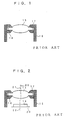
- Fig.1 shows a prior art of a one-lens system using a single lens.
- This one-lens system comprises a lens body 15 having a first face formed as a convex face and a second face formed as a convex face and has a positive power.
- the lens body 15 is put in position at inside part of one end of a lens barrel 16.
- a diaphragm 17 expanding inwardly from the lens barrel 16 is disposed at the one end of the cylinder 16 and holds the lens body 15 by putting it between the diaphragm 17 and a press member 18 disposed at a location on a rear side of the lens body 15.
- an image-pickup circuit 20 having an image-pickup element 19 such as CCD, CMOS and the like, is put in position at a location of the second face of the lens body 15 by adjusting an optical axis 21 of the lens body 15 and an optical axis 22 of the image-pickup element 19.
- the conventional image pickup lens system of such arrangement suffers from the following problems:
- the lens body 15 inserts in the lens barrel 16
- a very high accuracy of assembling and so much long assembling time are necessary and the manufacture cost is increased.
- the accuracy of the adjusting optical axes is deteriorated, a desired optical performance of lens is also deteriorated.
- any of these image pickup lens systems disclosed in the above Patent Applications is comprised of a lens body and a circular groove which is formed at a location of the center of the optical axis direction of the outer cylindrical surface of the lens body, has a wedge shape section and works as a diaphragm.
- any of such conventional image pickup lens systems suffers from a problem that F number of the lens system is more than 10 so that the lens system is very dark.
- the image pickup lens systems disclosed in Japanese Patent Application Laid-open No.6-250083 is used in a document reader device such as a scanner and the like, and the image pickup lens systems disclosed in Japanese Patent Application Laid-open No.5-273461 is used in a film with a lens, and these conventional image pickup lens systems can be applied to the document reader device and the film with a lens without any problem, but they can not be applied to a potable computer, a visual telephone, a cellular phone and the like, because these conventional systems are too dark.
- any of such conventional image pickup lens systems suffers from a problem that it is very difficult to lighten the lens system, because they consist of a lens body with a circular groove and they have no diaphragm. Moreover, they suffer from a problem that a stray light such as a flare and a ghost and the like easily occurs and this stray light is not eliminated completely. If a lens system becomes lighter, the problem of the occurrence of the stray light is more severe. Therefore, conventional image pickup lens systems are not used in a solid image-pickup element.
- an object of the present invention to provide an image pickup lens system, in which the numbers of the elements of the image pickup lens system are decreased, which can be produced easily and speedy, and in which a optical performance concerning the image pickup lens system is increased.
- an image pickup lens system comprising a lens body having a positive power and a diaphragm which is unified with the lens body at a location between the first face and the second face of the lens body and of which inner cylindrical surface is put in position at a location of the inside of the lens body.
- the lens body and the diaphragm are unified each other.
- the numbers of the elements of the image pickup lens system are decreased and the image pickup lens system can be produced accurately.
- both optical axes of the lens body and the diaphragm can be very accurately adjusted and automatically adjusted.
- a work to adjust accurately those optical axes is not necessary so that the lens body and the diaphragm can be produced easily and speedy.
- this invention can prevent the occurrence of the stray light such a flare and a ghost and the like and can actually remove the stray light if it occurs.
- an image pickup lens system comprising the diaphragm is unified with a lens barrel.
- the diaphragm and the lens barrel are unified each other.
- the numbers of the elements of the image pickup lens system are more decreased and the image pickup lens system can be produced more easily and speedy.
- an image pickup lens system comprising the inner cylindrical surface of the diaphragm has an acute angle end at a location of the first face side portion or the second face side portion of the lens body.
- the inner cylindrical surface of the diaphragm has an acute angle end at a location of the first face side portion or the second face side portion of the lens body.
- the diaphragm provides its appropriate function.
- the diaphragm is made of a material which has a similar or almost the same heat conductivity of the one of a molding die for molding the lens body.
- the diaphragm is made of a material which has a similar or almost the same heat conductivity of the one of a molding die for molding the lens body.
- an image pickup lens system comprising the diaphragm has a light shade which extends from diaphragm to the first face of the lens body along the outer cylindrical surface of the lens body.
- the diaphragm has the light shade which extends from diaphragm to the first face of the lens body along the outer cylindrical surface of the lens body.
- the light shade can remove an incident ray and a stray light on outer cylindrical surface of the lens.
- Fig.1 shows a basic arrangement of an image pickup lens system according to the present invention.
- the image pickup lens system of the present embodiment comprises a lens body 1 which has a positive power and is made of a resin such as plastics and the like.
- the lens body 1 includes convex faces formed on the first face located adjacent the object and the second face located adjacent the image of the lens body and has a positive power.
- the first lens 1 may be a double convex lens, or a meniscus concave lens having a flat face or a concave face on the side of the first face.
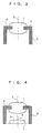
- a diaphragm 2 is unified with the lens body 1 at a location between the first face and the second face of the lens body 1 (in the middle of the optic axis direction of the outer surface of the lens body 1 shown in the Fig.3) and a inner cylindrical surface thereof is disposed at a location of the inside of the lens body 1.
- the diaphragm 2 in order to produce this lens body 1 having the diaphragm 2 unified therewith, the diaphragm 2 is put into a concave portion of a molding die for the lens body 1 at the first step, a melted resin is injected into the concave portion of the molding die at the next step, then the lens body 1 and the diaphragm 2 are unified with each other.
- the diaphragm 4 has a ring orifice 4 crossing at right angle to the optic axis of the lens body 1 and a lens barrel 5 unified with the ring orifice 4 expanding from the outer end portion of the ring orifice 4 to the second face of the lens of the lens body 1 along an optic axis 3 of the lens body 1.
- a cylindrical inner surface of the diaphragm 2 (ring orifice 4) runs parallel to the axis 3.
- the lens body 1 and the diaphragm 2 are unified each other and the diaphragm 2 and the lens barrel 5 are unified each other.
- the numbers of the elements of the image pickup lens system are decreased and the image pickup lens system can be produced accurately, in comparison with the prior art disposing the lens body 1, the diaphragm 2 and the lens barrel 5.
- both optical axes of the lens body and the diaphragm can be very accurately adjusted and automatically adjusted.
- a work to adjust accurately those optical axis as well as the prior art is not necessary so that the lens body 1 and the diaphragm 2 can be produced easily and speedy.
- this invention can prevent the occurrence of the stray light such a flare and a ghost and the like and can actually remove the stray light if it occurs.
- the diaphragm 2 is made of a metallic material which has a similar or almost the same heat conductivity of the one of a molding die for molding the lens body.
- the lens body 1 and the diaphragm 2 are unified each other so that the lens body 1 and the diaphragm 2 can be produced easily and speedy and the manufacture cost can be reduced.
- the image pickup lens systems can become lighter as like as the F number of the lens system is 2.5, an optical performance concerning the image pickup lens system is increased, and the image pickup lens systems can be easy to use.
- Fig.5 shows another embodiment of the present invention, in which the diaphragm 2 is formed a ring and unified with the lens body 1.
- the diaphragm 2 of the lens body 1 is mounted on the end of the lens barrel 5.
- the diaphragm 2 has more than one groove (not shown) at the outer surface thereof and the lens barrel 5 has more than one projection engaging the groove at one end thereof.
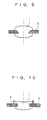
- Fig.6 and Fig. 7 show further another embodiment of the present invention, in which a cylindrical inner surface of the diaphragm 2 runs parallel with the optic axis 3.
- the lens body 1 includes a meniscus concave lens having one concave face with reference to Fig.6.
- the lens body 1 includes double convex faces and has a positive power with reference to Fig.7.
- the inner cylindrical surface of the diaphragm 2 has a slope making an acute angle end at a location of the object side portion thereof.
- the inner cylindrical surface of the diaphragm 2 has a slope making an acute angle end at a location of the image-pickup circuit 7 thereof.
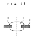
- the diaphragm 2 unified with the lens body 1 has a light shade 9 which extends from the diaphragm 2 to the end at a location of the object side portion of the lens body 1 along the outer cylindrical surface of the lens body 1.
- the light shade 9 can remove an incident ray and a stray light on outer cylindrical surface of the lens body 1.
- the diaphragm 2 unified with the lens body 1 has a light shade 9 which extends from the diaphragm 2 to the end at a location of the object side portion of the lens body 1 along the outer cylindrical surface of the lens body 1.
- the image pickup lens system of this invention can be produced easily and speedy, and in which a optical performance concerning the image pickup lens system is increased.
- Fig.12 shows Example 1 of the present invention, which is an image pickup lens system having the lens body 1 including a meniscus concave lens having a positive power and one concave face at a location of the object side portion, the inner cylindrical surface of the diaphragm 2 has a slope making an acute angle end at a location of the object side portion thereof. Moreover, a cover glass 30 is disposed at a location of the object side of the image-pickup element 6.
- Reference character 6a designates an image pickup surface of the image-pickup element 6 (in the same manner in Figs.13 and 14.) Face Radius r of curvature Distance d Refractive index nd Abbe number vd (1) Object 0.000 ⁇ (2) First face of lens body -8.423 0.2700 1.51800 56.0 (3) First face of diaphragm 0.000 0.5000 1.51800 56.0 (4) Second face of 0.000 1.23000 1.51800 56.0 diaphragm (5) Second face of lens body -1.981 0.0000 (6) First face of cover glass 0.000 1.0000 1.51680 64.2 (7) Second face of cover glass 0.000 4.1770 (8) CCD face 0.000 Face k A b 2 0.000000e+000 -8.118300e-002 2.585000e-001 5 -1.361950e+000 -1.830700e-002 -4.229000e-003 Face C d 2 -4.920100e-001 2.893100e+000 5 0.000
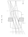
- Fig.13 shows Example 2 of the present invention, which is an image pickup lens system having the lens body 1 including a double convex lens having a positive power, the inner cylindrical surface of the diaphragm 2 has a slope making an acute angle end at a location of the object side portion thereof.
- the image pickup lens system of Example 2 is set under the following conditions: Face Radius r of curvature Distance d Refractive index nd Abbe number vd (1) Object 0.000 ⁇ (2) First face of lens body 2.782 1.0000 1.54300 56.0 (3) First face of diaphragm 0.000 0.5000 1.54300 56.0 (4) Second face of diaphragm 0.000 1.000 1.54300 56.0 (5) Second face of lens body -1.224 1.3720 (6) CCD face 0.000 Face K A b 2 0.000000e+000 -2.194640e-003 -2.504899e-003 5 -9.876386e+000 -2.599212e-001 1.395109e-001
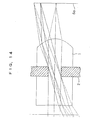
- Fig.14 shows Example 3 of the present invention, which is an image pickup lens system having the lens body 1 including a meniscus concave lens having a positive power and one concave face at a location of the object side portion, the cylindrical inner surface of the diaphragm 2 runs parallel with the optic axis.
- the image pickup lens system of Example 3 is set under the following conditions: Face Radius r of curvature Distance d Refractive index nd Abbe number ⁇ d (1) object 0.000 ⁇ (2) First face of lens body -8.633 1.5000 1.54300 56.0 (3) First face of diaphragm 0.000 0.5000 1.54300 56.0 (4) Second face of 0.000 1.5000 1.54300 56.0 diaphragm (5) Second face of lens body -0.905 1.8358 (6) CCD face 0.000 Face K A B 2 0.000000e+000 5.474060e-002 -1.815804e-002 5 -3.116156e+000 -2.163490e-001 5.074567e-002
- the distance d between the object and the first face of the lens body 1 was unlimited, however, the present invention can be applied to the image pickup lens system having a limited distance d.
Landscapes
- Physics & Mathematics (AREA)
- General Physics & Mathematics (AREA)
- Optics & Photonics (AREA)
- Lens Barrels (AREA)
- Lenses (AREA)
- Manufacturing Optical Record Carriers (AREA)
- Developing Agents For Electrophotography (AREA)
- Injection Moulding Of Plastics Or The Like (AREA)
Abstract
Description
| Face | Radius r of curvature | Distance d | Refractive index nd | Abbe number vd |
| (1) Object | 0.000 | ∞ | ||
| (2) First face of lens body | -8.423 | 0.2700 | 1.51800 | 56.0 |
| (3) First face of diaphragm | 0.000 | 0.5000 | 1.51800 | 56.0 |
| (4) Second face of | 0.000 | 1.23000 | 1.51800 | 56.0 |
| diaphragm | ||||
| (5) Second face of lens body | -1.981 | 0.0000 | ||
| (6) First face of cover glass | 0.000 | 1.0000 | 1.51680 | 64.2 |
| (7) Second face of cover glass | 0.000 | 4.1770 | ||
| (8) CCD face | 0.000 |
| Face | | A | b | |
| 2 | 0.000000e+000 | -8.118300e-002 | 2.585000e-001 | |
| 5 | -1.361950e+000 | -1.830700e-002 | -4.229000e-003 |
| Face | C | d |
| 2 | -4.920100e-001 | 2.893100e+000 |
| 5 | 0.000000e+000 | 0.000000e+000 |
| Face | Radius r of curvature | Distance d | Refractive index nd | Abbe number vd |
| (1) Object | 0.000 | ∞ | ||
| (2) First face of lens body | 2.782 | 1.0000 | 1.54300 | 56.0 |
| (3) First face of diaphragm | 0.000 | 0.5000 | 1.54300 | 56.0 |
| (4) Second face of diaphragm | 0.000 | 1.000 | 1.54300 | 56.0 |
| (5) Second face of lens body | -1.224 | 1.3720 | ||
| (6) CCD face | 0.000 |
| Face | | A | b | |
| 2 | 0.000000e+000 | -2.194640e-003 | -2.504899e-003 | |
| 5 | -9.876386e+000 | -2.599212e-001 | 1.395109e-001 |
| Face | Radius r of curvature | Distance d | Refractive index nd | Abbe number νd |
| (1) object | 0.000 | ∞ | ||
| (2) First face of lens body | -8.633 | 1.5000 | 1.54300 | 56.0 |
| (3) First face of diaphragm | 0.000 | 0.5000 | 1.54300 | 56.0 |
| (4) Second face of | 0.000 | 1.5000 | 1.54300 | 56.0 |
| diaphragm | ||||
| (5) Second face of lens body | -0.905 | 1.8358 | ||
| (6) CCD face | 0.000 |
| Face | | A | B | |
| 2 | 0.000000e+000 | 5.474060e-002 | -1.815804e-002 | |
| 5 | -3.116156e+000 | -2.163490e-001 | 5.074567e-002 |
Claims (5)
- An image pickup lens system comprising a lens body having a positive power and a diaphragm which is unified with the lens body at a location between the first face and the second face of the lens body and of which inner cylindrical surface is disposed at a location of the inside of the lens body.
- An image pickup lens system according to claim 1, wherein said diaphragm is unified with a lens barrel.
- An image pickup lens system according to claim 1 or claim 2, wherein said inner cylindrical surface of the diaphragm has an acute angle end at a location of the first face side portion or the second face side portion of the lens body.
- An image pickup lens system according to claim 1, claim 2 or claim 3, wherein said diaphragm is made of a material which has a similar or almost the same heat conductivity of the one of a molding die for molding the lens body.
- An image pickup lens system according to one of the claim 1 to claim 4, wherein said diaphragm has a light shade which extends from diaphragm to the first face of the lens body along the outer cylindrical surface of the lens body.
Applications Claiming Priority (2)
| Application Number | Priority Date | Filing Date | Title |
|---|---|---|---|
| JP2000170449 | 2000-06-07 | ||
| JP2000170449A JP2001350075A (en) | 2000-06-07 | 2000-06-07 | Imaging lens |
Publications (3)
| Publication Number | Publication Date |
|---|---|
| EP1162481A2 true EP1162481A2 (en) | 2001-12-12 |
| EP1162481A3 EP1162481A3 (en) | 2004-01-02 |
| EP1162481B1 EP1162481B1 (en) | 2006-04-26 |
Family
ID=18673169
Family Applications (1)
| Application Number | Title | Priority Date | Filing Date |
|---|---|---|---|
| EP01304987A Expired - Lifetime EP1162481B1 (en) | 2000-06-07 | 2001-06-07 | Method of making an image pickup lens system |
Country Status (5)
| Country | Link |
|---|---|
| US (1) | US6560040B2 (en) |
| EP (1) | EP1162481B1 (en) |
| JP (1) | JP2001350075A (en) |
| AT (1) | ATE324601T1 (en) |
| DE (1) | DE60119029T2 (en) |
Cited By (4)
| Publication number | Priority date | Publication date | Assignee | Title |
|---|---|---|---|---|
| EP1353207A3 (en) * | 2002-03-01 | 2004-01-21 | Agilent Technologies, Inc. (a Delaware Corporation) | Telecentric singlet having a small height requirement |
| EP1455211A3 (en) * | 2003-03-07 | 2004-09-15 | Alps Electric Co., Ltd. | Lens mount with an integrated lens |
| CN1302464C (en) * | 2003-05-31 | 2007-02-28 | 株式会社大宇电子 | Holographic ROM system |
| CN101932956A (en) * | 2007-07-03 | 2010-12-29 | 奥多麦卡有限公司 | Lens unit and camera module composed of different materials and method of manufacturing the same |
Families Citing this family (27)
| Publication number | Priority date | Publication date | Assignee | Title |
|---|---|---|---|---|
| JP4217415B2 (en) * | 2001-04-04 | 2009-02-04 | オリンパス株式会社 | Electronic imaging device |
| US7126945B2 (en) * | 2001-11-07 | 2006-10-24 | Symbol Technologies, Inc. | Power saving function for wireless LANS: methods, system and program products |
| JP4508521B2 (en) * | 2002-07-16 | 2010-07-21 | オリンパス株式会社 | Imaging device |
| US6898026B2 (en) * | 2003-08-11 | 2005-05-24 | 3M Innovative Properties Company | Optical element |
| JP2005070413A (en) * | 2003-08-25 | 2005-03-17 | Alps Electric Co Ltd | Optical element equipped with holder, and manufacture of the same |
| US7540671B2 (en) * | 2003-11-17 | 2009-06-02 | Olympus Corporation | Variable-power optical system and electronic device using same |
| JP2005148614A (en) * | 2003-11-19 | 2005-06-09 | Olympus Corp | Variable magnification optical system and electronic apparatus using the same |
| JP2005156829A (en) * | 2003-11-25 | 2005-06-16 | Olympus Corp | Variable magnification optical system and electronic apparatus using the same |
| JP2005156828A (en) * | 2003-11-25 | 2005-06-16 | Olympus Corp | Variable magnification optical system and electronic apparatus using the same |
| JP4508610B2 (en) * | 2003-11-17 | 2010-07-21 | オリンパス株式会社 | Variable magnification optical system and electronic apparatus using the same |
| JP4481750B2 (en) * | 2004-07-08 | 2010-06-16 | 日本板硝子株式会社 | Method for manufacturing optical component with holder |
| DE502005002762D1 (en) * | 2005-06-22 | 2008-03-20 | Roche Diagnostics Gmbh | Analysis system for analyzing a sample on an analytical test element |
| US7352519B2 (en) * | 2005-08-03 | 2008-04-01 | Symbol Technologies, Inc. | Lens module |
| JP2007133197A (en) * | 2005-11-11 | 2007-05-31 | Olympus Corp | Optical component and its manufacture method |
| TWI400473B (en) * | 2007-11-30 | 2013-07-01 | Hon Hai Prec Ind Co Ltd | Plastic lens and method for manufacturing the same |
| JP2009080500A (en) * | 2008-12-05 | 2009-04-16 | Canon Inc | Molded lens with aperture stop |
| JP5312968B2 (en) * | 2009-02-02 | 2013-10-09 | オリンパス株式会社 | Optical component and method of manufacturing optical component |
| DE102009047361B4 (en) * | 2009-12-01 | 2013-02-07 | Fraunhofer-Gesellschaft zur Förderung der angewandten Forschung e.V. | Device for optical imaging |
| NL2006373C2 (en) * | 2011-03-11 | 2012-09-17 | Anteryon Internat B V | OPTICAL UNIT. |
| CN105372771B (en) * | 2015-12-16 | 2018-10-19 | 武汉优信技术股份有限公司 | A kind of optical module optical interface assemblies with collimation lens |
| JP6576393B2 (en) * | 2016-07-29 | 2019-09-18 | キヤノン株式会社 | OPTICAL COMPONENT, OPTICAL COMPONENT MANUFACTURING METHOD, CAMERA, AND FINDER |
| US20180315894A1 (en) * | 2017-04-26 | 2018-11-01 | Advanced Semiconductor Engineering, Inc. | Semiconductor device package and a method of manufacturing the same |
| US10969560B2 (en) * | 2017-05-04 | 2021-04-06 | Lightpath Technologies, Inc. | Integrated optical assembly and manufacturing the same |
| JP2019090849A (en) * | 2017-11-10 | 2019-06-13 | カンタツ株式会社 | Optical element and image capturing lens |
| JP6964050B2 (en) * | 2018-07-20 | 2021-11-10 | オリンパス株式会社 | Manufacturing method of optical element |
| JP7197354B2 (en) * | 2018-12-28 | 2022-12-27 | Hoya株式会社 | LENS UNIT AND METHOD OF MANUFACTURING LENS UNIT |
| JP2022185161A (en) * | 2019-11-21 | 2022-12-14 | パナソニックIpマネジメント株式会社 | Infrared lens and imaging apparatus |
Family Cites Families (11)
| Publication number | Priority date | Publication date | Assignee | Title |
|---|---|---|---|---|
| JPH0756707B2 (en) * | 1983-09-16 | 1995-06-14 | オリンパス光学工業株式会社 | Manufacturing method of lens with carrier |
| JPS62145201A (en) * | 1985-12-20 | 1987-06-29 | Hitachi Ltd | plastic cleanse |
| JPH03167514A (en) * | 1989-11-28 | 1991-07-19 | Fujitsu Ltd | Molded lens with metallic holder and production thereof and optical semiconductor module provided with the lens |
| JPH0566302A (en) * | 1991-09-09 | 1993-03-19 | Nec Corp | Fresnel lens structure |
| US5274502A (en) * | 1991-10-31 | 1993-12-28 | Corning Incorporated | Molded lens with integral mount and method |
| JPH06250083A (en) * | 1993-03-02 | 1994-09-09 | Nippon Hikyumen Lens Kk | Reduction optics |
| JP3353958B2 (en) * | 1993-07-30 | 2002-12-09 | オリンパス光学工業株式会社 | Optical element manufacturing method |
| JP2907016B2 (en) * | 1994-09-05 | 1999-06-21 | 松下電器産業株式会社 | Optical element |
| JP3485685B2 (en) * | 1995-08-04 | 2004-01-13 | オリンパス株式会社 | Refractive index single lens |
| JPH11264930A (en) * | 1998-03-17 | 1999-09-28 | Olympus Optical Co Ltd | Optical system and optical module |
| JP2000147346A (en) * | 1998-11-09 | 2000-05-26 | Toshiba Corp | Mounting mechanism for molded lenses |
-
2000
- 2000-06-07 JP JP2000170449A patent/JP2001350075A/en active Pending
-
2001
- 2001-06-06 US US09/876,302 patent/US6560040B2/en not_active Expired - Lifetime
- 2001-06-07 EP EP01304987A patent/EP1162481B1/en not_active Expired - Lifetime
- 2001-06-07 AT AT01304987T patent/ATE324601T1/en not_active IP Right Cessation
- 2001-06-07 DE DE60119029T patent/DE60119029T2/en not_active Expired - Lifetime
Cited By (7)
| Publication number | Priority date | Publication date | Assignee | Title |
|---|---|---|---|---|
| EP1353207A3 (en) * | 2002-03-01 | 2004-01-21 | Agilent Technologies, Inc. (a Delaware Corporation) | Telecentric singlet having a small height requirement |
| EP1455211A3 (en) * | 2003-03-07 | 2004-09-15 | Alps Electric Co., Ltd. | Lens mount with an integrated lens |
| US7180688B2 (en) | 2003-03-07 | 2007-02-20 | Alps Electric Co., Ltd. | Holder/optical-element assembly |
| CN1302464C (en) * | 2003-05-31 | 2007-02-28 | 株式会社大宇电子 | Holographic ROM system |
| CN101932956A (en) * | 2007-07-03 | 2010-12-29 | 奥多麦卡有限公司 | Lens unit and camera module composed of different materials and method of manufacturing the same |
| EP2165225A4 (en) * | 2007-07-03 | 2012-05-09 | Optomecha Co Ltd | Lens unit composed of different materials and camera module and method for manufacturing the same |
| CN101932956B (en) * | 2007-07-03 | 2013-11-13 | 奥多麦卡有限公司 | Lens unit and camera module made of different materials and manufacturing method thereof |
Also Published As
| Publication number | Publication date |
|---|---|
| US6560040B2 (en) | 2003-05-06 |
| EP1162481B1 (en) | 2006-04-26 |
| EP1162481A3 (en) | 2004-01-02 |
| DE60119029T2 (en) | 2007-05-10 |
| US20020075573A1 (en) | 2002-06-20 |
| JP2001350075A (en) | 2001-12-21 |
| ATE324601T1 (en) | 2006-05-15 |
| DE60119029D1 (en) | 2006-06-01 |
Similar Documents
| Publication | Publication Date | Title |
|---|---|---|
| US6560040B2 (en) | Image pickup lens system | |
| US20230400669A1 (en) | Lens module | |
| US6466377B1 (en) | Image pickup lens system | |
| US6560043B1 (en) | Image pickup lens system | |
| US11125977B2 (en) | High-resolution wide angle lens system | |
| US5940219A (en) | Imaging lens | |
| US6891684B2 (en) | Image taking lens system | |
| EP1426805B1 (en) | Imaging lens system | |
| KR102908334B1 (en) | Imaging Lens System | |
| JP3753183B1 (en) | Imaging lens | |
| US6297915B1 (en) | Image pickup lens | |
| US7110189B2 (en) | Photographing lens having three lens element | |
| TWI383188B (en) | Camera lens | |
| CN101178475A (en) | Zoom lens system and optical apparatus using the same | |
| US6853504B2 (en) | Camera lens system for image pickup devices | |
| EP1367422A2 (en) | Wide-angle optical system for solid image pickup element | |
| EP1335227A2 (en) | Image pickup lens | |
| JP2003195162A (en) | Wide lens and manufacturing method thereof | |
| EP1382986B1 (en) | Imaging lens system | |
| KR20220164389A (en) | Optical image capturing lens | |
| US12386137B2 (en) | Imaging lens assembly, imaging lens assembly module, camera module and electronic device | |
| EP1312941A1 (en) | Image pickup lens | |
| KR20250062126A (en) | Imaging Lens System | |
| JP2005091513A (en) | Optical lens for imaging camera | |
| JP3593530B2 (en) | Imaging lens |
Legal Events
| Date | Code | Title | Description |
|---|---|---|---|
| PUAI | Public reference made under article 153(3) epc to a published international application that has entered the european phase |
Free format text: ORIGINAL CODE: 0009012 |
|
| AK | Designated contracting states |
Kind code of ref document: A2 Designated state(s): AT BE CH CY DE DK ES FI FR GB GR IE IT LI LU MC NL PT SE TR |
|
| AX | Request for extension of the european patent |
Free format text: AL;LT;LV;MK;RO;SI |
|
| PUAL | Search report despatched |
Free format text: ORIGINAL CODE: 0009013 |
|
| AK | Designated contracting states |
Kind code of ref document: A3 Designated state(s): AT BE CH CY DE DK ES FI FR GB GR IE IT LI LU MC NL PT SE TR |
|
| AX | Request for extension of the european patent |
Extension state: AL LT LV MK RO SI |
|
| RIC1 | Information provided on ipc code assigned before grant |
Ipc: 7G 02B 7/02 B Ipc: 7B 29D 11/00 B Ipc: 7G 02B 3/00 A Ipc: 7H 04N 5/225 B |
|
| 17P | Request for examination filed |
Effective date: 20040413 |
|
| 17Q | First examination report despatched |
Effective date: 20040608 |
|
| AKX | Designation fees paid |
Designated state(s): AT BE CH CY DE DK ES FI FR GB GR IE IT LI LU MC NL PT SE TR |
|
| GRAP | Despatch of communication of intention to grant a patent |
Free format text: ORIGINAL CODE: EPIDOSNIGR1 |
|
| RTI1 | Title (correction) |
Free format text: METHOD OF MAKING AN IMAGE PICKUP LENS SYSTEM |
|
| GRAS | Grant fee paid |
Free format text: ORIGINAL CODE: EPIDOSNIGR3 |
|
| GRAA | (expected) grant |
Free format text: ORIGINAL CODE: 0009210 |
|
| AK | Designated contracting states |
Kind code of ref document: B1 Designated state(s): AT BE CH CY DE DK ES FI FR GB GR IE IT LI LU MC NL PT SE TR |
|
| PG25 | Lapsed in a contracting state [announced via postgrant information from national office to epo] |
Ref country code: IT Free format text: LAPSE BECAUSE OF FAILURE TO SUBMIT A TRANSLATION OF THE DESCRIPTION OR TO PAY THE FEE WITHIN THE PRESCRIBED TIME-LIMIT;WARNING: LAPSES OF ITALIAN PATENTS WITH EFFECTIVE DATE BEFORE 2007 MAY HAVE OCCURRED AT ANY TIME BEFORE 2007. THE CORRECT EFFECTIVE DATE MAY BE DIFFERENT FROM THE ONE RECORDED. Effective date: 20060426 Ref country code: CH Free format text: LAPSE BECAUSE OF FAILURE TO SUBMIT A TRANSLATION OF THE DESCRIPTION OR TO PAY THE FEE WITHIN THE PRESCRIBED TIME-LIMIT Effective date: 20060426 Ref country code: LI Free format text: LAPSE BECAUSE OF FAILURE TO SUBMIT A TRANSLATION OF THE DESCRIPTION OR TO PAY THE FEE WITHIN THE PRESCRIBED TIME-LIMIT Effective date: 20060426 Ref country code: NL Free format text: LAPSE BECAUSE OF FAILURE TO SUBMIT A TRANSLATION OF THE DESCRIPTION OR TO PAY THE FEE WITHIN THE PRESCRIBED TIME-LIMIT Effective date: 20060426 Ref country code: BE Free format text: LAPSE BECAUSE OF FAILURE TO SUBMIT A TRANSLATION OF THE DESCRIPTION OR TO PAY THE FEE WITHIN THE PRESCRIBED TIME-LIMIT Effective date: 20060426 Ref country code: FI Free format text: LAPSE BECAUSE OF FAILURE TO SUBMIT A TRANSLATION OF THE DESCRIPTION OR TO PAY THE FEE WITHIN THE PRESCRIBED TIME-LIMIT Effective date: 20060426 Ref country code: AT Free format text: LAPSE BECAUSE OF FAILURE TO SUBMIT A TRANSLATION OF THE DESCRIPTION OR TO PAY THE FEE WITHIN THE PRESCRIBED TIME-LIMIT Effective date: 20060426 |
|
| REG | Reference to a national code |
Ref country code: GB Ref legal event code: FG4D |
|
| REG | Reference to a national code |
Ref country code: IE Ref legal event code: FG4D |
|
| REF | Corresponds to: |
Ref document number: 60119029 Country of ref document: DE Date of ref document: 20060601 Kind code of ref document: P |
|
| PG25 | Lapsed in a contracting state [announced via postgrant information from national office to epo] |
Ref country code: IE Free format text: LAPSE BECAUSE OF NON-PAYMENT OF DUE FEES Effective date: 20060607 |
|
| PG25 | Lapsed in a contracting state [announced via postgrant information from national office to epo] |
Ref country code: MC Free format text: LAPSE BECAUSE OF NON-PAYMENT OF DUE FEES Effective date: 20060630 |
|
| PG25 | Lapsed in a contracting state [announced via postgrant information from national office to epo] |
Ref country code: DK Free format text: LAPSE BECAUSE OF FAILURE TO SUBMIT A TRANSLATION OF THE DESCRIPTION OR TO PAY THE FEE WITHIN THE PRESCRIBED TIME-LIMIT Effective date: 20060726 Ref country code: SE Free format text: LAPSE BECAUSE OF FAILURE TO SUBMIT A TRANSLATION OF THE DESCRIPTION OR TO PAY THE FEE WITHIN THE PRESCRIBED TIME-LIMIT Effective date: 20060726 |
|
| PG25 | Lapsed in a contracting state [announced via postgrant information from national office to epo] |
Ref country code: ES Free format text: LAPSE BECAUSE OF FAILURE TO SUBMIT A TRANSLATION OF THE DESCRIPTION OR TO PAY THE FEE WITHIN THE PRESCRIBED TIME-LIMIT Effective date: 20060806 |
|
| PG25 | Lapsed in a contracting state [announced via postgrant information from national office to epo] |
Ref country code: PT Free format text: LAPSE BECAUSE OF FAILURE TO SUBMIT A TRANSLATION OF THE DESCRIPTION OR TO PAY THE FEE WITHIN THE PRESCRIBED TIME-LIMIT Effective date: 20060926 |
|
| REG | Reference to a national code |
Ref country code: CH Ref legal event code: PL |
|
| NLV1 | Nl: lapsed or annulled due to failure to fulfill the requirements of art. 29p and 29m of the patents act | ||
| ET | Fr: translation filed | ||
| PLBE | No opposition filed within time limit |
Free format text: ORIGINAL CODE: 0009261 |
|
| STAA | Information on the status of an ep patent application or granted ep patent |
Free format text: STATUS: NO OPPOSITION FILED WITHIN TIME LIMIT |
|
| 26N | No opposition filed |
Effective date: 20070129 |
|
| PG25 | Lapsed in a contracting state [announced via postgrant information from national office to epo] |
Ref country code: GR Free format text: LAPSE BECAUSE OF FAILURE TO SUBMIT A TRANSLATION OF THE DESCRIPTION OR TO PAY THE FEE WITHIN THE PRESCRIBED TIME-LIMIT Effective date: 20060727 |
|
| PG25 | Lapsed in a contracting state [announced via postgrant information from national office to epo] |
Ref country code: TR Free format text: LAPSE BECAUSE OF FAILURE TO SUBMIT A TRANSLATION OF THE DESCRIPTION OR TO PAY THE FEE WITHIN THE PRESCRIBED TIME-LIMIT Effective date: 20060426 Ref country code: LU Free format text: LAPSE BECAUSE OF NON-PAYMENT OF DUE FEES Effective date: 20060607 |
|
| PG25 | Lapsed in a contracting state [announced via postgrant information from national office to epo] |
Ref country code: CY Free format text: LAPSE BECAUSE OF FAILURE TO SUBMIT A TRANSLATION OF THE DESCRIPTION OR TO PAY THE FEE WITHIN THE PRESCRIBED TIME-LIMIT Effective date: 20060426 |
|
| REG | Reference to a national code |
Ref country code: FR Ref legal event code: PLFP Year of fee payment: 16 |
|
| PGFP | Annual fee paid to national office [announced via postgrant information from national office to epo] |
Ref country code: GB Payment date: 20160621 Year of fee payment: 16 Ref country code: DE Payment date: 20160621 Year of fee payment: 16 |
|
| PGFP | Annual fee paid to national office [announced via postgrant information from national office to epo] |
Ref country code: FR Payment date: 20160627 Year of fee payment: 16 |
|
| REG | Reference to a national code |
Ref country code: DE Ref legal event code: R119 Ref document number: 60119029 Country of ref document: DE |
|
| GBPC | Gb: european patent ceased through non-payment of renewal fee |
Effective date: 20170607 |
|
| REG | Reference to a national code |
Ref country code: FR Ref legal event code: ST Effective date: 20180228 |
|
| PG25 | Lapsed in a contracting state [announced via postgrant information from national office to epo] |
Ref country code: DE Free format text: LAPSE BECAUSE OF NON-PAYMENT OF DUE FEES Effective date: 20180103 Ref country code: GB Free format text: LAPSE BECAUSE OF NON-PAYMENT OF DUE FEES Effective date: 20170607 |
|
| PG25 | Lapsed in a contracting state [announced via postgrant information from national office to epo] |
Ref country code: FR Free format text: LAPSE BECAUSE OF NON-PAYMENT OF DUE FEES Effective date: 20170630 |