EP1162469A2 - Current monitoring and latchup detection circuit and method - Google Patents
Current monitoring and latchup detection circuit and method Download PDFInfo
- Publication number
- EP1162469A2 EP1162469A2 EP01304419A EP01304419A EP1162469A2 EP 1162469 A2 EP1162469 A2 EP 1162469A2 EP 01304419 A EP01304419 A EP 01304419A EP 01304419 A EP01304419 A EP 01304419A EP 1162469 A2 EP1162469 A2 EP 1162469A2
- Authority
- EP
- European Patent Office
- Prior art keywords
- current
- difference
- power supply
- output signal
- drain
- Prior art date
- Legal status (The legal status is an assumption and is not a legal conclusion. Google has not performed a legal analysis and makes no representation as to the accuracy of the status listed.)
- Granted
Links
Images



Classifications
-
- G—PHYSICS
- G01—MEASURING; TESTING
- G01R—MEASURING ELECTRIC VARIABLES; MEASURING MAGNETIC VARIABLES
- G01R31/00—Arrangements for testing electric properties; Arrangements for locating electric faults; Arrangements for electrical testing characterised by what is being tested not provided for elsewhere
- G01R31/28—Testing of electronic circuits, e.g. by signal tracer
- G01R31/30—Marginal testing, e.g. by varying supply voltage
- G01R31/3004—Current or voltage test
Definitions
- the present invention is generally directed to a current monitoring circuit and, more specifically, to a circuit capable of detecting a latchup condition or other over-current condition using a magnetic field detection transistor (or magFET).
- magFET magnetic field detection transistor
- the power and complexity of integrated circuits has increased dramatically in the last twenty years. This complexity has increased the likelihood of a manufacturing defect occurring on the chip. It also has increased the likelihood that a poor chip design may make the integrated circuit more susceptible to error conditions, such as latch-up, during times when the integrated circuit is operating under adverse conditions, such as high noise, power supply over-voltage conditions, high temperature, and the like.
- a common technique for screening integrated circuits (IC) is to measure the I DDQ of an integrated circuit under test. I DDQ is the power supply current in a quiescent operating condition. Faulty integrated circuits have a different I DDQ signature compared to non-faulty integrated circuits.
- BIST built-in self test
- BIST built-in self test
- the apparatus comprises: 1) a Lorentz force MOS transistor having a first drain current (ID1) and a second drain current (ID2), wherein the Lorentz force MOS transistor is disposed proximate the wire carrying the load current and wherein a magnetic force generated by the load current increases a first current difference between the first drain current and the second drain current; and 2) a current difference amplification circuit capable of detecting the first current difference between the first drain current and the second drain current and generating an amplified output signal.
- ID1 first drain current
- ID2 second drain current
- a current difference amplification circuit capable of detecting the first current difference between the first drain current and the second drain current and generating an amplified output signal.
- the apparatus further comprises a current monitoring circuit coupled to the current difference amplification circuit capable of detecting and measuring the amplified output signal.
- the current monitoring circuit compares the amplified output signal to a predetermined threshold level and generates an error signal if the amplified output signal exceeds the predetermined threshold level.
- the apparatus further comprises a switch controlled by the current monitoring circuit capable of coupling the wire to a power supply.
- the current monitoring circuit opens the switch and measures the amplified output signal when the load current is zero to thereby determine an initial current difference reference.
- the current monitoring circuit closes the switch and measures the amplified output signal to determine the first current difference.
- the Lorentz force MOS transistor is disposed within a loop formed by the wire.
- the Lorentz force MOS transistor is disposed within a plurality of concentric loops formed by the wire.
- FIGURES 1 through 5 discussed below, and the various embodiments used to describe the principles of the present invention in this patent document are by way of illustration only and should not be construed in any way to limit the scope of the invention. Those skilled in the art will understand that the principles of the present invention may be implemented in any suitably arranged current monitoring circuit.
- FIGURE 1 illustrates exemplary prior art magnetic field detection transistor (or magFET) 100.
- MagFET 100 comprises source 110, gate 120, drain 130 and drain 140.
- MagFET 100 is similar to a normal metal-oxide-silicon (MOS) transistor, except for the split drain.
- Source 110 contains contact pad 111
- drain 130 contains contact pad 131
- drain 140 contains contact pad 141.
- Source current (I s ) flows from contact pad 111 towards contact pads 131 and 141 in the split drain. If no external magnetic field is applied, the source current splits evenly between the drains.
- FIGURE 2 illustrates exemplary current difference detection circuit 200 using exemplary magFET 100 according to one embodiment of the present invention.
- Current difference detection circuit 200 is designed to detect and amplify any difference in the drain currents, I d1 and I d2 , in magFET 100.
- Current difference detection circuit 200 comprises p-type transistors 205, 210, 215, 220 and 225, p-type transistor 230, current source 240 and magFET 100, which also is an n-type transistor.
- the split drains 130 and 140 of magFET 100 are labeled D1 and D2, respectively.
- Current source 240 creates a reference current, I ref , that flows through transistor 205 and transistor 230.
- the gates of transistor 230 and magFET 100 are connected together, so that the same gate-to-source bias voltage, V gs , appears across transistor 230 and magFET 100. This forces the drain-to-source current in magFET 100 to be equal to the drain-to-source current in transistor 230, namely I ref .
- the sum of the split drain currents i.e., I d1 + I d2 ) is equal to I ref .
- the drain currents, I d1 and I d2 are equal to each other, so that one-half of I ref flows into each drain of magFET 100.
- 1 ⁇ 2(I ref ) flows through the circuit branch comprising transistors 210 and 220 and 1 ⁇ 2(I ref ) flows through the circuit branch comprising transistors 215 and 225.
- drain currents I d1 and I d2 The difference between the drain currents, I d1 and I d2 , does not have to be zero initially.
- the drain currents I d1 and I d2 may initially be deliberately unbalanced, thereby creating an initial non-zero ⁇ V reference point.
- transistors 210 and 215 may be fabricated slightly differently, which creates an imbalance in the magnitudes of currents I d1 and I d2 through magFET 100.
- trim block 216 may be inserted between the gates of transistors 210 and 215. Trim block 216 creates a slight voltage difference between the gates of transistors 210 and 215, thereby creating an imbalance in the magnitudes of currents I d1 and I d2 through magFET 100.
- a current-carrying wire is disposed on or near magFET 100
- the current in the wire causes a magnetic field that creates (or increases) a difference in the drain currents, I d1 and I d2 .
- the currents in the two current branches coupled to drains D1 and D2 are no longer equal and a voltage difference appears between nodes V1 and V2.
- the greater the current in the wire overlaid on or near magFET 100 the greater the magnetic field caused by the wire and the greater the difference in the drain currents, I d1 and I d2 .
- the initial imbalance in the magnitudes of currents I d1 and I d2 through magFET 100 may be overcome by the magnetically induced current difference, thereby causing a difference in the state of the circuit and indicating an over-current condition.
- current difference detection circuit 200 comprises only a single magFET capable of detecting current in a wire.
- current difference detection circuit 200 may comprise two or more magFETs similar to magFET 100 that are coupled in series or in parallel, or in a combination of series and parallel magFETs.
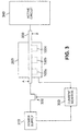
- FIGURE 3 illustrates exemplary integrated circuit (IC) 300, which contains monitoring circuitry that monitors the current drawn by active circuit 390 and detects a latchup or other over-current condition, according to one embodiment of the present invention.
- Integrated circuit 300 comprises power supply 310, which supplies power to active circuit 340 via wire 330 and switch 320.
- Active circuit 340 is not intended to be any particular type of electronic circuit.
- Wire 330 is formed by the metallization layers in the semiconductor.
- Active circuit 340 may be the CPU logic of a microprocessor, a random access memory (RAM), a digital signal processor, a radio frequency (RF) transceiver, or the like.
- RAM random access memory
- RF radio frequency
- the monitoring circuitry comprises current difference detection circuit 200, current monitor 350, and switch 320. These elements monitor the level of current in wire 330 in order to detect a latch-up or other over-current condition.
- Current difference detection circuit 200 comprises a plurality of magFETs for detecting current in wire 330, including exemplary magFET 100a, exemplary magFET 100b, and exemplary magFET 100c, which may be arranged in parallel, in series, or in a parallel and series combination.
- switch 320 When switch 320 is closed, current flows from power supply 310 to active circuit 340 through wire 330 (i.e., from node A to node B).
- the current in wire 330 creates a magnetic field that is sensed by magFETs 100a-c, which produce a difference voltage signal, ⁇ V, that is read by current monitor 350.
- Current monitor 350 comprises processing circuitry capable of measuring and storing the difference voltage ⁇ V, comparing it to one or more predetermined threshold values, and determining whether or not a latch-up or other over-current condition exists. The greater the value of ⁇ V, the more likely a latch-up or over-current condition exists.
- FIGURES 4A and 4B illustrate different configurations 400 and 450 of current-carrying wire 330 monitored by exemplary magFET 100 according to alternate embodiments of the present invention.
- the magnetic field created in magFET 100 by the current in wire 330 may be increased by looping the wire around magFET 100 as shown in FIRE 4A.
- Current flows from node A to node B and creates a larger magnetic field because of the amount of wire in close proximity to magFET 100.
- Increasing the magnetic field increases the magnitude of the difference voltage signal, ⁇ V, that is read by current monitor 350.
- FIGURE 4B shows a more extreme example.
- Current in wire 330 flows from node A to node B and makes many loops around magFET 100. Each loop adds to the size of the magnetic field and, therefore, increases the magnitude of the difference voltage signal, ⁇ V, read by current monitor 350.
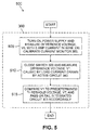
- FIGURE 5 depicts flow diagram 500, which illustrates the operation of exemplary monitoring circuit 300 according to one embodiment of the present invention.
- no power is applied to integrated circuit 300 and switch 320 is open.
- power supply 310 comes on and provides power to current monitor 350 and current difference detection circuit 200.
- Current monitor 350 measures the difference voltage, V0, from current difference detection circuit 200 when no current is flowing in wire 330. This permits calibration of current monitor 350 for no load conditions (process step 505).
- current monitor 350 closes switch 320 so that current flows through wire 330 and into active circuit 340.
- the load current in wire 330 drawn by active circuit 340 creates a magnetic field that causes drain current differences in one or more of magFETs 100a-c100c.
- the current differences are detected by current difference detection circuit 200, which generates a corresponding difference voltage, V1, that is measured by current monitor 300 (process step 510).
- current monitor 300 compares the measured difference voltage, V1 to a predetermined threshold voltage, VT, and passes or fails integrated circuit 300 by generating an error (or fail) signal or a pass signal accordingly (process ⁇ step 515).
Landscapes
- Engineering & Computer Science (AREA)
- General Engineering & Computer Science (AREA)
- Physics & Mathematics (AREA)
- General Physics & Mathematics (AREA)
- Semiconductor Integrated Circuits (AREA)
- Measurement Of Current Or Voltage (AREA)
Abstract
Description
Claims (14)
- An apparatus for monitoring a load current drawn by an electrical circuit in a wire comprising:a Lorentz force MOS transistor having a first drain current (ID1) and a second drain current (ID2), wherein said Lorentz force MOS transistor is disposed proximate said wire carrying said load current and wherein a magnetic force generated by said load current increases a first current difference between said first drain current and said second drain current; anda current difference amplification circuit capable of detecting said first current difference between said first drain current and said second drain current and generating an amplified output signal.
- An integrated circuit comprising:an electrical circuit capable of drawing a load current when said electrical circuit is active;a power supply capable of supplying said load current to said electrical circuit;a power supply wire for carrying said load current from said power supply to said electrical circuit; andan apparatus for monitoring said load current drawn by said electrical circuit in said power supply wire comprising:a Lorentz force MOS transistor having a first drain current (ID1) and a second drain current (ID2), wherein said Lorentz force MOS transistor is disposed proximate said power supply wire carrying said load current and wherein a magnetic force generated by said load current increases a first current difference between said first drain current and said second drain current; anda current difference amplification circuit capable of detecting said first current difference between said first drain current and said second drain current and generating an amplified output signal.
- The integrated circuit or apparatus as set forth in Claim 1 or Claim 2 further comprising a current monitoring circuit coupled to said current difference amplification circuit capable of detecting and measuring said amplified output signal.
- The integrated circuit or apparatus as set forth in Claim 3 wherein said current monitoring circuit compares said amplified output signal to a predetermined threshold level and generates an error signal if said amplified output signal exceeds said predetermined threshold level.
- The integrated circuit or apparatus as set forth in Claim 4 further comprising a switch controlled by said current monitoring circuit capable of coupling said wire to a power supply.
- The integrated circuit or apparatus as set forth in Claim 5 wherein said current monitoring circuit opens said switch and measures said amplified output signal when said load current is zero to thereby determine an initial current difference reference.
- The integrated circuit or apparatus as set forth in Claim 6 wherein said current monitoring circuit closes said switch and measures said amplified output signal to determine said first current difference.
- The integrated circuit or apparatus as set forth in Claim 1 or Claim 2 wherein said Lorentz force MOS transistor is disposed within a loop formed by said wire.
- The integrated circuit or apparatus as set forth in Claim 8 wherein said Lorentz force MOS transistor is disposed within a plurality of concentric loops formed by said power supply wire.
- A method for monitoring a load current in a power supply wire coupling a power supply and electrical circuit, wherein the wire is disposed proximate a Lorentz force MOS transistor having a first drain current (ID1) and a second drain current (ID2), the method comprising the steps of:opening a switch coupling the power supply and the electrical circuit to thereby set the load current to zero;detecting an initial current difference between the first drain current and the second drain current;closing the switch to thereby establish a non-zero load current, the non-zero load current generating a magnetic force that creates a first current difference between the first drain current and the second drain current;detecting the first current difference between the first drain current and the second drain current; andgenerating an output signal corresponding to the first current difference.
- The method as set forth in Claim 10 wherein the steps of detecting the first current difference and generating the output signal comprises the sub-steps of amplifying the first current difference in a differential amplifier stage and generating a differential output voltage corresponding to the first current difference.
- The method as set forth in Claim 10 further comprising the steps of comparing the amplified output signal to a predetermined threshold level and generating an error signal if the amplified output signal exceeds the predetermined threshold level.
- The method as set forth in Claim 10 wherein the Lorentz force MOS transistor is disposed within a loop formed by the power supply wire.
- The method as set forth in Claim 13 wherein the Lorentz force MOS transistor is disposed within a plurality of concentric loops formed by the power supply wire.
Applications Claiming Priority (2)
| Application Number | Priority Date | Filing Date | Title |
|---|---|---|---|
| US590499 | 2000-06-09 | ||
| US09/590,499 US6469538B1 (en) | 2000-06-09 | 2000-06-09 | Current monitoring and latchup detection circuit and method of operation |
Publications (3)
| Publication Number | Publication Date |
|---|---|
| EP1162469A2 true EP1162469A2 (en) | 2001-12-12 |
| EP1162469A3 EP1162469A3 (en) | 2002-11-06 |
| EP1162469B1 EP1162469B1 (en) | 2007-01-31 |
Family
ID=24362507
Family Applications (1)
| Application Number | Title | Priority Date | Filing Date |
|---|---|---|---|
| EP01304419A Expired - Lifetime EP1162469B1 (en) | 2000-06-09 | 2001-05-18 | Current monitoring and latchup detection circuit and method |
Country Status (3)
| Country | Link |
|---|---|
| US (1) | US6469538B1 (en) |
| EP (1) | EP1162469B1 (en) |
| DE (1) | DE60126376D1 (en) |
Families Citing this family (7)
| Publication number | Priority date | Publication date | Assignee | Title |
|---|---|---|---|---|
| TWI240078B (en) * | 2001-11-09 | 2005-09-21 | Macronix Int Co Ltd | Circuit for measuring capacitance and measuring method using the same |
| US6985002B2 (en) * | 2003-06-05 | 2006-01-10 | Texas Instruments Incorporated | System and method for input/output induced latch up detection |
| EP1560030A1 (en) * | 2004-01-28 | 2005-08-03 | Koninklijke Philips Electronics N.V. | Method and apparatus for testing integrated circuits for susceptibility to latch-up |
| US7483248B1 (en) * | 2005-05-19 | 2009-01-27 | Sun Microsystems, Inc. | Method and apparatus for detecting current changes in integrated circuits |
| US9625520B2 (en) * | 2015-07-06 | 2017-04-18 | Macronix International Co., Ltd. | Latch-up test device and method for testing wafer under test |
| EP3244532A1 (en) * | 2016-05-10 | 2017-11-15 | Université de Strasbourg | Magnetic operational amplifier |
| KR20220136754A (en) | 2021-04-01 | 2022-10-11 | 삼성전자주식회사 | Integrated circuit device, semiconductor substrate and test system including integrated circuit device |
Family Cites Families (8)
| Publication number | Priority date | Publication date | Assignee | Title |
|---|---|---|---|---|
| WO1994012238A1 (en) * | 1992-11-24 | 1994-06-09 | Medtronic, Inc. | Implantable medical device with magnetically actuated switch |
| US5392293A (en) * | 1993-02-26 | 1995-02-21 | At&T Corp. | Built-in current sensor for IDDQ testing |
| JPH07159496A (en) * | 1993-10-12 | 1995-06-23 | At & T Global Inf Solutions Internatl Inc | Device and method for inspecting integrated circuit |
| US5489846A (en) * | 1994-08-03 | 1996-02-06 | United Microelectronics Corp. | Magnetic-field sensor with split-drain MOSFETS |
| US5570034A (en) * | 1994-12-29 | 1996-10-29 | Intel Corporation | Using hall effect to monitor current during IDDQ testing of CMOS integrated circuits |
| US5889408A (en) * | 1996-06-27 | 1999-03-30 | Intel Corporation | Delta IDDQ testing |
| US5801533A (en) * | 1996-09-17 | 1998-09-01 | Intel Corporation | Method and apparatus with cascode biasing magneto field effect transistors for improved sensitivity and amplification |
| US6051441A (en) * | 1998-05-12 | 2000-04-18 | Plumeria Investments, Inc. | High-efficiency miniature magnetic integrated circuit structures |
-
2000
- 2000-06-09 US US09/590,499 patent/US6469538B1/en not_active Expired - Lifetime
-
2001
- 2001-05-18 EP EP01304419A patent/EP1162469B1/en not_active Expired - Lifetime
- 2001-05-18 DE DE60126376T patent/DE60126376D1/en not_active Expired - Lifetime
Also Published As
| Publication number | Publication date |
|---|---|
| DE60126376D1 (en) | 2007-03-22 |
| EP1162469B1 (en) | 2007-01-31 |
| US6469538B1 (en) | 2002-10-22 |
| EP1162469A3 (en) | 2002-11-06 |
Similar Documents
| Publication | Publication Date | Title |
|---|---|---|
| EP2038668B1 (en) | Semiconductor device with test structure and semiconductor device test method | |
| US5570034A (en) | Using hall effect to monitor current during IDDQ testing of CMOS integrated circuits | |
| US6756804B2 (en) | Semiconductor integrated circuit device | |
| US9714971B1 (en) | Method for detecting a fault condition of an operational amplifier | |
| US20100097073A1 (en) | Methods And Apparatus For Testing Electronic Circuits | |
| US4789825A (en) | Integrated circuit with channel length indicator | |
| KR100358609B1 (en) | Inspection method, electronic circuit and integrated circuit of electronic circuit integrated in semiconductor substrate | |
| US7583087B2 (en) | In-situ monitor of process and device parameters in integrated circuits | |
| US6469538B1 (en) | Current monitoring and latchup detection circuit and method of operation | |
| WO1997018481A1 (en) | Method and apparatus for use in iddq integrated circuit testing | |
| US7843206B2 (en) | Semiconductor integrated circuit and method for inspecting same | |
| US8786302B2 (en) | Test circuit for use in a semiconductor apparatus | |
| US6489799B1 (en) | Integrated circuit device having process parameter measuring circuit | |
| Sachdev | Current-based testing for deep-submicron VLSIs | |
| US6239609B1 (en) | Reduced voltage quiescent current test methodology for integrated circuits | |
| CA1252911A (en) | Integrated circuit with channel length indicator | |
| US20060028227A1 (en) | Self-isolation semiconductor wafer and test method thereof | |
| US5581563A (en) | Design for testability technique of CMOS and BICMOS ICS | |
| US5912562A (en) | Quiescent current monitor circuit for wafer level integrated circuit testing | |
| US5963046A (en) | Method for detecting and locating open-circuit defects within digital CMOS integrated circuits | |
| US7023230B1 (en) | Method for testing IDD at multiple voltages | |
| US7127690B2 (en) | Method and system for defect evaluation using quiescent power plane current (IDDQ) voltage linearity | |
| US7701789B2 (en) | Semiconductor device | |
| US8330483B2 (en) | Semiconductor device to detect abnormal leakage current caused by a defect | |
| US6469533B1 (en) | Measuring a characteristic of an integrated circuit |
Legal Events
| Date | Code | Title | Description |
|---|---|---|---|
| PUAI | Public reference made under article 153(3) epc to a published international application that has entered the european phase |
Free format text: ORIGINAL CODE: 0009012 |
|
| AK | Designated contracting states |
Kind code of ref document: A2 Designated state(s): AT BE CH CY DE DK ES FI FR GB GR IE IT LI LU MC NL PT SE TR |
|
| AX | Request for extension of the european patent |
Free format text: AL;LT;LV;MK;RO;SI |
|
| PUAL | Search report despatched |
Free format text: ORIGINAL CODE: 0009013 |
|
| AK | Designated contracting states |
Kind code of ref document: A3 Designated state(s): AT BE CH CY DE DK ES FI FR GB GR IE IT LI LU MC NL PT SE TR |
|
| AX | Request for extension of the european patent |
Free format text: AL;LT;LV;MK;RO;SI |
|
| 17P | Request for examination filed |
Effective date: 20030424 |
|
| AKX | Designation fees paid |
Designated state(s): DE FR GB IT |
|
| 17Q | First examination report despatched |
Effective date: 20031203 |
|
| GRAP | Despatch of communication of intention to grant a patent |
Free format text: ORIGINAL CODE: EPIDOSNIGR1 |
|
| GRAS | Grant fee paid |
Free format text: ORIGINAL CODE: EPIDOSNIGR3 |
|
| GRAA | (expected) grant |
Free format text: ORIGINAL CODE: 0009210 |
|
| AK | Designated contracting states |
Kind code of ref document: B1 Designated state(s): DE FR GB IT |
|
| REG | Reference to a national code |
Ref country code: GB Ref legal event code: FG4D |
|
| REF | Corresponds to: |
Ref document number: 60126376 Country of ref document: DE Date of ref document: 20070322 Kind code of ref document: P |
|
| ET | Fr: translation filed | ||
| PLBE | No opposition filed within time limit |
Free format text: ORIGINAL CODE: 0009261 |
|
| STAA | Information on the status of an ep patent application or granted ep patent |
Free format text: STATUS: NO OPPOSITION FILED WITHIN TIME LIMIT |
|
| 26N | No opposition filed |
Effective date: 20071101 |
|
| PG25 | Lapsed in a contracting state [announced via postgrant information from national office to epo] |
Ref country code: DE Free format text: LAPSE BECAUSE OF FAILURE TO SUBMIT A TRANSLATION OF THE DESCRIPTION OR TO PAY THE FEE WITHIN THE PRESCRIBED TIME-LIMIT Effective date: 20070502 |
|
| PG25 | Lapsed in a contracting state [announced via postgrant information from national office to epo] |
Ref country code: IT Free format text: LAPSE BECAUSE OF FAILURE TO SUBMIT A TRANSLATION OF THE DESCRIPTION OR TO PAY THE FEE WITHIN THE PRESCRIBED TIME-LIMIT Effective date: 20070131 |
|
| REG | Reference to a national code |
Ref country code: FR Ref legal event code: PLFP Year of fee payment: 16 |
|
| REG | Reference to a national code |
Ref country code: FR Ref legal event code: PLFP Year of fee payment: 17 |
|
| REG | Reference to a national code |
Ref country code: FR Ref legal event code: PLFP Year of fee payment: 18 |
|
| PGFP | Annual fee paid to national office [announced via postgrant information from national office to epo] |
Ref country code: FR Payment date: 20200422 Year of fee payment: 20 |
|
| PGFP | Annual fee paid to national office [announced via postgrant information from national office to epo] |
Ref country code: GB Payment date: 20200423 Year of fee payment: 20 |
|
| REG | Reference to a national code |
Ref country code: GB Ref legal event code: PE20 Expiry date: 20210517 |
|
| PG25 | Lapsed in a contracting state [announced via postgrant information from national office to epo] |
Ref country code: GB Free format text: LAPSE BECAUSE OF EXPIRATION OF PROTECTION Effective date: 20210517 |