EP1162431A1 - Method for transfer alignment of an inertial measurement unit in the presence of unknown aircraft measurement delays - Google Patents
Method for transfer alignment of an inertial measurement unit in the presence of unknown aircraft measurement delays Download PDFInfo
- Publication number
- EP1162431A1 EP1162431A1 EP01112924A EP01112924A EP1162431A1 EP 1162431 A1 EP1162431 A1 EP 1162431A1 EP 01112924 A EP01112924 A EP 01112924A EP 01112924 A EP01112924 A EP 01112924A EP 1162431 A1 EP1162431 A1 EP 1162431A1
- Authority
- EP
- European Patent Office
- Prior art keywords
- segment
- velocity
- vehicle
- moving along
- state vector
- Prior art date
- Legal status (The legal status is an assumption and is not a legal conclusion. Google has not performed a legal analysis and makes no representation as to the accuracy of the status listed.)
- Granted
Links
Images

Classifications
-
- F—MECHANICAL ENGINEERING; LIGHTING; HEATING; WEAPONS; BLASTING
- F41—WEAPONS
- F41G—WEAPON SIGHTS; AIMING
- F41G7/00—Direction control systems for self-propelled missiles
- F41G7/007—Preparatory measures taken before the launching of the guided missiles
-
- G—PHYSICS
- G01—MEASURING; TESTING
- G01C—MEASURING DISTANCES, LEVELS OR BEARINGS; SURVEYING; NAVIGATION; GYROSCOPIC INSTRUMENTS; PHOTOGRAMMETRY OR VIDEOGRAMMETRY
- G01C21/00—Navigation; Navigational instruments not provided for in groups G01C1/00 - G01C19/00
- G01C21/10—Navigation; Navigational instruments not provided for in groups G01C1/00 - G01C19/00 by using measurements of speed or acceleration
- G01C21/12—Navigation; Navigational instruments not provided for in groups G01C1/00 - G01C19/00 by using measurements of speed or acceleration executed aboard the object being navigated; Dead reckoning
- G01C21/16—Navigation; Navigational instruments not provided for in groups G01C1/00 - G01C19/00 by using measurements of speed or acceleration executed aboard the object being navigated; Dead reckoning by integrating acceleration or speed, i.e. inertial navigation
- G01C21/183—Compensation of inertial measurements, e.g. for temperature effects
Definitions
- the present invention relates to in-flight transfer alignment of the inertial navigation system (INS) of a carried vehicle which is launched from a carrier vehicle and, in particularly to the alignment procedure in the presence of unknown delays in the measurements provided by the INS of the carrier vehicle, with respect to the measurements taken by the INS of the carried vehicle.
- INS inertial navigation system
- Airplanes often carry with them other flying vehicles, such as unmanned airplanes or missiles, hereinafter; carried vehicles, which are to be launched during flight.
- flying vehicles such as unmanned airplanes or missiles, hereinafter; carried vehicles, which are to be launched during flight.
- the carried vehicle Once the carried vehicle is launched, it will use its own internal measurement unit (IMU) to provide data to its autonomous INS. In order to do so correctly, the IMU of the carried vehicle has to be calibrated and aligned prior the launch.
- IMU internal measurement unit
- the calibaration and alignment is performed during flight, while the two vehicles are still attached.
- flight transfer alignment the velocity of the carried vehicle as computed by its INS according to the data supplied by its IMU, is compared to the velocity supplied by the aircraft's INS, which is regarded to be error free and is therefore used as reference.
- transfer alignment This procedure, of aligning during flight of the carried vehicle's INS with the carrier's INS by comparing their velocities as supplied by the measurements of their independent IMUs, is known as transfer alignment (TA).
- flight trajectory during the TA may include four flight segments:
- the first flight segment is a straight and level flight for the purpose of initial leveling.
- the second segment whose purpose is the azimuth alignment, consists of a trajectory which is C shaped in parallel to ground.
- the third segment, for the purpose of final leveling, is again a straight and level flight at the same direction as in the first segment, and the last section, sometimes omitted is used to simulate the navigation of the carried vehicle after the transfer alignment.
- the Kalman filter algorithm whose model is based on a dynamic system which does not model the influence of the time delay, identifies the signature of the time delay in the measured signal as the signature of the longitudinal accelerometer bias. Consequently the Kalmam filter produces an excessive estimate of the accelerometer bias.
- the present invention is a method of TA, which does not compare the velocities during the acceleration of the aircraft.
- the present invention includes the definition of a 12 dimensional state vector, which consist of the estimations of the following carried vehicle's error components: velocities (x3), angles (x3), gyroscope drifts (x3) and accelerometer biases (x3).
- This vector which is the output of the Kalman filter, whose input is the measured difference between the carrier velocity and the carried vehicle velocity, (the velocity error vector), is continuously updated during the TA flight.
- the values of the terms of the state vector prior to the launch provides the pre-launch initial condition for the carried vehicle navigation during its mission;
- the conditions are: its initial velocities, its initial attitude with respect to the LLLN (Local Level Local North) coordinate system shown in Fig.1, and its initial instrumental offsets.
- LLLN Local Level Local North
- the present invention includes a new schedule of the TA flight and a different routine for data processing, which are based on the possibility of separating the state vector entirely into its components, during all stages of the alignment flight.
- this invention is not limited to aircraft. and that it is applicable to boarding platforms of other kinds including space naval or under water vehicles.
- Fig.1 is a perspective view of the relation between the LLLN navigation coordinates and the coordinate system computed by the carried vehicle's INS, helpful in understanding the invention.
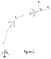
- Fig. 2 is a trajectory for flight during TA according to this invention.
- Fig.1 Three sets of coordinates have to be considered: the Global LLLN navigation system 11, the body axes system of the carrier airplane (not shown), and the Cartesian right hand coordinate set 12, which is computed by the INS of the carried vehicle according to its IMU data.
- the computed coordinate set of the carried vehicle is rotated with respect to the LLLN system by a yaw angle ⁇ about the D axis. with a pitch angle ⁇ about the E axis, and a roll angle ⁇ about the N axis.
- ⁇ (t) ( ⁇ N. ⁇ E , ⁇ D ), whose terms are the difference between the measured velocity components supplied by the INS of the carrier vehicle and the corresponding measured velocity components supplied by the INS of the carriedvehicle.
- ⁇ (t) which is time dependent, is based at each moment on the measurements of the IMUs in both vehicles adjusted by the value (at the same moment), of a computed state vector X (t).
- the computed state vector X (t) is a time dependent, 12x1 dimensional array, its terms representing the estimated error in the state of the carried vehicle with respect to that of carrier vehicle whose state serves as reference.
- the first six terms of X (t) are: The velocity error group ⁇ ( ⁇ N , ⁇ E , ⁇ D ), whose components in the LLLN north pointing coordinate system are shown in Fig. 1, and the attitude error group ⁇ which is defined with respect to these axes (N,E,D), whose members are the angle ⁇ , which is the rotation about the E axis, the angle ⁇ , which is the rotation about the N axis, and the angle ⁇ , which is the rotation about the D axis.
- ⁇ (t) A distinction should be made between the meaning of ⁇ (t) as a measured (noisy and fluctuating) vector, and the meaning of ⁇ as it appears in the state vector where it represents a predicted filtered estimate of the velocity error.
- the other components of X (t) are; ⁇ (x3), the gyroscopes' drifts, and ⁇ (x3), the accelerometers' biases.
- F(t) is the errors dynamic matrix whose nominal elements represent the propagation of the navigation errors, and ⁇ is a normal distributed, zero mean, white noise vector which represens the model uncertainty in F(t).
- ⁇ (t) is fed into the Kalman filter whose output is X (t);
- the obtained X (t) is used for the adjustment of the next set of measured ⁇ (t) values which in turn yield a new value of X (t) and vice versa.
- ⁇ (t) becomes sufficiently small and X (t) converges to a constant which provides the pre-launch initial conditions for the INS of the carried vehicle.
- X (t) is not updated and is allowed to change while the carried vehicle's INS navigates autonomously. This is followed by a relatively large adjustment step of X (t) at a later stage where the measurements are no longer sensitive to time delays.
- the method for TA of the present invention includes the following stages:
Landscapes
- Engineering & Computer Science (AREA)
- Radar, Positioning & Navigation (AREA)
- Remote Sensing (AREA)
- Automation & Control Theory (AREA)
- Physics & Mathematics (AREA)
- General Physics & Mathematics (AREA)
- Chemical & Material Sciences (AREA)
- Combustion & Propulsion (AREA)
- General Engineering & Computer Science (AREA)
- Navigation (AREA)
- Position Fixing By Use Of Radio Waves (AREA)
- Image Analysis (AREA)
- Traffic Control Systems (AREA)
Abstract
Description
- The present invention relates to in-flight transfer alignment of the inertial navigation system (INS) of a carried vehicle which is launched from a carrier vehicle and, in particularly to the alignment procedure in the presence of unknown delays in the measurements provided by the INS of the carrier vehicle, with respect to the measurements taken by the INS of the carried vehicle.
- Airplanes often carry with them other flying vehicles, such as unmanned airplanes or missiles, hereinafter; carried vehicles, which are to be launched during flight.
- Once the carried vehicle is launched, it will use its own internal measurement unit (IMU) to provide data to its autonomous INS. In order to do so correctly, the IMU of the carried vehicle has to be calibrated and aligned prior the launch.
- The calibaration and alignment is performed during flight, while the two vehicles are still attached. In this procedure, called flight transfer alignment, the velocity of the carried vehicle as computed by its INS according to the data supplied by its IMU, is compared to the velocity supplied by the aircraft's INS, which is regarded to be error free and is therefore used as reference.
- The difference between these two velocities which is attributed to the misalignment of the carried vehicle with respect to its carrier and to the offset of the gyroscopes and accelerometers of its IMU, is processed by a computerized statistical procedure known as a Kalman filter which yields the misalignment data of the carried vehicle with regard to its carrier as well as the carried IMU drift and bias data.
- This procedure, of aligning during flight of the carried vehicle's INS with the carrier's INS by comparing their velocities as supplied by the measurements of their independent IMUs, is known as transfer alignment (TA).
- While the estimation of the level misalignment angles (pitch, and roll, ), illustrated in Fig.1 to which reference is now made. is accomplished with no difficulties, the azimuth misalignment (yaw angle, ϕ) requires that the carrier vehicle perform alignment maneuvers which enable the Kalman filter TA to achieve obseravability of the yaw angle, and to separate between tilt errors and accelerometer biases, which otherwise tend to compensate each other.
- Generally, flight trajectory during the TA may include four flight segments: The first flight segment is a straight and level flight for the purpose of initial leveling. The second segment whose purpose is the azimuth alignment, consists of a trajectory which is C shaped in parallel to ground. The third segment, for the purpose of final leveling, is again a straight and level flight at the same direction as in the first segment, and the last section, sometimes omitted is used to simulate the navigation of the carried vehicle after the transfer alignment.
- It has been shown however, that the use of the information obtained during the second segment of the transfer alignment flight, which is essential for the estimation of the azimuth misallignment error, introduces a large position error.
- The reason for it as explained by Bar-Itzhak and Vitek ( I.Y.Bar-Itzhak and Y.Vitek, "The enigma of false Bias Detection in a Strapdown System During Transfer Alignment", J. Guidance, 8, 175 (1985) ), is a time delay between the data produced by the carrier's INS and the data of the carried vehicle's INS. which occurs because both systems operate with independent clocks which are not synchronized.
- It was further shown by Bar-Itzhak and Vitek that this undefined constant time delay, which was introduced into the measurements, resembles a signal, which only a longitudinal accelerometer bias would have made.
- Thus, the Kalman filter algorithm whose model is based on a dynamic system which does not model the influence of the time delay, identifies the signature of the time delay in the measured signal as the signature of the longitudinal accelerometer bias. Consequently the Kalmam filter produces an excessive estimate of the accelerometer bias.
- It is evident that such synchronization errors arise only during the second segment of the transfer alignment flight, where the data changes due the lateral acceleration in the flight maneuver, where as during the straight and level flight (in segments I and III), where the velocity readings of the INSs are constant, (except for white noise), no time delay effects exist.
- Because the trajectory of the second segment is required for the yaw-angle observability, and because the synchronization of the data during this segment requires an extra effort, it is desired to have a method for TA, which overcomes the uncertainties which are introduced by the time delay.
- We have comprehended the fact that synchronization errors affect TA only when the velocity measurements of the carrier and of the carried vehicle are compared while the aircraft is accelerating (during the second segment of the alignment flight). Furthermore, we are aware of the prior art, which considered flight in the second segment to be essential for a complete TA and required that velocity errors be measured during flight in this segment.
- We have discovered, that the important factor about TA is the fact that there exists a lateral acceleration and thus velocity changes between the first and the third segments, and that this information can be handled later, rather then collecting the data during the transition period.
- Accordingly, the present invention is a method of TA, which does not compare the velocities during the acceleration of the aircraft.
- The validity of our method was analytically proven and confirmed by simulations and actual flight tests.
- The present invention includes the definition of a 12 dimensional state vector, which consist of the estimations of the following carried vehicle's error components: velocities (x3), angles (x3), gyroscope drifts (x3) and accelerometer biases (x3).
- This vector which is the output of the Kalman filter, whose input is the measured difference between the carrier velocity and the carried vehicle velocity, (the velocity error vector), is continuously updated during the TA flight.
- The values of the terms of the state vector prior to the launch provides the pre-launch initial condition for the carried vehicle navigation during its mission; The conditions are: its initial velocities, its initial attitude with respect to the LLLN (Local Level Local North) coordinate system shown in Fig.1, and its initial instrumental offsets.
- The present invention includes a new schedule of the TA flight and a different routine for data processing, which are based on the possibility of separating the state vector entirely into its components, during all stages of the alignment flight.
- It is therefore an object of the present invention to provide a method for determining the pre-launch inertial condition for the INS of a carrier based launched vehicle.
- It is another object of the present invention to provide a new method of TA.
- It is another object of the present invention to provide such a method, which is not subjected to errors, which are caused by time delays in the information supplied by the carrier vehicle.
- It is another object of the present invention to provide such a method, in which the alignment maneuvers of the carrier airplane are minimized.
- It is another object of the present invention to provide such a method in cost effective manner.
- Other objects of the invention will become apparent upon reading the following description taken in conjunction with the accompanying drawings.
- It should also be understood that this invention is not limited to aircraft. and that it is applicable to boarding platforms of other kinds including space naval or under water vehicles.
- Fig.1 is a perspective view of the relation between the LLLN navigation coordinates and the coordinate system computed by the carried vehicle's INS, helpful in understanding the invention.
- Fig. 2 is a trajectory for flight during TA according to this invention.
- The preferred embodiments herein are not intended to be exhaustive and to limit in any way the scope of the invention, rather they are used as examples for the clarification of the invention and for the enabling of other skilled in the art to utilize its teaching.
- For a detailed description of the invention, reference is now made to Fig.1. Three sets of coordinates have to be considered: the Global LLLN
navigation system 11, the body axes system of the carrier airplane (not shown), and the Cartesian right hand coordinate set 12, which is computed by the INS of the carried vehicle according to its IMU data. - While the INS of the carrier platform handles satisfactorily the difference between the first two coordinate systems, uncertainties arise with respect to the alignment of the first and third coordinate systems. as a result, the computed coordinate set of the carried vehicle is rotated with respect to the LLLN system by a yaw angle ϕ about the D axis. with a pitch angle about the E axis, and a roll angle about the N axis.
- Consequently, the computed velocity of the carried vehicle in the LLLN navigation system as reported by its INS deviates from the velocity of the carrier vehicle.
- Another reason for this deviation. is due to the fact that the velocity as measured by the IMU of the carried carrier in its own system can be erroneous due to the carried gyro's drifts and accelerometer's biases which have not been yet corrected.
- Thus, a measurable velocity error vector in LLLN axes is defined,
ν (t) (νN.νE,νD), whose terms are the difference between the measured velocity components supplied by the INS of the carrier vehicle and the corresponding measured velocity components supplied by the INS of the carriedvehicle. -
ν (t) which is time dependent, is based at each moment on the measurements of the IMUs in both vehicles adjusted by the value (at the same moment), of a computed state vectorX (t). - The computed state vector
X (t) is a time dependent, 12x1 dimensional array, its terms representing the estimated error in the state of the carried vehicle with respect to that of carrier vehicle whose state serves as reference. The first six terms ofX (t) are: The velocity error group ν (νN, νE, νD), whose components in the LLLN north pointing coordinate system are shown in Fig. 1, and the attitude error group ψ which is defined with respect to these axes (N,E,D), whose members are the angle , which is the rotation about the E axis, the angle , which is the rotation about the N axis, and the angle ϕ, which is the rotation about the D axis.
A distinction should be made between the meaning ofν (t) as a measured (noisy and fluctuating) vector, and the meaning of ν as it appears in the state vector where it represents a predicted filtered estimate of the velocity error. The other components ofX (t) are; ε (x3), the gyroscopes' drifts, and ▿ (x3), the accelerometers' biases. The system model is that of a linear time variant system for which:
H(t) is the observation matrix: H(t) = [I3x3|03x3|03x3|03x3], and σ is a normal distributed, zero mean, white noise element. - During TA,
ν (t) is fed into the Kalman filter whose output isX (t); The obtainedX (t) is used for the adjustment of the next set of measuredν (t) values which in turn yield a new value ofX (t) and vice versa. - When TA is accomplished for a long enough time,
ν (t) becomes sufficiently small andX (t) converges to a constant which provides the pre-launch initial conditions for the INS of the carried vehicle. - It should be evident that a key factors in the TA procedure is the possibility for the correct estimation of the vector
X (t), and in particular, the correct computational allocation of error among its 12 terms. - In the terminology of the art, such property of the system is referred to as its "observability", and the main point to regard is that; unless it can be analytically proven that the system preserves its observability, the present method is unreliable.
- According to the prior art, (see e.g., Baziw.I, and Leondes C.T., "In-Flight Alignment and Calibration of IMU", Part I and II, IEEE Transactions on Aerospace and Electronic Systems, Vol.AES-5, July 1972,pp.439-465), in order to accomplish a complete TA, it is necessary to fly in a trajectory, which includes a lateral acceleration.
- As noted above, an error is introduced due to measurement delay at this stage. However we were the first to comprehend that the processing and adjustment of the state vector with Kalman filter need not be performed while accelerating. Instead, according to the present invention, during acceleration,
X (t) is not updated and is allowed to change while the carried vehicle's INS navigates autonomously. This is followed by a relatively large adjustment step ofX (t) at a later stage where the measurements are no longer sensitive to time delays. - The proof for the observability of the system under the present method is found in appendix A.
- Accordingly, the method for TA of the present invention includes the following stages:
- 1). Define a state vector
X (t) and a velocity error vectorν (t), as in prior art, which was described above. - 2). Define as in prior art, a dynamic error matrix F(t), and an observation matrix H(t).

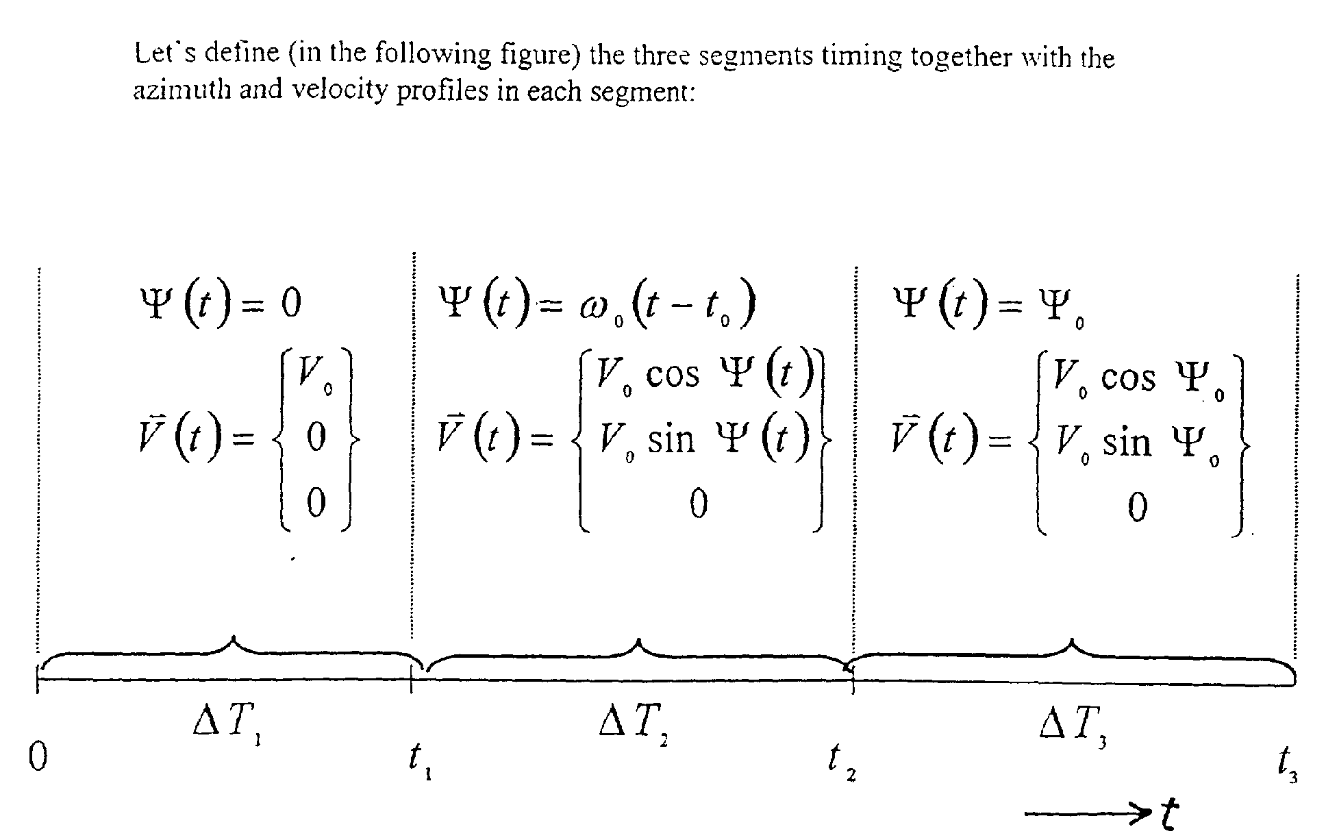
- 3). Define a three segment alignment trajectory, shown in Fig.2 as follows:
- Segment I, which consists of a straight and level flight at constant velocity Vo heading north.
- Segment II, which consists of a leveled turn at a constant angular rate ωo toward azimuth Ψo.
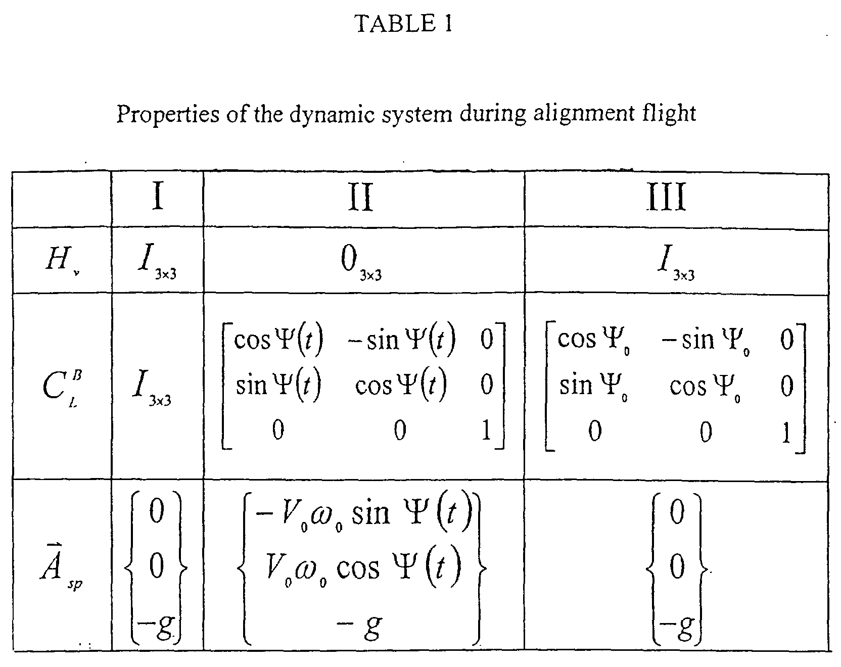
- Segment III, which consist of a straight and level flight at constant velocity Vo with heading angle Ψo. The properties of the dynamic system during the three segments are shown in TABLE 1.
- 4). Apply velocity match Kalman filter transfer alignment to the system, according to the
prior art method, with the exception that no updating of
X (t) is done during the flight in the second segment.




-
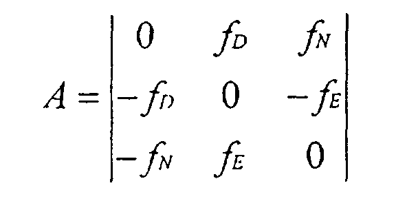
Instead of the complete skew symmetric matrix A,

Claims (9)
- A method for velocity match transfer alignment between a carrier vehicle and a carried vehicle comprising of:a) repeatedly measuring a velocity difference between the carrier vehicle and the carried vehicle;(b) subsequent to each said measurement, updating a state vector that include a predicted value of said velocity difference;(c) between said measurements, propagating said state vector forward in time; and(d) moving the carrier vehicle and the carried vehicle along a trajectory that includes a first segment, a second segment and a third segment, said moving along said first segment being effected at a first substantially constant velocity, said moving along second segment including an acceleration, said moving along said third segment being effected at a second substantially constant velocity different from said first velocity, said measuring, said updating, and said propagating being effected during said moving along said first and third segments, only said propagating being effected while moving along said second segment.
- A method according to claim 1 wherein, said state vector includes estimated attitude difference between the LLLN coordinate set and navigation axes as computed by said carried vehicle.
- A method according to claim 2 wherein, said state vector includes estimated instrumental offsets of the carried vehicle.
- A method according to claim 3 wherein, updating said state vector proceeds over time with a Kalman filter whose input is said measured velocity difference.
- A method according to claim 4 wherein, said moving in said first segment, and in said third segment is leveled .
- A method according to claim 5 wherein, said moving along said second segment is leveled.
- A method according to claim 6 wherein, said moving along said first segment is directed northwards.
- A method according to claim 7 wherein, said moving along said second segment is at constant angular velocity.
- A method according to claim 8 wherein, said moving along said third segment is in different direction then in said first segment.
Applications Claiming Priority (2)
| Application Number | Priority Date | Filing Date | Title |
|---|---|---|---|
| IL136566A IL136566A (en) | 2000-06-05 | 2000-06-05 | Method for transfer alignment of an inertial measurement unit in the presence of unknown aircraft measurements delays |
| IL13656600 | 2000-06-05 |
Publications (2)
| Publication Number | Publication Date |
|---|---|
| EP1162431A1 true EP1162431A1 (en) | 2001-12-12 |
| EP1162431B1 EP1162431B1 (en) | 2003-04-09 |
Family
ID=11074223
Family Applications (1)
| Application Number | Title | Priority Date | Filing Date |
|---|---|---|---|
| EP01112924A Expired - Lifetime EP1162431B1 (en) | 2000-06-05 | 2001-06-05 | Method for transfer alignment of an inertial measurement unit in the presence of unknown aircraft measurement delays |
Country Status (6)
| Country | Link |
|---|---|
| US (1) | US6556895B2 (en) |
| EP (1) | EP1162431B1 (en) |
| AT (1) | ATE237123T1 (en) |
| DE (1) | DE60100168T2 (en) |
| ES (1) | ES2194811T3 (en) |
| IL (1) | IL136566A (en) |
Cited By (3)
| Publication number | Priority date | Publication date | Assignee | Title |
|---|---|---|---|---|
| CN101634612B (en) * | 2009-08-21 | 2011-01-05 | 北京航空航天大学 | Method for determining long-endurance flight parameter of unmanned plane |
| EP2634534A3 (en) * | 2012-03-01 | 2014-03-26 | Honeywell International Inc. | Systems and methods to incorporate master navigation system resets during transfer alignment |
| CN104655132A (en) * | 2015-02-11 | 2015-05-27 | 北京航空航天大学 | Method for estimating body elastic deformation angle on basis of accelerometer |
Families Citing this family (8)
| Publication number | Priority date | Publication date | Assignee | Title |
|---|---|---|---|---|
| US7133776B2 (en) * | 2000-07-28 | 2006-11-07 | Litton Systems, Inc. | Attitude alignment of a slave inertial measurement system |
| FR2878954B1 (en) * | 2004-12-07 | 2007-03-30 | Sagem | HYBRID INERTIAL NAVIGATION SYSTEM BASED ON A CINEMATIC MODEL |
| US20070088496A1 (en) * | 2005-07-20 | 2007-04-19 | Atair Aerospace, Inc. | Automatic heading and reference system |
| CN106441301A (en) * | 2016-09-19 | 2017-02-22 | 北京机械设备研究所 | Air vehicle launching initial parameter acquiring method and system |
| CN106595711A (en) * | 2016-12-21 | 2017-04-26 | 东南大学 | Strapdown inertial navigation system coarse alignment method based on recursive quaternion |
| US11199410B2 (en) | 2019-04-30 | 2021-12-14 | Stmicroelectronics, Inc. | Dead reckoning by determining misalignment angle between movement direction and sensor heading direction |
| US11747142B2 (en) | 2019-04-30 | 2023-09-05 | Stmicroelectronics, Inc. | Inertial navigation system capable of dead reckoning in vehicles |
| CN112229271B (en) * | 2020-09-23 | 2022-08-30 | 郑州天一飞控机电有限公司 | Helicopter-mounted missile transfer alignment delay time estimation method |
Family Cites Families (8)
| Publication number | Priority date | Publication date | Assignee | Title |
|---|---|---|---|---|
| US4288049A (en) * | 1971-01-19 | 1981-09-08 | The United States Of America As Represented By The Secretary Of The Navy | Remote targeting system for guided missiles |
| US5245909A (en) * | 1990-05-07 | 1993-09-21 | Mcdonnell Douglas Corporation | Automatic sensor alignment |
| FR2668447B1 (en) * | 1990-10-29 | 1993-01-22 | Aerospatiale | SYSTEM FOR ALIGNING THE INERTIAL CONTROL UNIT OF A VEHICLE CARRYING ON THAT OF A CARRIER VEHICLE. |
| US5260709A (en) * | 1991-12-19 | 1993-11-09 | Hughes Aircraft Company | Autonomous precision weapon delivery using synthetic array radar |
| US5470033A (en) * | 1994-07-28 | 1995-11-28 | Tsai; Yeong-Shyeong | Method for controlling a carrier which is used to carry a flight vehicle |
| US5672872A (en) * | 1996-03-19 | 1997-09-30 | Hughes Electronics | FLIR boresight alignment |
| US6278945B1 (en) * | 1997-11-24 | 2001-08-21 | American Gnc Corporation | Fully-coupled positioning process and system thereof |
| US6094163A (en) * | 1998-01-21 | 2000-07-25 | Min-I James Chang | Ins alignment method using a doppler sensor and a GPS/HVINS |
-
2000
- 2000-06-05 IL IL136566A patent/IL136566A/en not_active IP Right Cessation
-
2001
- 2001-06-04 US US09/871,679 patent/US6556895B2/en not_active Expired - Fee Related
- 2001-06-05 DE DE60100168T patent/DE60100168T2/en not_active Expired - Fee Related
- 2001-06-05 ES ES01112924T patent/ES2194811T3/en not_active Expired - Lifetime
- 2001-06-05 EP EP01112924A patent/EP1162431B1/en not_active Expired - Lifetime
- 2001-06-05 AT AT01112924T patent/ATE237123T1/en not_active IP Right Cessation
Non-Patent Citations (2)
| Title |
|---|
| BAR-ITZHACK I Y ET AL: "The enigma of false bias detection in a strapdown system during transfer alignment", JOURNAL OF GUIDANCE, CONTROL, AND DYNAMICS, MARCH-APRIL 1985, USA, vol. 8, no. 2, pages 175 - 180, XP001016052, ISSN: 0731-5090 * |
| BAZIW J ET AL: "In-flight alignment and calibration of inertial measurement units. II. Experimental results", IEEE TRANSACTIONS ON AEROSPACE AND ELECTRONIC SYSTEMS, JULY 1972, USA, vol. AES-8, no. 4, pages 450 - 465, XP001016056, ISSN: 0018-9251 * |
Cited By (4)
| Publication number | Priority date | Publication date | Assignee | Title |
|---|---|---|---|---|
| CN101634612B (en) * | 2009-08-21 | 2011-01-05 | 北京航空航天大学 | Method for determining long-endurance flight parameter of unmanned plane |
| EP2634534A3 (en) * | 2012-03-01 | 2014-03-26 | Honeywell International Inc. | Systems and methods to incorporate master navigation system resets during transfer alignment |
| CN104655132A (en) * | 2015-02-11 | 2015-05-27 | 北京航空航天大学 | Method for estimating body elastic deformation angle on basis of accelerometer |
| CN104655132B (en) * | 2015-02-11 | 2017-08-25 | 北京航空航天大学 | A kind of body elastic deformation angular estimation method based on accelerometer |
Also Published As
| Publication number | Publication date |
|---|---|
| IL136566A (en) | 2007-07-24 |
| EP1162431B1 (en) | 2003-04-09 |
| US6556895B2 (en) | 2003-04-29 |
| DE60100168T2 (en) | 2004-02-26 |
| US20020049519A1 (en) | 2002-04-25 |
| IL136566A0 (en) | 2003-06-24 |
| ES2194811T3 (en) | 2003-12-01 |
| DE60100168D1 (en) | 2003-05-15 |
| ATE237123T1 (en) | 2003-04-15 |
Similar Documents
| Publication | Publication Date | Title |
|---|---|---|
| US7979231B2 (en) | Method and system for estimation of inertial sensor errors in remote inertial measurement unit | |
| US7328104B2 (en) | Systems and methods for improved inertial navigation | |
| CN105910602B (en) | A kind of Combinated navigation method | |
| EP1862763A2 (en) | Rapid self-alignment of a strapdown inertial system through real-time reprocessing | |
| US6094163A (en) | Ins alignment method using a doppler sensor and a GPS/HVINS | |
| US7957899B2 (en) | Method for determining the attitude, position, and velocity of a mobile device | |
| CN110132267B (en) | Optical fiber inertial navigation system of air-space-ground integrated aircraft and optical fiber inertial navigation on-orbit alignment method | |
| US20040030464A1 (en) | Attitude alignment of a slave inertial measurement system | |
| US20100179758A1 (en) | Aircraft navigation using the global positioning system and an attitude and heading reference system | |
| EP1162431B1 (en) | Method for transfer alignment of an inertial measurement unit in the presence of unknown aircraft measurement delays | |
| CN108534783A (en) | A kind of aircraft navigation method based on Beidou navigation technology | |
| GB2444814A (en) | Estimating inertial acceleration bias errors | |
| CN111220182B (en) | Rocket transfer alignment method and system | |
| Avrutov et al. | Gyrocompassing mode of the attitude and heading reference system | |
| CN114061575A (en) | Missile attitude angle fine alignment method and system under condition of large misalignment angle | |
| Groves et al. | Robust rapid transfer alignment with an INS/GPS reference | |
| CN107764268B (en) | Method and device for transfer alignment of airborne distributed POS (point of sale) | |
| Robins | Recent Developments in the" TERPROM" Integrated Navigation System | |
| EP3662343B1 (en) | In-flight azimuth determination | |
| Xiangming et al. | Gyrocompassing mode of the strapdown inertial navigation system | |
| US20250389537A1 (en) | Computer-implemented methods for attitude determination of an aircraft for navigation | |
| Özgeneci et al. | A Rapid Transfer Alignment Method with Unknown Measurement Time Delay | |
| RU2776856C2 (en) | Methods for determining the values of orientation angles during the movement of the aircraft and correcting the values of orientation angles | |
| Neusypin et al. | Algorithmic Methods for Correcting Aircraft Astro-Inertial Systems | |
| CN112179378A (en) | A Polarized Light Navigation Aided Transfer Alignment System |
Legal Events
| Date | Code | Title | Description |
|---|---|---|---|
| PUAI | Public reference made under article 153(3) epc to a published international application that has entered the european phase |
Free format text: ORIGINAL CODE: 0009012 |
|
| AK | Designated contracting states |
Kind code of ref document: A1 Designated state(s): AT BE CH CY DE DK ES FI FR GB GR IE IT LI LU MC NL PT SE TR |
|
| AX | Request for extension of the european patent |
Free format text: AL;LT;LV;MK;RO;SI |
|
| 17P | Request for examination filed |
Effective date: 20020212 |
|
| GRAG | Despatch of communication of intention to grant |
Free format text: ORIGINAL CODE: EPIDOS AGRA |
|
| 17Q | First examination report despatched |
Effective date: 20020628 |
|
| AKX | Designation fees paid |
Free format text: AT BE CH CY DE DK ES FI FR GB GR IE IT LI LU MC NL PT SE TR |
|
| GRAG | Despatch of communication of intention to grant |
Free format text: ORIGINAL CODE: EPIDOS AGRA |
|
| GRAH | Despatch of communication of intention to grant a patent |
Free format text: ORIGINAL CODE: EPIDOS IGRA |
|
| GRAH | Despatch of communication of intention to grant a patent |
Free format text: ORIGINAL CODE: EPIDOS IGRA |
|
| GRAA | (expected) grant |
Free format text: ORIGINAL CODE: 0009210 |
|
| AK | Designated contracting states |
Designated state(s): AT BE CH CY DE DK ES FI FR GB GR IE IT LI LU MC NL PT SE TR |
|
| PG25 | Lapsed in a contracting state [announced via postgrant information from national office to epo] |
Ref country code: AT Free format text: LAPSE BECAUSE OF FAILURE TO SUBMIT A TRANSLATION OF THE DESCRIPTION OR TO PAY THE FEE WITHIN THE PRESCRIBED TIME-LIMIT Effective date: 20030409 Ref country code: TR Free format text: LAPSE BECAUSE OF FAILURE TO SUBMIT A TRANSLATION OF THE DESCRIPTION OR TO PAY THE FEE WITHIN THE PRESCRIBED TIME-LIMIT Effective date: 20030409 Ref country code: FI Free format text: LAPSE BECAUSE OF FAILURE TO SUBMIT A TRANSLATION OF THE DESCRIPTION OR TO PAY THE FEE WITHIN THE PRESCRIBED TIME-LIMIT Effective date: 20030409 Ref country code: LI Free format text: LAPSE BECAUSE OF FAILURE TO SUBMIT A TRANSLATION OF THE DESCRIPTION OR TO PAY THE FEE WITHIN THE PRESCRIBED TIME-LIMIT Effective date: 20030409 Ref country code: CH Free format text: LAPSE BECAUSE OF FAILURE TO SUBMIT A TRANSLATION OF THE DESCRIPTION OR TO PAY THE FEE WITHIN THE PRESCRIBED TIME-LIMIT Effective date: 20030409 Ref country code: BE Free format text: LAPSE BECAUSE OF FAILURE TO SUBMIT A TRANSLATION OF THE DESCRIPTION OR TO PAY THE FEE WITHIN THE PRESCRIBED TIME-LIMIT Effective date: 20030409 |
|
| REG | Reference to a national code |
Ref country code: GB Ref legal event code: FG4D |
|
| REG | Reference to a national code |
Ref country code: CH Ref legal event code: EP |
|
| REG | Reference to a national code |
Ref country code: IE Ref legal event code: FG4D |
|
| PG25 | Lapsed in a contracting state [announced via postgrant information from national office to epo] |
Ref country code: CY Free format text: LAPSE BECAUSE OF FAILURE TO SUBMIT A TRANSLATION OF THE DESCRIPTION OR TO PAY THE FEE WITHIN THE PRESCRIBED TIME-LIMIT Effective date: 20030605 Ref country code: LU Free format text: LAPSE BECAUSE OF NON-PAYMENT OF DUE FEES Effective date: 20030605 Ref country code: IE Free format text: LAPSE BECAUSE OF NON-PAYMENT OF DUE FEES Effective date: 20030605 |
|
| PG25 | Lapsed in a contracting state [announced via postgrant information from national office to epo] |
Ref country code: MC Free format text: LAPSE BECAUSE OF NON-PAYMENT OF DUE FEES Effective date: 20030630 |
|
| PG25 | Lapsed in a contracting state [announced via postgrant information from national office to epo] |
Ref country code: GR Free format text: LAPSE BECAUSE OF FAILURE TO SUBMIT A TRANSLATION OF THE DESCRIPTION OR TO PAY THE FEE WITHIN THE PRESCRIBED TIME-LIMIT Effective date: 20030709 Ref country code: PT Free format text: LAPSE BECAUSE OF FAILURE TO SUBMIT A TRANSLATION OF THE DESCRIPTION OR TO PAY THE FEE WITHIN THE PRESCRIBED TIME-LIMIT Effective date: 20030709 Ref country code: DK Free format text: LAPSE BECAUSE OF FAILURE TO SUBMIT A TRANSLATION OF THE DESCRIPTION OR TO PAY THE FEE WITHIN THE PRESCRIBED TIME-LIMIT Effective date: 20030709 |
|
| REG | Reference to a national code |
Ref country code: SE Ref legal event code: TRGR |
|
| REG | Reference to a national code |
Ref country code: CH Ref legal event code: PL |
|
| ET | Fr: translation filed | ||
| PLBE | No opposition filed within time limit |
Free format text: ORIGINAL CODE: 0009261 |
|
| STAA | Information on the status of an ep patent application or granted ep patent |
Free format text: STATUS: NO OPPOSITION FILED WITHIN TIME LIMIT |
|
| 26N | No opposition filed |
Effective date: 20040112 |
|
| REG | Reference to a national code |
Ref country code: IE Ref legal event code: MM4A |
|
| PGFP | Annual fee paid to national office [announced via postgrant information from national office to epo] |
Ref country code: IT Payment date: 20060630 Year of fee payment: 6 |
|
| PGFP | Annual fee paid to national office [announced via postgrant information from national office to epo] |
Ref country code: DE Payment date: 20070629 Year of fee payment: 7 |
|
| PGFP | Annual fee paid to national office [announced via postgrant information from national office to epo] |
Ref country code: ES Payment date: 20070725 Year of fee payment: 7 |
|
| PGFP | Annual fee paid to national office [announced via postgrant information from national office to epo] |
Ref country code: GB Payment date: 20070730 Year of fee payment: 7 |
|
| PGFP | Annual fee paid to national office [announced via postgrant information from national office to epo] |
Ref country code: NL Payment date: 20070717 Year of fee payment: 7 Ref country code: SE Payment date: 20070724 Year of fee payment: 7 |
|
| PGFP | Annual fee paid to national office [announced via postgrant information from national office to epo] |
Ref country code: FR Payment date: 20070718 Year of fee payment: 7 |
|
| EUG | Se: european patent has lapsed | ||
| GBPC | Gb: european patent ceased through non-payment of renewal fee |
Effective date: 20080605 |
|
| NLV4 | Nl: lapsed or anulled due to non-payment of the annual fee |
Effective date: 20090101 |
|
| REG | Reference to a national code |
Ref country code: FR Ref legal event code: ST Effective date: 20090228 |
|
| PG25 | Lapsed in a contracting state [announced via postgrant information from national office to epo] |
Ref country code: DE Free format text: LAPSE BECAUSE OF NON-PAYMENT OF DUE FEES Effective date: 20090101 |
|
| PG25 | Lapsed in a contracting state [announced via postgrant information from national office to epo] |
Ref country code: NL Free format text: LAPSE BECAUSE OF NON-PAYMENT OF DUE FEES Effective date: 20090101 |
|
| PG25 | Lapsed in a contracting state [announced via postgrant information from national office to epo] |
Ref country code: GB Free format text: LAPSE BECAUSE OF NON-PAYMENT OF DUE FEES Effective date: 20080605 |
|
| REG | Reference to a national code |
Ref country code: ES Ref legal event code: FD2A Effective date: 20080606 |
|
| PG25 | Lapsed in a contracting state [announced via postgrant information from national office to epo] |
Ref country code: FR Free format text: LAPSE BECAUSE OF NON-PAYMENT OF DUE FEES Effective date: 20080630 |
|
| PG25 | Lapsed in a contracting state [announced via postgrant information from national office to epo] |
Ref country code: IT Free format text: LAPSE BECAUSE OF NON-PAYMENT OF DUE FEES Effective date: 20070605 |
|
| PG25 | Lapsed in a contracting state [announced via postgrant information from national office to epo] |
Ref country code: ES Free format text: LAPSE BECAUSE OF NON-PAYMENT OF DUE FEES Effective date: 20080606 |
|
| PG25 | Lapsed in a contracting state [announced via postgrant information from national office to epo] |
Ref country code: SE Free format text: LAPSE BECAUSE OF NON-PAYMENT OF DUE FEES Effective date: 20080606 |