EP1162346A2 - Cooling for turbine shroud segments - Google Patents
Cooling for turbine shroud segments Download PDFInfo
- Publication number
- EP1162346A2 EP1162346A2 EP01303095A EP01303095A EP1162346A2 EP 1162346 A2 EP1162346 A2 EP 1162346A2 EP 01303095 A EP01303095 A EP 01303095A EP 01303095 A EP01303095 A EP 01303095A EP 1162346 A2 EP1162346 A2 EP 1162346A2
- Authority
- EP
- European Patent Office
- Prior art keywords
- slot
- side panels
- bottom wall
- lower slot
- spaced
- Prior art date
- Legal status (The legal status is an assumption and is not a legal conclusion. Google has not performed a legal analysis and makes no representation as to the accuracy of the status listed.)
- Granted
Links
Images


Classifications
-
- F—MECHANICAL ENGINEERING; LIGHTING; HEATING; WEAPONS; BLASTING
- F01—MACHINES OR ENGINES IN GENERAL; ENGINE PLANTS IN GENERAL; STEAM ENGINES
- F01D—NON-POSITIVE DISPLACEMENT MACHINES OR ENGINES, e.g. STEAM TURBINES
- F01D11/00—Preventing or minimising internal leakage of working-fluid, e.g. between stages
- F01D11/005—Sealing means between non relatively rotating elements
-
- F—MECHANICAL ENGINEERING; LIGHTING; HEATING; WEAPONS; BLASTING
- F01—MACHINES OR ENGINES IN GENERAL; ENGINE PLANTS IN GENERAL; STEAM ENGINES
- F01D—NON-POSITIVE DISPLACEMENT MACHINES OR ENGINES, e.g. STEAM TURBINES
- F01D25/00—Component parts, details, or accessories, not provided for in, or of interest apart from, other groups
- F01D25/24—Casings; Casing parts, e.g. diaphragms, casing fastenings
- F01D25/246—Fastening of diaphragms or stator-rings
-
- F—MECHANICAL ENGINEERING; LIGHTING; HEATING; WEAPONS; BLASTING
- F02—COMBUSTION ENGINES; HOT-GAS OR COMBUSTION-PRODUCT ENGINE PLANTS
- F02C—GAS-TURBINE PLANTS; AIR INTAKES FOR JET-PROPULSION PLANTS; CONTROLLING FUEL SUPPLY IN AIR-BREATHING JET-PROPULSION PLANTS
- F02C7/00—Features, components parts, details or accessories, not provided for in, or of interest apart form groups F02C1/00 - F02C6/00; Air intakes for jet-propulsion plants
- F02C7/28—Arrangement of seals
-
- F—MECHANICAL ENGINEERING; LIGHTING; HEATING; WEAPONS; BLASTING
- F05—INDEXING SCHEMES RELATING TO ENGINES OR PUMPS IN VARIOUS SUBCLASSES OF CLASSES F01-F04
- F05D—INDEXING SCHEME FOR ASPECTS RELATING TO NON-POSITIVE-DISPLACEMENT MACHINES OR ENGINES, GAS-TURBINES OR JET-PROPULSION PLANTS
- F05D2240/00—Components
- F05D2240/10—Stators
- F05D2240/11—Shroud seal segments
-
- F—MECHANICAL ENGINEERING; LIGHTING; HEATING; WEAPONS; BLASTING
- F05—INDEXING SCHEMES RELATING TO ENGINES OR PUMPS IN VARIOUS SUBCLASSES OF CLASSES F01-F04
- F05D—INDEXING SCHEME FOR ASPECTS RELATING TO NON-POSITIVE-DISPLACEMENT MACHINES OR ENGINES, GAS-TURBINES OR JET-PROPULSION PLANTS
- F05D2260/00—Function
- F05D2260/20—Heat transfer, e.g. cooling
- F05D2260/202—Heat transfer, e.g. cooling by film cooling
Definitions
- the present invention relates generally to a gas turbine engine cooling component for end rail cooling, and in particular a turbine engine shroud where each shroud segment provides cooling to both the high pressure and low pressure turbine sections of a gas turbine engine.
- the present invention further relates to a turbine engine subassembly, and in particular a shroud subassembly that uses a pair of such cooling segments in combination with at least one discourager and primary spline seal.
- a particularly important component subjected to extremely high temperatures is the shroud located immediately downstream of the high pressure turbine nozzle, immediately downstream from the combustor.
- the shroud closely surrounds the rotor of the high pressure turbine and thus defines the outer boundary (flow path) of the extremely high temperature main (hot) gas stream flowing through the high pressure turbine.
- adequate shroud cooling is an important concern.
- Shroud cooling can be achieved by impingement cooling of the back surface of the shroud, as well as cooling holes that extend from the back surface of the base of the shroud and through to the forward or leading edge of the shroud, the bottom or inner surface of the base in contact with the main (hot) gas stream, and the aft or trailing edge of the shroud to provide both convection cooling inside the holes, as well as impingement and film cooling of the shroud. Cooling flow is also provided through the side panels or rails as convection cooling inside the cooling passages or holes, as well as impingement cooling as cooling air exits from the holes. See, for example, commonly assigned U.S.
- Patent 5,169,287 (Proctor et al), issued December 8, 1992, which shows a prior embodiment of shroud cooling of the high pressure turbine section of a gas turbine engine. This cooling minimizes local oxidation and burning of the shrouds near the hot main or core gas stream in the high pressure turbine section. Indeed, the cooling holes that exit through the side panel of the shroud of commonly assigned U.S. Patent 5,169,287 can provide important impingement cooling to the side panel of the adjacent shroud.
- the leading edge of the shroud is subject to the hottest flow path gas or air, and has the highest heat transfer coefficient, making this section one of the most difficult to cool.
- a circumferential row of holes can be angled to also exit at the leading edge of the shroud to provide both convection and film cooling at the leading edge of the shroud. As this cooling film decays and mixes with the hot flow path air, additional circumferential rows of cooling holes can be required to provide more convection and film cooling.
- the shroud assembly shown in commonly assigned U.S. Patent 5,127,793 extends from approximately the aft end of the upstream turbine nozzle to approximately the leading edge of the downstream turbine nozzle and encloses (i.e., provides a 360° annular structure around) the outer air flow path of a gas turbine engine that typically has a turning nozzle to direct the air flow properly into the blade row, then into a row of blades in the HPT section, and then into another row of blades in the LPT section.
- Axial gaps between these shroud segments allow for thermal growth over the large range of temperatures the gas turbine engine produces.
- As hot flow path air passes through the row of turbine blades work is extracted from the air, thus creating a pressure and temperature drop axially through the blade row.
- both the pressure and temperature is higher at the leading edge of the shroud and lower at the trailing edge of the shroud.
- a typical sealing method along the axial split lines or gaps between shroud segments is to provide a machined groove or slot in which a thin metal seal (usually referred to as a "spline seal") is placed, with pressure loading across the seal to provide positive sealing and to minimize air leakage.
- a thin metal seal usually referred to as a "spline seal”
- FIG 11a of commonly assigned U.S. Patent 5,127,793 which shows a pair of longitudinally extending slots in shroud segment 30, the lower slot receiving the lower or “discourager” spline seal, the upper slot(s) receiving the upper or “primary” spline seal(s).
- the portion of the axial segment gap that is set up between the shroud segments below the "discourager” seal also has hot flow path air traveling axially down it due to the pressure gradient produced by the turbine blade row.
- no preferential cooling is added to this "trench.”
- air that leaks around the "discourager” seal and the conduction from adjacent metal has been deemed sufficient to cool the axial split lines, i.e., at the side rails or panels of the shroud segments.
- oxidation and loss (melting) of the parent material along the axial split-lines of shroud segments can occur.
- the present invention relates to a turbine engine cooling component such as a shroud segment for a combined high pressure and low pressure turbine section of a gas turbine engine that provides effective end rail cooling to the side rails or panels of adjacent turbine cooling components (e.g., at the axial split lines between adjacent shroud segments), as well as effective cooling in the gap or "trench" between adjacent turbine engine cooling components (e.g., adjacent shroud segments) that is below the discourager spline seal.
- a turbine engine cooling component such as a shroud segment for a combined high pressure and low pressure turbine section of a gas turbine engine that provides effective end rail cooling to the side rails or panels of adjacent turbine cooling components (e.g., at the axial split lines between adjacent shroud segments), as well as effective cooling in the gap or "trench” between adjacent turbine engine cooling components (e.g., adjacent shroud segments) that is below the discourager spline seal.
- This turbine cooling component comprises: (a) a circumferential leading edge; (b) a circumferential trailing edge spaced from the leading edge; (c) an arcuate base connected to the trailing and leading edges and having a back surface and an arcuate inner surface that is in contact with the main (hot) gas stream of the gas turbine engine moving in the direction from the leading edge to the trailing edge of the turbine component; (d) a pair of spaced opposed axial side panels connected to the leading and trailing edges; (e) each of the side panels having a lower discourager spline seal slot extending longitudinally from the leading edge to the trailing edge of each side panel that is capable of receiving an edge of a discourager spline seal, each lower slot having at least a bottom wall and a top wall; (f) each of the side panels having an upper primary spline seal slot spaced above the lower slot and extending longitudinally from the leading edge to the trailing edge of each side panel that is capable of receiving an edge of a primary spline seal, each upper
- the present invention further relates to a turbine engine cooling subassembly comprising a pair of such adjacent turbine engine components, and having: (1) opposed adjacent side panels having a gap therebetween and wherein the spacing of the air flow pathways along the length of the lower slot for each of the adjacent side panels is staggered such that the outlet of each of the cooling air passages exiting each adjacent side panel are opposite one of the air flow pathways of the other adjacent side panel; (2) at least one discourager spline seal positioned in the gap between the opposed adjacent side panels and including a pair of spaced edges having a length and thickness such that each of the edges is capable of being received by the lower slot of one of the adjacent side panels; (3) the at least one discourager seal being positioned below the outlet of each of the cooling air passages exiting each adjacent side panel; (4) at least one primary spline seal positioned in the gap and including a pair of spaced edges having a length and thickness such that each of the edges is capable of being received by the upper slot of one of the adjacent side panels.
- the turbine engine cooling component (e.g., shroud) of the present invention is particularly useful in providing effective, efficient and more uniform cooling to the end rail (i.e., split line) region, especially for the metal of the turbine component below the discourager seal.
- the turbine engine cooling subassembly (e.g., shroud cooling subassembly) of the present invention that comprises a pair of such turbine components (e.g., shroud segments) that have staggered or offset air flow pathways (preferably spaced recesses in the bottom wall of the lower slot) and outlets for the cooling air passages exiting from the adjacent side panels, also provide impingement cooling coverage to each of the adjacent side panels.
- this turbine cooling subassembly causes cooling air to flow: (a) over the discourager seal and then under it (via the air flow pathways such as the recesses in the bottom wall of the lower slot) to impinge on the side panel (below the lower slot) of the turbine component (e.g., shroud) from which the cooling air came from; (b) downstream above the discourager seal (via the air flow pathways) and out, such as through recesses in the bottom of wall the lower slot of same side panel from which the cooling air came to impinge on the adjacent side panel (below its lower slot); and (c) to purge the hot gas or air in the "trench" below the discourager seal.
- the turbine engine cooling component of the present invention can also have certain optional but preferred features.
- One preferred feature is to have no cooling air passages exiting from certain portions of the side panel where cooling air flow is not required or is unnecessary, and thus economizes the usage of the total cooling air flow.
- Yet another preferred feature is to provide a sub-impingement pocket at the rear or aft portion of certain sections of the turbine cooling component, especially a shroud cooling segment having a high pressure turbine (HPT) section.
- HPT high pressure turbine
- This sub-impingement pocket helps reduce the source pressure of the cooling air provided to the rear or aft portion of the HPT section (which is usually at its lowest sink pressure in the HPT section) to provide an adequate amount of cooling air to the cooling air passages exiting from the side panel at the rear or aft portion of the HPT section and to reduce the total air flow emitting from such passages, again economizing the usage of the total cooling air flow.
- FIG. 1 shows an embodiment of the turbine engine cooling assembly of the present invention in the form of a shroud assembly, generally indicated as 110 for the high pressure and low pressure turbine sections of a gas turbine engine.
- the turbine engine cooling assembly of the present invention can also be suitable for providing cooling to other sections in the gas turbine engine such as the nozzle and/or vane sections.
- the shroud assembly of the present invention comprises turbine engine cooling components in the form of shroud segments indicated as 130 which can be either one-piece or two-piece.
- Shroud segment 130 is provided with a forward mounting hook 132 at the circumferential leading edge thereof.
- Shroud segment 130 also has a central or mid mounting hook 134 and an aft or rear mounting hook 136 at the circumferential trailing edge of shroud segment 130.
- a number of shroud segments 130 are arranged circumferentially in a generally known fashion to form a segmented 360° shroud.
- a number of segmented shroud support structures 144 are used to interconnect the shroud segments 130.
- Each segmented support 144 circumferentially spans and typically supports two shroud segments 130, but could be appropriately modified to support one, three or more segments 130.
- Each segmented shroud support 144 is provided with a forward section 146, a central or mid-section 148 and an aft or rear section 150 that each respectively have forwardly projecting hangers 152, 154 and 156.
- Support structure 144 supports the respective shroud segments 130 as a result of mounting hooks 132, 134 and 136 being received, respectively, by hangers 152, 154 and 156, to provide tongue-in-groove interconnections (hook-in-hanger).
- Each shroud support structure 144 is further supported by a one-piece, continuous 360° annular shroud ring structure 158.
- the radial position of each shroud support 144, as well as each shroud segment 130, is closely controlled by three distinct 360° position control rings 160, 162, and 164 provided on ring structure 158.
- the front and mid-position control rings 160 and 162 are respectively formed with axially forwardly projecting hangers 166 and 170 that receive, respectively rearwardly projecting mounting hooks 168 and 172 of sections 146 and 148 of support structure 144, while the rear position control ring 164 is formed with an axially forwardly projecting hanger 174 that receives rearwardly projecting mounting hook 176 of section 150 of support structure 144, to provide circumferential tongue-in-groove interconnections (hook-in-hanger).
- each hanger 166, 170 and 174 on the support ring 158 is usually in direct axial alignment (i.e., aligned in the same radial plane) with its respective position control ring 160, 162 and 164.
- This alignment increases the rigidity of the entire shroud support assembly.
- the support ring structure 158 is typically bolted into the combustor case (not shown) at its aft end.
- the entire shroud support assembly is cantilevered off its forward end at the combustor case interface.
- the forward and mid-position control rings which are several inches away from the combustor aft flange, are thereby divorced from any non-uniform circumferential variations in radial deflection in the combustor case.
- the segmented shroud design is typically required to accommodate the thermal growth imposed by the hostile environment created by the hot flowing exhaust gas.
- the segmented shroud hangers effectively cut the heat conduction path between the high temperature shroud mounting hooks and the position control rings.
- the position control rings are thus well isolated from the hostile and non-uniform flow path environment.
- a portion of high pressure cooling air extracted from the compressor (not shown) is fed through high pressure turbine section feed hole(s) 177 in boss 178 of support 144. This portion of cooling air then impinges upon pan-shaped high pressure turbine section impingement baffle 179 (attached to support 144), thus creating the upper high pressure (HP) turbine section's HP pre-impingement cavity or plenum 180. This portion of high pressure air is then feed through an array of perforations 182 in baffle 179 as cooling air into the lower HP post-impingement cavity or plenum 184 of the high pressure turbine section of shroud segment 130. Compressor cooling air is also fed through low pressure turbine feed hole(s) 185 in support 144.
- each shroud segment 130 has a forward high pressure turbine (HPT) section 190 that includes the forward mounting hook 132 at the leading edge and forward end of the shroud segment, and a rear or aft low pressure turbine (LPT) section 192 that includes aft mounting hook 136 at the trailing edge and aft end of the shroud segment.
- HPT high pressure turbine
- LPT low pressure turbine
- the aft end of HPT section 190 and the forward end of LPT section 192 of shroud segment 130 are joined at the central or mid-mounting hook 134 and are adjacent to, respectively, the blades of the high pressure turbine and the blades of the low pressure turbine.
- HPT section 190 and LPT section 192 can be separate pieces joined or combined together by suitable means known in the art.
- the shroud segment 130 has a base 196 that extends from forward mounting hooking 132 to aft mounting hook 136.
- Base 196 has an outer or back surface, portions of which are indicated as 200 in the HPT section and 204 in the LPT section.
- Base 196 also has an inner surface 208 that is contact with the main (hot) gas stream indicated by arrow 210 that generally moves downstream in the direction from the leading to the trailing end of the shroud segment 130. As shown in FIG. 2, inner surface 208 extends generally straight from the forward end to the aft end of the HPT section 190, but then extends diagonally upward at the forward end of the LPT section 192 to about the midpoint thereof and then extends generally straight thereafter to the aft end of the LPT section.
- the shroud segment also has a pair of opposed spaced side rails or panels 214 that are connected at their leading and trailing ends by mounting hooks 132 and 136, as well at their central or mid-sections by mounting hook 134 and at their bottom edges by base 196.
- HPT section 190 has a plurality of spaced longitudinal ribs 218 that are connected at their respective ends by mounting hooks 132 and 134 and at their bottom edges by base 196.
- a laterally extending rib 222 is connected at its respective ends by side panels 214, and at the bottom edge by base 196 and divides the HP post-impingement cavity 184 (framed by mounting hooks 132 and 134, side panels 214 and base 196) into a forward higher pressure HP post-impingement pocket indicated as 226 and an aft lower pressure HP post sub-impingement pocket indicated as 230.
- the aft HP sub-impingement pocket 230 is fed cooling air through perforations in a secondary impingement baffle (not shown) located on top of the circumferential ribs 222 and extending aft to the mid-mounting hook 134 with its edges extending between the two respective side panels 214, this secondary impingement baffle also being fed cooling air from the HP post-impingement cavity 184.
- a secondary impingement baffle (not shown) located on top of the circumferential ribs 222 and extending aft to the mid-mounting hook 134 with its edges extending between the two respective side panels 214, this secondary impingement baffle also being fed cooling air from the HP post-impingement cavity 184.
- LPT section 192 also has a plurality of spaced longitudinal ribs 234 that are connected at their respective ends by mounting hooks 134 and 136 and at their bottom edges by base 196, as well as LP post-impingement cavity 189 (framed by mounting hooks 134 and 136, side panels 214 and base 196) that receives the cooling air fed through the perforations 188 in baffle 186.
- each of the side panels 214 have a lower or discourager seal groove or slot 242 and an upper or primary seal groove or slot 246 spaced above lower slot 242.
- Slots 242 and 246 each extend generally longitudinally from the leading edge or forward end of shroud segment 130 and terminate at about the trailing edge or aft end for lower slot 242 and at the aft end of the lower pressure impingement cavity for upper slot 246.
- slots 242 and 246 are shown as being continuous, these slots can also be in separate segments or sections, such as, example, in two separate sections, one for the HPT section, the other for the LPT section, or three separate sections where the LPT section has two separate sections for each slot, one being in the diagonal portion of the LPT section, the other being in the straight portion of the LPT section.
- FIGs. 2 and 3 Also shown in FIGs. 2 and 3 are a forward vertical seal groove or slot 248 at mounting hook 132, a central or mid-position vertical seal groove or slot 250 at mounting hook 134, and an aft vertical seal groove or slot 252 at mounting hook 136.
- Each of the vertical slots 248, 250 and 252 originate at or near inner surface 208 of base 196 and extend upwardly to perpendicularly intersect lower and upper slots 242 and 246 and terminate at the upper end of the respective mounting hooks 132, 134 and 136.
- lower slot 242 has a bottom wall 256, a side wall 260 connected at an edge to bottom wall 256 and a top wall 264 connected at an edge to side wall 260, while upper slot 246 has a bottom wall 266, a side wall 270 connected at an edge to bottom wall 266 and a top wall 274 connected at an edge to side wall 270.
- bottom wall 256 of lower slot 242 has a plurality of spaced alternating lands 278 and slots or recesses 282. While the lands 278 and recesses 282 are shown as having similar sizes and a square configuration, different sizes, as well as other shapes and configurations (such as rounded edges) can also be suitable.
- a plurality of elongated air cooling holes or passages 286 with inlets 288 at outer or back surfaces 200 or 204 of base 196 extend diagonally downward and radially inward through base 196 of shroud segment 130 and are shown in FIGs. 4, 9 and 10 as exiting through outlets 292 through the top wall 264 of lower slot 242, or as shown alternatively, outlets 292 can exit at about the edge connecting side wall 260 and top wall 264.
- outlets 292 of passages 286 can also exit at other points on side panel 214 between the bottom wall 266 of upper slot 246 and the bottom wall 256 of lower slot 242.
- Passages 286 are usually straight and can be skewed relative to the circumferential direction and the radial direction. This skewing affords the passages 286 greater lengths, significantly greater than the base and side rail or panel thicknesses, and increases their convection cooling surfaces.
- the passages 286 are typically spaced along the HPT section 190 and the LPT section 192 such that their respective outlets 292 that exit into lower slot 242 are also spaced along the entire length of the lower slot. While passages 286 exit through outlets 292 in a continuous pattern along the entire length of slot 242, it is preferred in the shroud segments of the present invention that such passages not exit at certain sections of the lower slot to economize the usage of the total cooling air flow.
- the forward HP post-impingement pocket 226 feeds cooling air to inlets 288 of passages 286 that exit through outlets 292 in the forward portion of the HPT section 190, while aft sub-impingement pocket 230 feeds cooling air to inlets 288 of passages 286 that exit through outlets 292 in the aft portion of the HPT section 190.
- the sub-impingement pocket 230 is important for conserving the total cooling air flow with respect to the last few (typically 4) passages 286 that exit through outlets 292 at the aft end of HPT section 190.
- pocket 230 reduces the pressure of the cooling air flow from post-impingement plenum 184 before it enters inlets 288 of passages 286 at the aft end of HPT section 190.
- shroud segment 130 can have additional rows of cooling passages, five of which are indicated as 304, 306, 308, 310 and 312 that extend from the outer or back surfaces 200 or 204 of base 196, through base 196 and then exit through outlets 314 from inner surface 208.
- passages 286, passages 304, 306, 308 and 310, 312 are usually straight and can extend in directions skewed relative to the circumferential direction and the radial direction to provide greater lengths to increase their convection cooling surfaces.
- Air flowing through the passages in rows 304, 306, 308, 310 and 312 convection cool HPT section 190 and LPT section 192 of shroud segment 130. Having served this purpose, the cooling air exiting from outlets 314 of these rows of passages mixes flows along inner surface 208 to film cool the shroud segment.
- subassembly 400 comprises a pair of adjacent shroud segments 130 that have opposed adjacent side panels 214 that are separated by an circumferential segment gap generally indicated as 402.
- the lands 278 and recesses 282 of lower slot 242 of each of the adjacent side panels 214 are spaced to be staggered or offset relative to each other such that the lands of the lower slot of each adjacent side panel are opposite the recesses of each adjacent side panel.
- each of the cooling passages 286 having outlets 292 exiting into the lower slot 242 (above one of the lands 278) are also opposite a recess 282 of the lower slot of the adjacent side panel.
- the alternating lands 278 and recesses 282 typically extend continuously along the bottom wall 256 of the entire length of lower slot 242 of each of the adjacent side panels 214.
- these alternating lands 278, and especially recesses 282 need not be continuous or along the entire length of lower slot 242.
- that portion of bottom wall 256 of the lower slot 242 of the adjacent side panel 214 need not have recesses 282 formed therein.
- Subassembly 400 further comprises a lower discourager spline seal 404 positioned in gap 402 that has spaced edges 408 that are received by lower slots 242 (above the lands 278) of the adjacent side panels 214 of the pair of shroud segments 130.
- Subassembly 400 also includes an upper primary spline seal 412 positioned in gap 402 that has spaced edges 416 that are received by upper slots 246 of the adjacent side panels 214 of the pair of shroud segments 130.
- the discourager seal 404 and primary seal 412 essentially divide gap 402 into three sections that are referred to hereafter as the bottom cavity or trench 420, the intermediate pressure cavity or chute 424 and the top post-impingement cavity 428.
- the intermediate pressure cavity or chute 424 defined between the discourager seal 404 and the primary seal 412 is typically divided into a forward HPT portion and an aft LPT portion by the vertical spline seal received by the respective central or mid-vertical slots 250 of each of the adjacent side panels 214.
- This chute 424 has a pressure lower than the pressure of the HP post-impingement cavity 184 and the LP post-impingement cavity 189 and higher than local gas stream pressure 210, i.e., in the vicinity of HPT section 190 and LPT section 192.
- each of seals 412 and especially 404 is such that they are smaller than the combined width of gap 402 and slots 242, 246 of each of the adjacent side panels 214. This is particularly important for lower slots 242 of each adjacent side panel 214 so that the portion of each recess 282 adjacent side wall 260 can remain uncovered by seal 404 and thus be accessible to air flow. While seals 404 and 412 are shown as being one continuous piece, they can also be separate sections, especially if, for example, slots 242 and 246 are separate sections or segments.
- cooling air indicated by arrow 432 flows down passage 286 and exits outlet 292.
- this air flow 432 can go via one of two pathways which can provide impingement cooling to those portions of side panels 214 adjacent trench 420.
- One pathway is to flow axially downstream in chute 424 towards the trailing edge of shroud segment 130 and exit from a recess 282 on the same side as passage 286 from which air flow 432 came, into trench 420 to impinge on the portion below seal 404, as indicated by 448, of the adjacent side panel 214 and to purge the hot gas in trench 420.
- the other pathway is to flow circumferentially over discourager seal 404 to enter lower slot 242 of the adjacent panel 214 as indicated by arrow 440, flow around edge 408 of seal 404 and into the uncovered portion of recess 282 adjacent side wall 260 as indicated by arrow 444, and then out of recess 282 as indicated by arrow 446 into trench 420 to impinge on the portion below seal 404, as indicated by 448, of the same side panel 214 from which the air flow 432 came and to purge the hot gas in trench 420.
- the lower portion 448 of each of the respective side panels 214 also includes the thermal barrier coating indicated by 454 that is attached to the metal portion of shroud segment 130 by a bond coat indicated by 456.
- discourager seal 404 is typically not stationary but can move freely with lower slots 242, it is possible for edges 408 to butt against side wall 260 of slot 242 and thus cover recesses 282 so they are partially or completely inaccessible to the flow air.
- an alternative embodiment of the present invention is to extend each recess 282 into and up side wall 260 above the adjacent lands 278 of slot 242 as indicated by 460 so that if edges 408 of seal 404 do butt against side wall 260 of slot 242, recesses 282 will remain uncovered by seal 404 and thus accessible to the flow of air. While the embodiment of the present invention shown in FIGs.
- 9 to 11 provides air flow pathways spaced along the length of lower slot 242 in the form of recesses 282 for receiving air flowing into slot 242 (see arrow 440) that then flows over and around the edge 408 of the seal 404 (see arrow 444) and then passing that air flow beneath seal 404 (see arrow 446)
- other designs of air flow pathways that are below bottom wall 266 of upper slot 246 (and primary seal 412) are also suitable.
- a plurality of spaced arcuate passages could be formed in side panels 214 that are opposite the respective outlets 292 of passages 286 and have inlets above and outlets below lower slot 242 so that the flow of air 432 in chute 424 can be directed around and beneath seal 404.
Abstract
Description
- The present invention relates generally to a gas turbine engine cooling component for end rail cooling, and in particular a turbine engine shroud where each shroud segment provides cooling to both the high pressure and low pressure turbine sections of a gas turbine engine. The present invention further relates to a turbine engine subassembly, and in particular a shroud subassembly that uses a pair of such cooling segments in combination with at least one discourager and primary spline seal.
- To increase the efficiency of gas turbine engines, a known approach is to raise the turbine operating temperature. As operating temperatures are increased, the thermal limits of certain engine components can be exceeded, resulting in material failure or, at the very least, reduced service life. In addition, the increased thermal expansion and contraction of these components adversely affects clearances and their interfitting relationships with other components of different thermal coefficients of expansion. Consequently, these components should be cooled to avoid potentially damaging consequences at elevated operating temperatures.
- It is common practice then to extract from the main airstream a portion of the compressed air from the compressor for cooling purposes. So as not to unduly compromise the gain in engine operating efficiency achieved through higher operating temperatures, the amount of extracted cooling air should be held to a small percentage of the total main airstream. This requires that the cooling air be utilized with the utmost efficiency in maintaining the temperatures of these components within safe limits.
- A particularly important component subjected to extremely high temperatures is the shroud located immediately downstream of the high pressure turbine nozzle, immediately downstream from the combustor. The shroud closely surrounds the rotor of the high pressure turbine and thus defines the outer boundary (flow path) of the extremely high temperature main (hot) gas stream flowing through the high pressure turbine. To prevent material failure and to maintain proper clearance with the rotor blades of the high pressure turbine, adequate shroud cooling is an important concern.
- Shroud cooling can be achieved by impingement cooling of the back surface of the shroud, as well as cooling holes that extend from the back surface of the base of the shroud and through to the forward or leading edge of the shroud, the bottom or inner surface of the base in contact with the main (hot) gas stream, and the aft or trailing edge of the shroud to provide both convection cooling inside the holes, as well as impingement and film cooling of the shroud. Cooling flow is also provided through the side panels or rails as convection cooling inside the cooling passages or holes, as well as impingement cooling as cooling air exits from the holes. See, for example, commonly assigned U.S. Patent 5,169,287 (Proctor et al), issued December 8, 1992, which shows a prior embodiment of shroud cooling of the high pressure turbine section of a gas turbine engine. This cooling minimizes local oxidation and burning of the shrouds near the hot main or core gas stream in the high pressure turbine section. Indeed, the cooling holes that exit through the side panel of the shroud of commonly assigned U.S. Patent 5,169,287 can provide important impingement cooling to the side panel of the adjacent shroud.
- The leading edge of the shroud is subject to the hottest flow path gas or air, and has the highest heat transfer coefficient, making this section one of the most difficult to cool. As also shown in commonly assigned U.S. Patent 5,169,287, a circumferential row of holes can be angled to also exit at the leading edge of the shroud to provide both convection and film cooling at the leading edge of the shroud. As this cooling film decays and mixes with the hot flow path air, additional circumferential rows of cooling holes can be required to provide more convection and film cooling.
- Another type of shroud assembly for a different type of gas turbine engine is shown in commonly assigned U.S. Patent 5,127,793 (Walker et al), issued July 7, 1992. As shown particularly in FIGs. 4 and 4c of U.S. Patent 5,127,793, this prior shroud assembly uses single-piece shroud segments 30 that are designed to span over both the high pressure and low pressure turbine sections of the gas turbine engine. As shown particularly in FIG. 4, cooling is provided by directing a portion of the cooling air 74 through ports 78 and through segmented impingement baffles 80 and against the high pressure portion 83 of shroud segment 30. Another portion of this air 74 is directed into cavity B, with most of it being delivered to cavity C located adjacent the low pressure portions 85 of each shroud segment 30 through holes 84 formed in the support cone portion 86 of turbine shroud support 44. An impingement baffle 81 attached to shroud support 44 directs and meters impingement cooling air from cavity C onto the low pressure portion 85 of shroud segment 30. While this prior shroud design of U.S. Patent 5,127,793 provides significant impingement cooling to the back surface of shroud segment 30 in both the high and low pressure sections, it provides no impingement cooling to the side panels or rails of adjacent shroud segments.
- The shroud assembly shown in commonly assigned U.S. Patent 5,127,793 extends from approximately the aft end of the upstream turbine nozzle to approximately the leading edge of the downstream turbine nozzle and encloses (i.e., provides a 360° annular structure around) the outer air flow path of a gas turbine engine that typically has a turning nozzle to direct the air flow properly into the blade row, then into a row of blades in the HPT section, and then into another row of blades in the LPT section. Axial gaps between these shroud segments allow for thermal growth over the large range of temperatures the gas turbine engine produces. As hot flow path air passes through the row of turbine blades, work is extracted from the air, thus creating a pressure and temperature drop axially through the blade row. As a result, both the pressure and temperature is higher at the leading edge of the shroud and lower at the trailing edge of the shroud.
- A typical sealing method along the axial split lines or gaps between shroud segments is to provide a machined groove or slot in which a thin metal seal (usually referred to as a "spline seal") is placed, with pressure loading across the seal to provide positive sealing and to minimize air leakage. See FIG 11a of commonly assigned U.S. Patent 5,127,793 which shows a pair of longitudinally extending slots in shroud segment 30, the lower slot receiving the lower or "discourager" spline seal, the upper slot(s) receiving the upper or "primary" spline seal(s). The portion of the axial segment gap that is set up between the shroud segments below the "discourager" seal (commonly referred to as the "trench") also has hot flow path air traveling axially down it due to the pressure gradient produced by the turbine blade row. Typically no preferential cooling is added to this "trench." Instead, in the past, air that leaks around the "discourager" seal and the conduction from adjacent metal has been deemed sufficient to cool the axial split lines, i.e., at the side rails or panels of the shroud segments. However, in more recent gas turbine engines that operate at higher temperatures, it has been discovered that oxidation and loss (melting) of the parent material along the axial split-lines of shroud segments can occur.
- Accordingly, it would desirable, therefore, to provide a shroud and resulting shroud assembly, particularly for the combined high pressure and low pressure turbine sections, that creates effective impingement cooling for the side panels of adjacent shroud segments. It would also be desirable to provide such impingement cooling while efficiently utilizing the total available cooling air so as not to significantly decrease the efficiency of the gas turbine engine. It would further be desirable to provide effective cooling and purging in the "trench" between the shroud segments that are below the "discourager" seal. The present invention relates to a turbine engine cooling component such as a shroud segment for a combined high pressure and low pressure turbine section of a gas turbine engine that provides effective end rail cooling to the side rails or panels of adjacent turbine cooling components (e.g., at the axial split lines between adjacent shroud segments), as well as effective cooling in the gap or "trench" between adjacent turbine engine cooling components (e.g., adjacent shroud segments) that is below the discourager spline seal. This turbine cooling component comprises: (a) a circumferential leading edge; (b) a circumferential trailing edge spaced from the leading edge; (c) an arcuate base connected to the trailing and leading edges and having a back surface and an arcuate inner surface that is in contact with the main (hot) gas stream of the gas turbine engine moving in the direction from the leading edge to the trailing edge of the turbine component; (d) a pair of spaced opposed axial side panels connected to the leading and trailing edges; (e) each of the side panels having a lower discourager spline seal slot extending longitudinally from the leading edge to the trailing edge of each side panel that is capable of receiving an edge of a discourager spline seal, each lower slot having at least a bottom wall and a top wall; (f) each of the side panels having an upper primary spline seal slot spaced above the lower slot and extending longitudinally from the leading edge to the trailing edge of each side panel that is capable of receiving an edge of a primary spline seal, each upper slot having at least a bottom wall and a top wall; (g) a plurality of cooling air passages extending through the base from the back surface thereof and having spaced outlets exiting from at least one of the side panels between the bottom wall of the top slot and the bottom wall of the lower slot; (h) a plurality of spaced air flow pathways along the length of the lower slot and below the bottom wall of the upper slot that are capable of receiving air flowing over and above the discourager seal when positioned in the lower slot and passing that air flow around the edge and beneath the discourager seal.
- The present invention further relates to a turbine engine cooling subassembly comprising a pair of such adjacent turbine engine components, and having: (1) opposed adjacent side panels having a gap therebetween and wherein the spacing of the air flow pathways along the length of the lower slot for each of the adjacent side panels is staggered such that the outlet of each of the cooling air passages exiting each adjacent side panel are opposite one of the air flow pathways of the other adjacent side panel; (2) at least one discourager spline seal positioned in the gap between the opposed adjacent side panels and including a pair of spaced edges having a length and thickness such that each of the edges is capable of being received by the lower slot of one of the adjacent side panels; (3) the at least one discourager seal being positioned below the outlet of each of the cooling air passages exiting each adjacent side panel; (4) at least one primary spline seal positioned in the gap and including a pair of spaced edges having a length and thickness such that each of the edges is capable of being received by the upper slot of one of the adjacent side panels.
- The turbine engine cooling component (e.g., shroud) of the present invention is particularly useful in providing effective, efficient and more uniform cooling to the end rail (i.e., split line) region, especially for the metal of the turbine component below the discourager seal. The turbine engine cooling subassembly (e.g., shroud cooling subassembly) of the present invention that comprises a pair of such turbine components (e.g., shroud segments) that have staggered or offset air flow pathways (preferably spaced recesses in the bottom wall of the lower slot) and outlets for the cooling air passages exiting from the adjacent side panels, also provide impingement cooling coverage to each of the adjacent side panels. In particular, this turbine cooling subassembly causes cooling air to flow: (a) over the discourager seal and then under it (via the air flow pathways such as the recesses in the bottom wall of the lower slot) to impinge on the side panel (below the lower slot) of the turbine component (e.g., shroud) from which the cooling air came from; (b) downstream above the discourager seal (via the air flow pathways) and out, such as through recesses in the bottom of wall the lower slot of same side panel from which the cooling air came to impinge on the adjacent side panel (below its lower slot); and (c) to purge the hot gas or air in the "trench" below the discourager seal.
- The turbine engine cooling component of the present invention can also have certain optional but preferred features. One preferred feature is to have no cooling air passages exiting from certain portions of the side panel where cooling air flow is not required or is unnecessary, and thus economizes the usage of the total cooling air flow. Yet another preferred feature is to provide a sub-impingement pocket at the rear or aft portion of certain sections of the turbine cooling component, especially a shroud cooling segment having a high pressure turbine (HPT) section. This sub-impingement pocket helps reduce the source pressure of the cooling air provided to the rear or aft portion of the HPT section (which is usually at its lowest sink pressure in the HPT section) to provide an adequate amount of cooling air to the cooling air passages exiting from the side panel at the rear or aft portion of the HPT section and to reduce the total air flow emitting from such passages, again economizing the usage of the total cooling air flow.
- The invention will now be described in greater detail, by way of example, with reference to the drawings, in which:-
- FIG. 1 is a side view of a shroud assembly that the shroud segment and subassembly of the present invention can be used in.
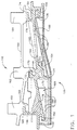
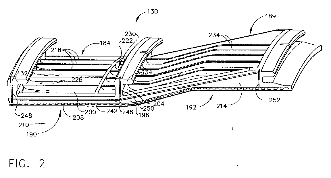
- FIG. 2 is an enlarged axial side view of an embodiment of the shroud segment of the present invention.
- FIG. 3 is an enlarged perspective view of the underside of the shroud segment of FIG. 2.
- FIGs. 4 to 6 are different enlarged portions of the shroud segment of FIG. 3.
- FIG. 7 is a top plan view of the embodiment of the shroud segment of FIG. 2.
- FIG. 8 is a sectional view taken along line 8-8 of FIG. 7.
- FIG. 9 is a top plan view of an embodiment of the shroud subassembly of the present invention with portions broken away.
- FIG. 10 is a sectional view along line 10-10 of FIG. 9.
- FIG. 11 is a similar view to FIG. 9 but showing an alternative embodiment of the shroud segment and shroud assembly of the present invention.
-
- Referring to the drawings, FIG. 1 shows an embodiment of the turbine engine cooling assembly of the present invention in the form of a shroud assembly, generally indicated as 110 for the high pressure and low pressure turbine sections of a gas turbine engine. However, with appropriate modification, the turbine engine cooling assembly of the present invention can also be suitable for providing cooling to other sections in the gas turbine engine such as the nozzle and/or vane sections.
- The shroud assembly of the present invention comprises turbine engine cooling components in the form of shroud segments indicated as 130 which can be either one-piece or two-piece. Shroud
segment 130 is provided with aforward mounting hook 132 at the circumferential leading edge thereof. Shroudsegment 130 also has a central ormid mounting hook 134 and an aft orrear mounting hook 136 at the circumferential trailing edge ofshroud segment 130. - A number of
shroud segments 130 are arranged circumferentially in a generally known fashion to form a segmented 360° shroud. A number of segmentedshroud support structures 144 are used to interconnect theshroud segments 130. Eachsegmented support 144 circumferentially spans and typically supports twoshroud segments 130, but could be appropriately modified to support one, three ormore segments 130. For the embodiment shown in FIG. 1, there are typically 26shroud segments 130 and 13 shroud supports 144 in the assembly, although other numbers of segments and supports can be suitable. - Each
segmented shroud support 144 is provided with aforward section 146, a central ormid-section 148 and an aft orrear section 150 that each respectively have forwardly projectinghangers Support structure 144 supports therespective shroud segments 130 as a result of mountinghooks hangers - Each
shroud support structure 144 is further supported by a one-piece, continuous 360° annularshroud ring structure 158. The radial position of eachshroud support 144, as well as eachshroud segment 130, is closely controlled by three distinct 360° position control rings 160, 162, and 164 provided onring structure 158. The front and mid-position control rings 160 and 162, are respectively formed with axially forwardly projectinghangers hooks sections support structure 144, while the rearposition control ring 164 is formed with an axially forwardly projectinghanger 174 that receives rearwardly projecting mountinghook 176 ofsection 150 ofsupport structure 144, to provide circumferential tongue-in-groove interconnections (hook-in-hanger). - To maximize the radial support and radial position control provided to each shroud support 144 (and thus each shroud segment 130), each
hanger support ring 158 is usually in direct axial alignment (i.e., aligned in the same radial plane) with its respectiveposition control ring support ring structure 158 is typically bolted into the combustor case (not shown) at its aft end. The entire shroud support assembly is cantilevered off its forward end at the combustor case interface. The forward and mid-position control rings, which are several inches away from the combustor aft flange, are thereby divorced from any non-uniform circumferential variations in radial deflection in the combustor case. - The segmented shroud design is typically required to accommodate the thermal growth imposed by the hostile environment created by the hot flowing exhaust gas. The segmented shroud hangers effectively cut the heat conduction path between the high temperature shroud mounting hooks and the position control rings. The position control rings are thus well isolated from the hostile and non-uniform flow path environment.
- A portion of high pressure cooling air extracted from the compressor (not shown) is fed through high pressure turbine section feed hole(s) 177 in
boss 178 ofsupport 144. This portion of cooling air then impinges upon pan-shaped high pressure turbine section impingement baffle 179 (attached to support 144), thus creating the upper high pressure (HP) turbine section's HP pre-impingement cavity orplenum 180. This portion of high pressure air is then feed through an array ofperforations 182 inbaffle 179 as cooling air into the lower HP post-impingement cavity orplenum 184 of the high pressure turbine section ofshroud segment 130. Compressor cooling air is also fed through low pressure turbine feed hole(s) 185 insupport 144. This other portion of cooling air impinges upon pan-shaped low pressure turbinesection impingement baffle 186 that is attached to support 144, thus creating the upper low pressure (LP) turbine section's LP pre-impingement cavity orplenum 187. This other portion of cooling air is then fed through perforations 188 inbaffle 186 as cooling air into the lower LP post-impingement cavity orplenum 189 of the low pressure turbine section ofshroud segment 130. - Referring to FIGs. 2, 7 and 8, each
shroud segment 130 has a forward high pressure turbine (HPT)section 190 that includes theforward mounting hook 132 at the leading edge and forward end of the shroud segment, and a rear or aft low pressure turbine (LPT)section 192 that includes aft mountinghook 136 at the trailing edge and aft end of the shroud segment. The aft end ofHPT section 190 and the forward end ofLPT section 192 ofshroud segment 130 are joined at the central ormid-mounting hook 134 and are adjacent to, respectively, the blades of the high pressure turbine and the blades of the low pressure turbine. (Forshroud segments 130 that are not one-piece,HPT section 190 andLPT section 192 can be separate pieces joined or combined together by suitable means known in the art.) - The
shroud segment 130 has a base 196 that extends from forward mounting hooking 132 to aft mountinghook 136.Base 196 has an outer or back surface, portions of which are indicated as 200 in the HPT section and 204 in the LPT section.Base 196 also has aninner surface 208 that is contact with the main (hot) gas stream indicated byarrow 210 that generally moves downstream in the direction from the leading to the trailing end of theshroud segment 130. As shown in FIG. 2,inner surface 208 extends generally straight from the forward end to the aft end of theHPT section 190, but then extends diagonally upward at the forward end of theLPT section 192 to about the midpoint thereof and then extends generally straight thereafter to the aft end of the LPT section. The shroud segment also has a pair of opposed spaced side rails orpanels 214 that are connected at their leading and trailing ends by mountinghooks hook 134 and at their bottom edges bybase 196. - As also shown in FIGs. 2, 7 and 8,
HPT section 190 has a plurality of spacedlongitudinal ribs 218 that are connected at their respective ends by mountinghooks base 196. A laterally extendingrib 222 is connected at its respective ends byside panels 214, and at the bottom edge bybase 196 and divides the HP post-impingement cavity 184 (framed by mountinghooks side panels 214 and base 196) into a forward higher pressure HP post-impingement pocket indicated as 226 and an aft lower pressure HP post sub-impingement pocket indicated as 230. The aft HPsub-impingement pocket 230 is fed cooling air through perforations in a secondary impingement baffle (not shown) located on top of thecircumferential ribs 222 and extending aft to themid-mounting hook 134 with its edges extending between the tworespective side panels 214, this secondary impingement baffle also being fed cooling air from the HPpost-impingement cavity 184.LPT section 192 also has a plurality of spacedlongitudinal ribs 234 that are connected at their respective ends by mountinghooks base 196, as well as LP post-impingement cavity 189 (framed by mountinghooks side panels 214 and base 196) that receives the cooling air fed through the perforations 188 inbaffle 186. - As shown in FIGs. 2 and 3, each of the
side panels 214 have a lower or discourager seal groove orslot 242 and an upper or primary seal groove or slot 246 spaced abovelower slot 242.Slots shroud segment 130 and terminate at about the trailing edge or aft end forlower slot 242 and at the aft end of the lower pressure impingement cavity forupper slot 246. Whileslots - Also shown in FIGs. 2 and 3 are a forward vertical seal groove or slot 248 at mounting
hook 132, a central or mid-position vertical seal groove or slot 250 at mountinghook 134, and an aft vertical seal groove or slot 252 at mountinghook 136. Each of thevertical slots inner surface 208 ofbase 196 and extend upwardly to perpendicularly intersect lower andupper slots - Referring to FIGs. 4 and 10,
lower slot 242 has abottom wall 256, aside wall 260 connected at an edge tobottom wall 256 and atop wall 264 connected at an edge toside wall 260, whileupper slot 246 has abottom wall 266, aside wall 270 connected at an edge tobottom wall 266 and atop wall 274 connected at an edge toside wall 270. As shown particularly in FIG. 4,bottom wall 256 oflower slot 242 has a plurality of spaced alternatinglands 278 and slots or recesses 282. While thelands 278 and recesses 282 are shown as having similar sizes and a square configuration, different sizes, as well as other shapes and configurations (such as rounded edges) can also be suitable. - As shown particularly FIGs. 4, 9 and 10, a plurality of elongated air cooling holes or
passages 286 withinlets 288 at outer or back surfaces 200 or 204 ofbase 196 extend diagonally downward and radially inward throughbase 196 ofshroud segment 130 and are shown in FIGs. 4, 9 and 10 as exiting throughoutlets 292 through thetop wall 264 oflower slot 242, or as shown alternatively,outlets 292 can exit at about the edge connectingside wall 260 andtop wall 264. For the embodiments of the present invention shown in FIG. 4, it is also important that eachoutlet 292 exit above one of thelands 278 for reasons to be described hereafter. However, if desired for other embodiments of the present invention,outlets 292 ofpassages 286 can also exit at other points onside panel 214 between thebottom wall 266 ofupper slot 246 and thebottom wall 256 oflower slot 242. -
Passages 286 are usually straight and can be skewed relative to the circumferential direction and the radial direction. This skewing affords thepassages 286 greater lengths, significantly greater than the base and side rail or panel thicknesses, and increases their convection cooling surfaces. Thepassages 286 are typically spaced along theHPT section 190 and theLPT section 192 such that theirrespective outlets 292 that exit intolower slot 242 are also spaced along the entire length of the lower slot. Whilepassages 286 exit throughoutlets 292 in a continuous pattern along the entire length ofslot 242, it is preferred in the shroud segments of the present invention that such passages not exit at certain sections of the lower slot to economize the usage of the total cooling air flow. One such section, shown in FIG. 5, is at about the transition point indicated as 296 between the aft end ofHPT section 190 and the forward end of theLPT section 192. By leaving outpassages 286 at thistransition point 296, the wasteful flow of cooling air from the HPT section to the LPT section is prevented or minimized. As shown in FIG. 6, another such section where coolingair passages 286 are typically unnecessary is at the point indicated as 300 at about the trailing edge or aft end of the LPT section. At this point in the LPT section, there is usually sufficient air flow axially and aft alonglower slot 242 to adequatelycool side panels 214 without additional cooling air being delivered bypassages 286, again avoiding the wasteful use of the total cooling air flow. - The forward HP
post-impingement pocket 226 feeds cooling air toinlets 288 ofpassages 286 that exit throughoutlets 292 in the forward portion of theHPT section 190, while aftsub-impingement pocket 230 feeds cooling air toinlets 288 ofpassages 286 that exit throughoutlets 292 in the aft portion of theHPT section 190. Thesub-impingement pocket 230 is important for conserving the total cooling air flow with respect to the last few (typically 4)passages 286 that exit throughoutlets 292 at the aft end ofHPT section 190. In particular,pocket 230 reduces the pressure of the cooling air flow frompost-impingement plenum 184 before it entersinlets 288 ofpassages 286 at the aft end ofHPT section 190. - As shown in FIGs. 3 to 6,
shroud segment 130 can have additional rows of cooling passages, five of which are indicated as 304, 306, 308, 310 and 312 that extend from the outer or back surfaces 200 or 204 ofbase 196, throughbase 196 and then exit throughoutlets 314 frominner surface 208. Likepassages 286,passages rows cool HPT section 190 andLPT section 192 ofshroud segment 130. Having served this purpose, the cooling air exiting fromoutlets 314 of these rows of passages mixes flows alonginner surface 208 to film cool the shroud segment. - Another aspect of the present invention is the shroud subassembly, an embodiment of which is shown in FIGs. 9 and 10 and is indicated generally as 400. As shown particularly in FIG. 10,
subassembly 400 comprises a pair ofadjacent shroud segments 130 that have opposedadjacent side panels 214 that are separated by an circumferential segment gap generally indicated as 402. As particularly shown in FIG. 9, thelands 278 and recesses 282 oflower slot 242 of each of theadjacent side panels 214 are spaced to be staggered or offset relative to each other such that the lands of the lower slot of each adjacent side panel are opposite the recesses of each adjacent side panel. As a result, each of thecooling passages 286 havingoutlets 292 exiting into the lower slot 242 (above one of the lands 278) are also opposite arecess 282 of the lower slot of the adjacent side panel. - As shown in FIGs. 2, 3, and 9, the alternating
lands 278 and recesses 282 typically extend continuously along thebottom wall 256 of the entire length oflower slot 242 of each of theadjacent side panels 214. However, these alternatinglands 278, and especially recesses 282, need not be continuous or along the entire length oflower slot 242. For example, for those sections of the lower slot 242 (such as those shown in FIGs. 5 and 6) wherepassages 286 do not exit intolower slot 242, that portion ofbottom wall 256 of thelower slot 242 of theadjacent side panel 214 need not haverecesses 282 formed therein. - Subassembly 400 further comprises a lower
discourager spline seal 404 positioned ingap 402 that has spacededges 408 that are received by lower slots 242 (above the lands 278) of theadjacent side panels 214 of the pair ofshroud segments 130. Subassembly 400 also includes an upperprimary spline seal 412 positioned ingap 402 that has spacededges 416 that are received byupper slots 246 of theadjacent side panels 214 of the pair ofshroud segments 130. Thediscourager seal 404 andprimary seal 412 essentially dividegap 402 into three sections that are referred to hereafter as the bottom cavity ortrench 420, the intermediate pressure cavity orchute 424 and the toppost-impingement cavity 428. The intermediate pressure cavity orchute 424 defined between thediscourager seal 404 and theprimary seal 412 is typically divided into a forward HPT portion and an aft LPT portion by the vertical spline seal received by the respective central ormid-vertical slots 250 of each of theadjacent side panels 214. Thischute 424 has a pressure lower than the pressure of the HPpost-impingement cavity 184 and the LPpost-impingement cavity 189 and higher than localgas stream pressure 210, i.e., in the vicinity ofHPT section 190 andLPT section 192. - The width of each of
seals 412 and especially 404 is such that they are smaller than the combined width ofgap 402 andslots adjacent side panels 214. This is particularly important forlower slots 242 of eachadjacent side panel 214 so that the portion of eachrecess 282adjacent side wall 260 can remain uncovered byseal 404 and thus be accessible to air flow. Whileseals slots - As shown particularly in FIG. 10, cooling air indicated by
arrow 432 flows downpassage 286 and exitsoutlet 292. At this point, thisair flow 432 can go via one of two pathways which can provide impingement cooling to those portions ofside panels 214adjacent trench 420. One pathway is to flow axially downstream inchute 424 towards the trailing edge ofshroud segment 130 and exit from arecess 282 on the same side aspassage 286 from whichair flow 432 came, intotrench 420 to impinge on the portion belowseal 404, as indicated by 448, of theadjacent side panel 214 and to purge the hot gas intrench 420. The other pathway is to flow circumferentially overdiscourager seal 404 to enterlower slot 242 of theadjacent panel 214 as indicated byarrow 440, flow aroundedge 408 ofseal 404 and into the uncovered portion ofrecess 282adjacent side wall 260 as indicated byarrow 444, and then out ofrecess 282 as indicated byarrow 446 intotrench 420 to impinge on the portion belowseal 404, as indicated by 448, of thesame side panel 214 from which theair flow 432 came and to purge the hot gas intrench 420. (As shown in FIG. 10, thelower portion 448 of each of therespective side panels 214 also includes the thermal barrier coating indicated by 454 that is attached to the metal portion ofshroud segment 130 by a bond coat indicated by 456.) - Because
discourager seal 404 is typically not stationary but can move freely withlower slots 242, it is possible foredges 408 to butt againstside wall 260 ofslot 242 and thus coverrecesses 282 so they are partially or completely inaccessible to the flow air. As shown in FIG. 11, an alternative embodiment of the present invention is to extend eachrecess 282 into and upside wall 260 above theadjacent lands 278 ofslot 242 as indicated by 460 so that ifedges 408 ofseal 404 do butt againstside wall 260 ofslot 242, recesses 282 will remain uncovered byseal 404 and thus accessible to the flow of air. While the embodiment of the present invention shown in FIGs. 9 to 11 provides air flow pathways spaced along the length oflower slot 242 in the form ofrecesses 282 for receiving air flowing into slot 242 (see arrow 440) that then flows over and around theedge 408 of the seal 404 (see arrow 444) and then passing that air flow beneath seal 404 (see arrow 446), other designs of air flow pathways that are belowbottom wall 266 of upper slot 246 (and primary seal 412) are also suitable. For example, a plurality of spaced arcuate passages could be formed inside panels 214 that are opposite therespective outlets 292 ofpassages 286 and have inlets above and outlets belowlower slot 242 so that the flow ofair 432 inchute 424 can be directed around and beneathseal 404. - For the sake of good order, various aspects of the invention are set out in the following clauses:-
- 1. A turbine engine cooling component for a gas turbine engine, which
comprises:
- (a) a circumferential leading edge;
- (b) a circumferential trailing edge spaced from the leading edge;
- (c) an arcuate base connected to the trailing and leading edges and having a back surface and an arcuate inner surface that is in contact with the main gas stream of the gas turbine engine moving in the direction from the leading edge to the trailing edge of the turbine component;
- (d) a pair of spaced opposed axial side panels connected to the leading and trailing edges;
- (e) each of the side panels having a lower discourager spline seal slot extending longitudinally from the leading edge to the trailing edge of each side panel that is capable of receiving an edge of a discourager spline seal, each lower slot having at least a bottom wall and a top wall;
- (f) each of the side panels having an upper primary spline seal slot spaced above the lower slot and extending longitudinally from the leading edge to the trailing edge of each side panel that is capable of receiving an edge of a primary spline seal, each upper slot having at least a bottom wall and a top wall,
- (g) a plurality of cooling air passages extending through the base from the back surface thereof and having spaced outlets exiting from at least one of the side panels between the bottom wall of the top slot and the bottom wall of the lower slot;
- (h) a plurality of spaced air flow pathways along the length of the lower slot and below the bottom wall of the upper slot that are capable of receiving air flowing over and above the discourager seal when positioned in the lower slot and passing that air flow around the edge and beneath the discourager seal.
- 2. The turbine component of
clause 1 wherein the plurality of air flow pathways are a plurality of spaced recesses along the bottom wall of the lower slot. - 3. The turbine component of
clause 2 wherein the bottom wall of the lower slot has a plurality of spaced alternating recesses and lands and wherein each of the outlets of the passages exiting the side panels exit into the lower slot above one of the lands. - 4. The turbine component of clause 3 wherein the lower slot has a side wall connecting the bottom wall and the top wall at an edge thereof and wherein the outlets of the passages exit at about the edge connecting the side wall and the top wall.
- 5. The turbine component of clause 4 wherein each recess extends into the side wall and above the adjacent lands.
- 6. The turbine component of
clause 2 wherein the upper and lower slots extend continuously from the leading edge to the trailing edge of each side panel. - 7. The turbine component of
clause 1 which is a shroud cooling segment for a high pressure turbine section, a low pressure turbine section or both. - 8. A turbine engine cooling subassembly, which comprises:
- (1) an adjacent pair of the turbine components of
clause 1 having opposed adjacent side panels with a gap therebetween and wherein the spacing of the air flow pathways along the length of the lower slot for each of the adjacent side panels is staggered such that the outlet of each of the passages exiting each adjacent side panel are opposite one of the air flow pathways of the other adjacent side panel; - (2) at least one discourager spline seal positioned in the gap and including a pair of spaced edges having a length and thickness such that each of the edges is capable of being received by the lower slot of one of the adjacent side panels;
- (3) the at least one discourager seal being positioned below the outlet of each of the passages exiting each adjacent side panel;
- (4) at least one primary spline seal positioned in the gap and including a pair of spaced edges having a length and thickness such that each of the edges is capable of being received by the upper slot of one of the adjacent side panels.
- 9. The turbine subassembly of
clause 8 wherein each of the discourager and primary seals are one continuous piece. - 10. A cooling shroud segment for the high pressure and low pressure
turbine sections of a gas turbine engine, which has a forward high pressure
turbine section and an aft low pressure turbine section and which comprises:
- (a) a circumferential leading edge at the forward end of the high pressure turbine section;
- (b) a circumferential trailing edge spaced from the leading edge at the aft end of the low pressure turbine section;
- (c) an arcuate base connected to the trailing and leading edges and having a back surface and an arcuate inner surface that is in contact with the main gas stream of the gas turbine engine moving in the direction from the leading edge to the trailing edge of the shroud segment;
- (d) a pair of spaced opposed axial side panels connected to the leading and trailing edges;
- (e) each of the side panels having a lower discourager spline seal slot extending longitudinally from the leading edge to the trailing edge of each side panel, each lower slot having a bottom wall, a top wall, and a side wall connected to the bottom and top walls at an edge thereof, the bottom wall having a plurality of spaced alternating lands and recesses along the length thereof;
- (f) each of the side panels having an upper primary spline seal slot spaced above the lower slot and extending longitudinally from the leading edge to the trailing edge of each side panel, each upper slot having at least a bottom wall and a top wall,
- (g) a plurality of cooling air passages extending through the base from the back surface thereof and having outlets exiting into the lower slot of at least one of the side panels and above one of the lands of the bottom wall of the lower slot.
- 11. The shroud segment of
clause 10 wherein the upper and lower slots extend continuously from the leading edge to the trailing edge of each side panel. - 12. The shroud segment of
clause 11 wherein no passages exit into the lower slot at about the transition from the aft end of the high pressure turbine section to the forward end of the low pressure turbine section of the shroud segment. - 13. The shroud segment of clause 12 wherein no passages exit into the lower slot at about the trailing edge of the low pressure turbine section of the shroud segment.
- 14. The shroud segment of
clause 11 wherein the outlets of the passages exit at about the edge connecting the side wall and the top wall. - 15. The shroud segment of
clause 11 wherein each recess extends into the side wall and above the adjacent lands. - 16. The shroud segment of
clause 11 wherein the high pressure turbine section has a forward post-impingement pocket that feeds cooling air into the passages having outlets exiting into the lower slot at the forward end of the high pressure turbine section and an aft sub-impingement pocket that feeds cooling air into the passages having outlets exiting into the lower slot at the aft end of the high pressure turbine section. - 17. A shroud subassembly for the high pressure and low pressure turbine
sections of a gas turbine engine, which comprises:
- (a) a pair of adjacent shroud segments, each of the shroud segments
comprising a high pressure turbine section having a high pressure
impingement cavity and a low pressure turbine section having a low pressure
impingement cavity, each shroud segment further comprising:
- (1) a circumferential leading edge at the forward end of the high pressure turbine section;
- (2) a circumferential trailing edge spaced from the leading edge at the aft end of the low pressure turbine section;
- (3) an arcuate base connected to the trailing and leading edges and having a back surface and an arcuate inner surface that is in contact with the main gas stream of the gas turbine engine moving in the direction from the leading edge to the trailing edge of the shroud segment;
- (4) a pair of spaced opposed axial side panels connected to the leading and trailing edges;
- (5) each of the side panels having a lower discourager spline seal slot extending longitudinally from the leading edge to the trailing edge of each side panel, each lower slot having a bottom wall, a top wall, and a side wall connected to the bottom and top wall at an edge thereof, the bottom wall having a plurality of spaced alternating lands and recesses along the length thereof;
- (6) each of the side panels having an upper primary spline seal slot above the lower slot and extending longitudinally from the leading edge to the trailing edge of each side panel, each upper slot having at least a bottom wall and a top wall;
- (7) a plurality of cooling air passages extending through the base from the back surface thereof and having outlets exiting into the lower slot of at least one of the side panels and above one of the lands of the bottom wall of the lower slot;
- (8) wherein the opposed adjacent side panels of the pair of shroud segments have a gap therebetween and wherein the spacing of the lands and recesses in the bottom wall of the lower slot for each of the adjacent side panels is staggered such that the lands of one of the adjacent panels are opposite the recesses of the other adjacent side panel;
- (b) at least one discourager spline seal positioned in the gap and including a pair of spaced edges having a length and thickness such that each of the edges is capable of being received by the lower slot of one of the adjacent side panels;
- (c) the at least one discourager seal being positioned above each land of the bottom wall of each lower slot and below the outlets exiting into each lower slot and having a width smaller than the combined width of the gap and the bottom wall of the lower slots of the adjacent side panels such that at least a portion of each recess of the bottom wall adjacent the side wall of each lower slot is capable of being accessible to air flow;
- (d) at least one primary spline seal positioned in the gap and including a pair of spaced edges having a length and thickness such that each of the edges is capable of being received by the upper slot of one of the adjacent side panels;
- (e) the at least one discourager seal and the at least one primary seal defining therebetween an intermediate pressure cavity having a pressure lower than the pressure of the high pressure impingement cavity and the low pressure impingement cavity and a pressure higher than the pressure of the main gas stream in the vicinity of high pressure turbine and low pressure turbine sections of the shroud segment.
- 18. The shroud subassembly of clause 17 wherein the upper and lower slots extend continuously from the leading edge to the trailing edge of each side panel.
- 19. The shroud subassembly of clause 18 wherein each of the discourager and primary seals are one continuous piece.
- 20. The shroud subassembly of clause 18 wherein, for each shroud segment, no cooling air passages exit into the lower slot at about the transition from the aft end of the high pressure turbine section to the forward end of the low pressure turbine section and at about the trailing edge of the low pressure turbine section.
-
Claims (10)
- A turbine engine cooling component (130) for a gas turbine engine, which comprises:(a) a circumferential leading edge (132);(b) a circumferential trailing edge (136) spaced from the leading edge (132;(c) an arcuate base (196) connected to the trailing and leading edges (132, 136) and having a back surface (200, 204) and an arcuate inner surface (208) that is in contact with the main gas stream (210) of the gas turbine engine moving in the direction from the leading edge (132) to the trailing edge (136) of the turbine component (130);(d) a pair of spaced opposed axial side panels (214) connected to the leading and trailing edges (132, 136);(e) each of the side panels (214) having a lower discourager spline seal slot (242) extending longitudinally from the leading edge (132) to the trailing edge (136) of each side panel (214) that is capable of receiving an edge (408) of a discourager spline seal (404), each lower slot (242) having at least a bottom wall (256) and a top wall (264);(f) each of the side panels (214) having an upper primary spline seal slot (246) spaced above the lower slot (242) and extending longitudinally from the leading edge (132) to the trailing edge (136) of each side panel (214) that is capable of receiving an edge (416) of a primary spline seal (412), each upper slot (246) having at least a bottom wall (266) and a top wall (274),(g) a plurality of cooling air passages (286) extending through the base (196) from the back surface thereof (200, 204) and having spaced outlets (292) exiting from at least one of the side panels (214) between the bottom wall (266) of the top slot (246) and the bottom wall (256) of the lower slot (242);(h) a plurality of spaced air flow pathways (282) along the length of the lower slot (242) and below the bottom wall (266) of the upper slot (246) that are capable of receiving air flowing over and above the discourager seal (404) when positioned in the lower slot (242) and passing that air flow around the edge (408) and beneath the discourager seal (404).
- The turbine component (130) of claim 1 wherein the plurality of air flow pathways (282) are a plurality of spaced recesses (282) along the bottom wall (256) of the lower slot (242).
- The turbine component (130) of claim 2 wherein the bottom wall (256) of the lower slot (242) has a plurality of spaced alternating recesses (282) and lands (278) and wherein each of the outlets (292) of the passages (286) exiting the side panels (214) exit into the lower slot (242) above one of the lands (278).
- A turbine engine cooling subassembly (400), which comprises:(1) an adjacent pair of the turbine components (130) of claim 1 having opposed adjacent side panels (214) with a gap (402) therebetween and wherein the spacing of the air flow pathways (282) along the length of the lower slot (242) for each of the adjacent side panels (214) is staggered such that the outlet (292) of each of the passages (286) exiting each adjacent side panel (214) are opposite one of the air flow pathways (282) of the other adjacent side panel (214);(2) at least one discourager spline seal (404) positioned in the gap (402) between the opposed adjacent side panels (214) and including a pair of spaced edges (408) having a length and thickness such that each of the edges (408) is capable of being received by the lower slot (242) of one of the adjacent side panels (214);(3) the at least one discourager seal (404) being positioned below the outlet (292) of each of the passages (286) exiting each adjacent side panel (214);(4) at least one primary spline seal (412) positioned in the gap (402) and including a pair of spaced edges (416) having a length and thickness such that each of the edges (416) is capable of being received by the upper slot (246) of one of the adjacent side panels (214).
- The turbine subassembly (400) of claim 4 wherein each of the discourager and primary seals (404, 412) are one continuous piece.
- A cooling shroud segment (130) for the high pressure and low pressure turbine sections of a gas turbine engine, which has a forward high pressure turbine section (190) and an aft low pressure turbine section (192) and which comprises:(a) a circumferential leading edge (132) at the forward end of the high pressure turbine section (190);(b) a circumferential trailing edge (136) spaced from the leading edge (132) at the aft end of the low pressure turbine section (192);(c) an arcuate base (196) connected to the trailing and leading edges (132, 136) and having a back surface (200, 204) and an arcuate inner surface (208) that is in contact with the main gas stream (210) of the gas turbine engine moving in the direction from the leading edge (132) to the trailing edge (136) of the shroud segment (130);(d) a pair of spaced opposed axial side panels (214) connected to the leading and trailing edges (132, 136);(e) each of the side panels (214) having a lower discourager spline seal slot (242) extending longitudinally from the leading edge (132) to the trailing edge (136) of each side panel (214), each lower slot (242) having a bottom wall (256), a top wall (264), and a side wall (256) connected to the bottom and top walls (256, 264) at an edge thereof, the bottom wall (256) having a plurality of spaced alternating lands (278) and recesses (282) along the length thereof;(f) each of the side panels (214) having an upper primary spline seal slot (246) spaced above the lower slot (242) and extending longitudinally from the leading edge (132) to the trailing edge (136) of each side panel (214), each upper slot (246) having at least a bottom wall (266) and a top wall (274);(g) a plurality of cooling air passages (286) extending through the base (196) from the back surface thereof (200, 204) and having outlets (292) exiting into the lower slot (242) of at least one of the side panels (214) and above one of the lands (278) of the bottom wall (256) of the lower slot (242).
- The shroud segment (130) of claim 6 wherein the upper and lower slots (246, 242) extend continuously from the leading edge (132) to the trailing edge (136) of each side panel (214).
- The shroud segment (130) of claim 7 wherein no passages (286) exit into the lower slot (242) at about the transition (296) from the aft end of the high pressure turbine section (190) to the forward end of the low pressure turbine section (192) of the shroud segment (130).
- A shroud subassembly (400) for the high pressure and low pressure turbine sections of a gas turbine engine, which comprises:(a) a pair of adjacent shroud segments (130), each of the shroud segments (130) comprising a high pressure turbine section (190) having a high pressure impingement cavity (184) and a low pressure turbine section having a low pressure impingement cavity (189), each shroud segment (130) further comprising:(1) a circumferential leading edge (132) at the forward end of the high pressure turbine section (190);(2) a circumferential trailing edge (136) spaced from the leading edge (132) at the aft end of the low pressure turbine section (192);(3) an arcuate base (196) connected to the trailing and leading edges (132, 136) and having a back surface (200, 204) and an arcuate inner surface (208) that is in contact with the main gas stream (210) of the gas turbine engine moving in the direction from the leading edge (132) to the trailing edge (136) of the shroud segment (130);(4) a pair of spaced opposed axial side panels (214) connected to the leading and trailing edges (132, 136);(5) each of the side panels (214) having a lower discourager spline seal slot (242) extending longitudinally from the leading edge (132) to the trailing edge (136) of each side panel (214), each lower slot (242) having a bottom wall (256), a top wall (264), and a side wall (256) connected to the bottom and top walls (256, 264) at an edge thereof, the bottom wall (256) having a plurality of spaced alternating lands (278) and recesses (282) along the length thereof;(6) each of the side panels (214) having an upper primary spline seal slot (246) spaced above the lower slot (242) and extending longitudinally from the leading edge (132) to the trailing edge (136) of each side panel (214), each upper slot (246) having at least a bottom wall (266) and a top wall (274);(7) a plurality of cooling air passages (286) extending through the base (196) from the back surface thereof (200, 204) and having outlets (292) exiting into the lower slot (242) of at least one of the side panels (214) and above one of the lands (278) of the bottom wall (256) of the lower slot (242);(8) wherein the opposed adjacent side panels (214) of the pair of shroud segments (130) have a gap (402) therebetween and wherein the spacing of the lands (278) and recesses (282) in the bottom wall (256) of the lower slot (242) for each of the adjacent side panels (214) is staggered such that the lands (278) of one of the adjacent panels (214) are opposite the recesses (282) of the other adjacent side panel (282);(b) at least one discourager spline seal (404) positioned in the gap (402) between the opposed adjacent side panels (214) and including a pair of spaced edges (408) having a length and thickness such that each of the edges (408) is capable of being received by the lower slot (242) of one of the adjacent side panels (214);(c) the at least one dis courager seal (404) being positioned above each land (278) of the bottom wall (256) of each lower slot (242) and below the outlets (292) exiting into each lower slot (242) and having a width smaller than the combined width of the gap (402) and the bottom wall (256) of the lower slots (242) of the adjacent side panels (214) such that at least a portion of each recess (282) of the bottom wall (256) adjacent the side wall (260) of each lower slot (242) is capable of being accessible to air flow;(d) at least one primary spline seal (412) positioned in the gap (402) and including a pair of spaced edges (416) having a length and thickness such that each of the edges (416) is capable of being received by the upper slot (246) of one of the adjacent side panels (214);(e) the at least one discourager seal (404) and the at least one primary seal (412) defining therebetween an intermediate pressure cavity (424) having a pressure lower than the pressure of the high pressure impingement cavity (184) and the low pressure impingement cavity (189) and a pressure higher than the pressure of the main gas stream (21) in the vicinity of high pressure turbine and low pressure turbine sections (190, 192) of the shroud segment (130).
- The shroud subassembly (400) of claim 9 wherein the upper and lower slots (242, 246) extend continuously from the leading edge (132) to the trailing edge (136) of each side panel (214).
Applications Claiming Priority (2)
| Application Number | Priority Date | Filing Date | Title |
|---|---|---|---|
| US590590 | 2000-06-08 | ||
| US09/590,590 US6340285B1 (en) | 2000-06-08 | 2000-06-08 | End rail cooling for combined high and low pressure turbine shroud |
Publications (3)
| Publication Number | Publication Date |
|---|---|
| EP1162346A2 true EP1162346A2 (en) | 2001-12-12 |
| EP1162346A3 EP1162346A3 (en) | 2004-01-14 |
| EP1162346B1 EP1162346B1 (en) | 2010-03-10 |
Family
ID=24362842
Family Applications (1)
| Application Number | Title | Priority Date | Filing Date |
|---|---|---|---|
| EP01303095A Expired - Lifetime EP1162346B1 (en) | 2000-06-08 | 2001-03-30 | Cooled turbine component, shroud segment, and corresponding assemblies |
Country Status (5)
| Country | Link |
|---|---|
| US (1) | US6340285B1 (en) |
| EP (1) | EP1162346B1 (en) |
| JP (1) | JP4553285B2 (en) |
| DE (1) | DE60141497D1 (en) |
| ES (1) | ES2340913T3 (en) |
Cited By (27)
| Publication number | Priority date | Publication date | Assignee | Title |
|---|---|---|---|---|
| EP1225308A2 (en) * | 2001-01-15 | 2002-07-24 | Mitsubishi Heavy Industries, Ltd. | Split ring for gas turbine casing |
| WO2003054360A1 (en) * | 2001-12-13 | 2003-07-03 | Alstom Technology Ltd | Hot gas path subassembly of a gas turbine |
| WO2003054359A1 (en) * | 2001-12-13 | 2003-07-03 | Alstom Technology Ltd | Sealing module for components of a turbo-engine |
| EP1586743A1 (en) * | 2004-04-15 | 2005-10-19 | Snecma | Turbine shroud |
| WO2006029889A1 (en) * | 2004-09-17 | 2006-03-23 | Nuovo Pignone S.P.A. | Protection device for a turbine stator |
| FR2919345A1 (en) * | 2007-07-26 | 2009-01-30 | Snecma Sa | Cylindrical or truncated ring for e.g. jet prop engine, has internal slots housing internal blades between discharge ends of channels and internal longitudinal edges of radial surfaces, where blades extend on axial length of ring sectors |
| CN101922353A (en) * | 2009-03-31 | 2010-12-22 | 通用电气公司 | From the seal groove feeding film cooling hole |
| EP2365188A1 (en) * | 2010-03-03 | 2011-09-14 | General Electric Company | Cooling gas turbine components with seal slot channels |
| EP2369135A3 (en) * | 2010-03-26 | 2012-05-16 | United Technologies Corporation | Blade outer air seal for a gas turbine engine and corresponding gas turbine engine |
| EP1541809A3 (en) * | 2003-12-12 | 2012-10-17 | Rolls-Royce Plc | Cooled platform for a nozzle guide vane |
| FR2974839A1 (en) * | 2011-05-04 | 2012-11-09 | Snecma | Sectorized ring for use in rotor of high pressure gas turbine of turbojet of aircraft, has ventilation openings whose cross section at slits is greater than width of slits so as to have lower and upper cooling zones on sides of strips |
| EP1930549A3 (en) * | 2006-11-30 | 2013-01-16 | General Electric Company | Methods and systems for cooling integral turbine shroud assemblies |
| US8371807B2 (en) | 2004-09-17 | 2013-02-12 | Nuovo Pignone, S.P.A. | Protection device for a turbine stator |
| CN103195499A (en) * | 2012-01-05 | 2013-07-10 | 通用电气公司 | Device and method for sealing a gas path in a turbine |
| WO2014014762A1 (en) | 2012-07-16 | 2014-01-23 | United Technologies Corporation | Blade outer air seal with cooling features |
| WO2014193618A1 (en) * | 2013-05-28 | 2014-12-04 | Siemens Energy, Inc. | Cooling system for three hook ring segment |
| EP2851517A1 (en) * | 2013-05-14 | 2015-03-25 | Rolls-Royce plc | A shroud arrangement for a gas turbine engine |
| EP2987959A3 (en) * | 2014-08-22 | 2016-03-16 | Rolls-Royce Corporation | Seal with cooling feature |
| EP2890878A4 (en) * | 2012-08-29 | 2016-07-20 | United Technologies Corp | Blade outer air seal |
| CZ306302B6 (en) * | 2003-01-22 | 2016-11-23 | General Electric Company | Stator shroud and stator shroud segment of multistage gas turbine |
| CN106194277A (en) * | 2015-05-29 | 2016-12-07 | 通用电气公司 | The spline seal of impinging cooling |
| EP3130760A1 (en) * | 2015-08-14 | 2017-02-15 | United Technologies Corporation | Blade outer air seal for a gas turbine engine |
| EP2631434A3 (en) * | 2012-02-22 | 2017-07-26 | General Electric Company | Low-ductility turbine shroud |
| EP2615254A3 (en) * | 2012-01-10 | 2017-08-02 | General Electric Company | Gas turbine stator assembly having abuting components with slots for receiving a sealing member |
| EP3184212A3 (en) * | 2015-12-21 | 2017-11-29 | Pratt & Whitney Canada Corp. | Method of sizing a cavity in a part |
| WO2018156293A1 (en) * | 2017-02-24 | 2018-08-30 | General Electric Company | Spline for a turbine engine |
| EP3667024A1 (en) * | 2018-12-12 | 2020-06-17 | Rolls-Royce plc | Seal segment for a shroud ring of a gas turbine engine |
Families Citing this family (92)
| Publication number | Priority date | Publication date | Assignee | Title |
|---|---|---|---|---|
| GB2378730B (en) * | 2001-08-18 | 2005-03-16 | Rolls Royce Plc | Cooled segments surrounding turbine blades |
| US6843479B2 (en) * | 2002-07-30 | 2005-01-18 | General Electric Company | Sealing of nozzle slashfaces in a steam turbine |
| US7033138B2 (en) * | 2002-09-06 | 2006-04-25 | Mitsubishi Heavy Industries, Ltd. | Ring segment of gas turbine |
| DE10303340A1 (en) * | 2003-01-29 | 2004-08-26 | Alstom Technology Ltd | cooling device |
| US6971844B2 (en) * | 2003-05-29 | 2005-12-06 | General Electric Company | Horizontal joint sealing system for steam turbine diaphragm assemblies |
| US7524163B2 (en) * | 2003-12-12 | 2009-04-28 | Rolls-Royce Plc | Nozzle guide vanes |
| DE102004016222A1 (en) * | 2004-03-26 | 2005-10-06 | Rolls-Royce Deutschland Ltd & Co Kg | Arrangement for automatic running gap adjustment in a two-stage or multi-stage turbine |
| US7284954B2 (en) * | 2005-02-17 | 2007-10-23 | Parker David G | Shroud block with enhanced cooling |
| US20070160475A1 (en) * | 2006-01-12 | 2007-07-12 | Siemens Power Generation, Inc. | Tilted turbine vane with impingement cooling |
| US7665960B2 (en) * | 2006-08-10 | 2010-02-23 | United Technologies Corporation | Turbine shroud thermal distortion control |
| US7771160B2 (en) * | 2006-08-10 | 2010-08-10 | United Technologies Corporation | Ceramic shroud assembly |
| US7527472B2 (en) * | 2006-08-24 | 2009-05-05 | Siemens Energy, Inc. | Thermally sprayed conformal seal |
| FR2906846B1 (en) * | 2006-10-06 | 2008-12-26 | Snecma Sa | CHANNEL TRANSITION BETWEEN TWO TURBINE STAGES |
| FR2907841B1 (en) * | 2006-10-30 | 2011-04-15 | Snecma | TURBINE MACHINE RING SECTOR |
| US7722315B2 (en) * | 2006-11-30 | 2010-05-25 | General Electric Company | Method and system to facilitate preferentially distributed recuperated film cooling of turbine shroud assembly |
| US7740442B2 (en) * | 2006-11-30 | 2010-06-22 | General Electric Company | Methods and system for cooling integral turbine nozzle and shroud assemblies |
| US7665953B2 (en) * | 2006-11-30 | 2010-02-23 | General Electric Company | Methods and system for recuperated cooling of integral turbine nozzle and shroud assemblies |
| US7785067B2 (en) * | 2006-11-30 | 2010-08-31 | General Electric Company | Method and system to facilitate cooling turbine engines |
| US7690885B2 (en) * | 2006-11-30 | 2010-04-06 | General Electric Company | Methods and system for shielding cooling air to facilitate cooling integral turbine nozzle and shroud assemblies |
| US7611324B2 (en) * | 2006-11-30 | 2009-11-03 | General Electric Company | Method and system to facilitate enhanced local cooling of turbine engines |
| US7604453B2 (en) * | 2006-11-30 | 2009-10-20 | General Electric Company | Methods and system for recuperated circumferential cooling of integral turbine nozzle and shroud assemblies |
| US7922444B2 (en) * | 2007-01-19 | 2011-04-12 | United Technologies Corporation | Chamfer rail pockets for turbine vane shrouds |
| JP4690353B2 (en) * | 2007-03-09 | 2011-06-01 | 株式会社日立製作所 | Gas turbine sealing device |
| MX2009011266A (en) * | 2007-04-19 | 2009-11-02 | Alstom Technology Ltd | Stator heat shield. |
| US8469656B1 (en) | 2008-01-15 | 2013-06-25 | Siemens Energy, Inc. | Airfoil seal system for gas turbine engine |
| US8147192B2 (en) * | 2008-09-19 | 2012-04-03 | General Electric Company | Dual stage turbine shroud |
| GB0910177D0 (en) * | 2009-06-15 | 2009-07-29 | Rolls Royce Plc | A cooled component for a gas turbine engine |
| US8167546B2 (en) * | 2009-09-01 | 2012-05-01 | United Technologies Corporation | Ceramic turbine shroud support |
| US8079807B2 (en) * | 2010-01-29 | 2011-12-20 | General Electric Company | Mounting apparatus for low-ductility turbine shroud |
| US8201834B1 (en) * | 2010-04-26 | 2012-06-19 | Florida Turbine Technologies, Inc. | Turbine vane mate face seal assembly |
| US8753073B2 (en) | 2010-06-23 | 2014-06-17 | General Electric Company | Turbine shroud sealing apparatus |
| US8905709B2 (en) | 2010-09-30 | 2014-12-09 | General Electric Company | Low-ductility open channel turbine shroud |
| US8998573B2 (en) | 2010-10-29 | 2015-04-07 | General Electric Company | Resilient mounting apparatus for low-ductility turbine shroud |
| US8926270B2 (en) | 2010-12-17 | 2015-01-06 | General Electric Company | Low-ductility turbine shroud flowpath and mounting arrangement therefor |
| US8834105B2 (en) * | 2010-12-30 | 2014-09-16 | General Electric Company | Structural low-ductility turbine shroud apparatus |
| US8579580B2 (en) | 2010-12-30 | 2013-11-12 | General Electric Company | Mounting apparatus for low-ductility turbine shroud |
| US9151179B2 (en) * | 2011-04-13 | 2015-10-06 | General Electric Company | Turbine shroud segment cooling system and method |
| US9175579B2 (en) | 2011-12-15 | 2015-11-03 | General Electric Company | Low-ductility turbine shroud |
| US9726043B2 (en) | 2011-12-15 | 2017-08-08 | General Electric Company | Mounting apparatus for low-ductility turbine shroud |
| US8905708B2 (en) * | 2012-01-10 | 2014-12-09 | General Electric Company | Turbine assembly and method for controlling a temperature of an assembly |
| US20130340966A1 (en) * | 2012-06-21 | 2013-12-26 | United Technologies Corporation | Blade outer air seal hybrid casting core |
| JP5868802B2 (en) * | 2012-07-20 | 2016-02-24 | 株式会社東芝 | Turbine |
| JP5461636B2 (en) * | 2012-08-24 | 2014-04-02 | 三菱重工業株式会社 | Turbine split ring |
| US9464536B2 (en) | 2012-10-18 | 2016-10-11 | General Electric Company | Sealing arrangement for a turbine system and method of sealing between two turbine components |
| US9238977B2 (en) | 2012-11-21 | 2016-01-19 | General Electric Company | Turbine shroud mounting and sealing arrangement |
| US9771818B2 (en) | 2012-12-29 | 2017-09-26 | United Technologies Corporation | Seals for a circumferential stop ring in a turbine exhaust case |
| EP2754857A1 (en) * | 2013-01-10 | 2014-07-16 | Alstom Technology Ltd | Cooling configuration, corresponding stator heat shield, blade, and vane for a gas turbine |
| EP2971521B1 (en) | 2013-03-11 | 2022-06-22 | Rolls-Royce Corporation | Gas turbine engine flow path geometry |
| US20140271142A1 (en) * | 2013-03-14 | 2014-09-18 | General Electric Company | Turbine Shroud with Spline Seal |
| GB201308605D0 (en) * | 2013-05-14 | 2013-06-19 | Rolls Royce Plc | A shroud arrangement for a gas turbine engine |
| US9581036B2 (en) | 2013-05-14 | 2017-02-28 | General Electric Company | Seal system including angular features for rotary machine components |
| CA2912428C (en) | 2013-05-17 | 2018-03-13 | General Electric Company | Cmc shroud support system of a gas turbine |
| US9759081B2 (en) * | 2013-10-08 | 2017-09-12 | General Electric Company | Method and system to facilitate sealing in gas turbines |
| US9518478B2 (en) * | 2013-10-28 | 2016-12-13 | General Electric Company | Microchannel exhaust for cooling and/or purging gas turbine segment gaps |
| US9518475B2 (en) * | 2013-10-28 | 2016-12-13 | General Electric Company | Re-use of internal cooling by medium in turbine hot gas path components |
| JP6529013B2 (en) | 2013-12-12 | 2019-06-12 | ゼネラル・エレクトリック・カンパニイ | CMC shroud support system |
| EP2907977A1 (en) * | 2014-02-14 | 2015-08-19 | Siemens Aktiengesellschaft | Component that can be charged with hot gas for a gas turbine and sealing assembly with such a component |
| CN106460542B (en) | 2014-06-12 | 2018-11-02 | 通用电气公司 | Shield hanger component |
| WO2015191174A1 (en) | 2014-06-12 | 2015-12-17 | General Electric Company | Multi-piece shroud hanger assembly |
| CA2951425C (en) | 2014-06-12 | 2019-12-24 | General Electric Company | Shroud hanger assembly |
| EP3183431B1 (en) | 2014-08-22 | 2018-10-10 | Siemens Aktiengesellschaft | Shroud cooling system for shrouds adjacent to airfoils within gas turbine engines |
| US10018068B2 (en) * | 2015-01-13 | 2018-07-10 | United Technologies Corporation | Blade outer air seal with cooling holes |
| EP3259450A1 (en) * | 2015-02-16 | 2017-12-27 | Siemens Aktiengesellschaft | Ring segment system for gas turbine engines |
| US9874104B2 (en) | 2015-02-27 | 2018-01-23 | General Electric Company | Method and system for a ceramic matrix composite shroud hanger assembly |
| US20160281521A1 (en) * | 2015-03-23 | 2016-09-29 | United Technologies Corporation | Flowing mateface seal |
| RU2724378C2 (en) * | 2015-04-24 | 2020-06-23 | Нуово Пиньоне Текнолоджи Срл | Gas turbine engine comprising a casing with cooling ribs |
| US10458264B2 (en) | 2015-05-05 | 2019-10-29 | United Technologies Corporation | Seal arrangement for turbine engine component |
| US10487678B2 (en) * | 2016-05-23 | 2019-11-26 | United Technologies Corporation | Engine air sealing by seals in series |
| CN106224016B (en) * | 2016-08-31 | 2018-01-12 | 中国南方航空工业(集团)有限公司 | Turbine rotor, engine and the method for improving engine rotor centering reliability |
| US10837300B2 (en) * | 2016-11-01 | 2020-11-17 | General Electric Company | Seal pressurization in box shroud |
| US10443437B2 (en) * | 2016-11-03 | 2019-10-15 | General Electric Company | Interwoven near surface cooled channels for cooled structures |
| EP3351735B1 (en) * | 2017-01-23 | 2023-10-18 | MTU Aero Engines AG | Turbomachine housing element |
| US20180355754A1 (en) * | 2017-02-24 | 2018-12-13 | General Electric Company | Spline for a turbine engine |
| US10648362B2 (en) * | 2017-02-24 | 2020-05-12 | General Electric Company | Spline for a turbine engine |
| US20180340437A1 (en) * | 2017-02-24 | 2018-11-29 | General Electric Company | Spline for a turbine engine |
| US10655495B2 (en) * | 2017-02-24 | 2020-05-19 | General Electric Company | Spline for a turbine engine |
| US10900378B2 (en) | 2017-06-16 | 2021-01-26 | Honeywell International Inc. | Turbine tip shroud assembly with plural shroud segments having internal cooling passages |
| US10677084B2 (en) | 2017-06-16 | 2020-06-09 | Honeywell International Inc. | Turbine tip shroud assembly with plural shroud segments having inter-segment seal arrangement |
| FR3071273B1 (en) * | 2017-09-21 | 2019-08-30 | Safran Aircraft Engines | TURBINE SEALING ASSEMBLY FOR TURBOMACHINE |
| US10907491B2 (en) * | 2017-11-30 | 2021-02-02 | General Electric Company | Sealing system for a rotary machine and method of assembling same |
| US11268402B2 (en) | 2018-04-11 | 2022-03-08 | Raytheon Technologies Corporation | Blade outer air seal cooling fin |
| US10989070B2 (en) * | 2018-05-31 | 2021-04-27 | General Electric Company | Shroud for gas turbine engine |
| US10738651B2 (en) | 2018-05-31 | 2020-08-11 | General Electric Company | Shroud for gas turbine engine |
| US10815807B2 (en) | 2018-05-31 | 2020-10-27 | General Electric Company | Shroud and seal for gas turbine engine |
| US10982559B2 (en) * | 2018-08-24 | 2021-04-20 | General Electric Company | Spline seal with cooling features for turbine engines |
| US11174742B2 (en) | 2019-07-19 | 2021-11-16 | Rolls-Royce Plc | Turbine section of a gas turbine engine with ceramic matrix composite vanes |
| US11187094B2 (en) | 2019-08-26 | 2021-11-30 | General Electric Company | Spline for a turbine engine |
| US11073039B1 (en) | 2020-01-24 | 2021-07-27 | Rolls-Royce Plc | Ceramic matrix composite heat shield for use in a turbine vane and a turbine shroud ring |
| IT202100000296A1 (en) | 2021-01-08 | 2022-07-08 | Gen Electric | TURBINE ENGINE WITH VANE HAVING A SET OF DIMPLES |
| US11519283B2 (en) * | 2021-03-25 | 2022-12-06 | Raytheon Technologies Corporation | Attachment region for CMC components |
| EP4202186A1 (en) * | 2021-12-27 | 2023-06-28 | Rolls-Royce plc | Turbine blade |
| US11879362B1 (en) | 2023-02-21 | 2024-01-23 | Rolls-Royce Corporation | Segmented ceramic matrix composite vane endwall integration with turbine shroud ring and mounting thereof |
Citations (2)
| Publication number | Priority date | Publication date | Assignee | Title |
|---|---|---|---|---|
| US5127793A (en) | 1990-05-31 | 1992-07-07 | General Electric Company | Turbine shroud clearance control assembly |
| US5169287A (en) | 1991-05-20 | 1992-12-08 | General Electric Company | Shroud cooling assembly for gas turbine engine |
Family Cites Families (24)
| Publication number | Priority date | Publication date | Assignee | Title |
|---|---|---|---|---|
| US3777484A (en) | 1971-12-08 | 1973-12-11 | Gen Electric | Shrouded combustion liner |
| US3825364A (en) | 1972-06-09 | 1974-07-23 | Gen Electric | Porous abradable turbine shroud |
| US4127357A (en) | 1977-06-24 | 1978-11-28 | General Electric Company | Variable shroud for a turbomachine |
| US4157232A (en) | 1977-10-31 | 1979-06-05 | General Electric Company | Turbine shroud support |
| US4177004A (en) | 1977-10-31 | 1979-12-04 | General Electric Company | Combined turbine shroud and vane support structure |
| US4303371A (en) | 1978-06-05 | 1981-12-01 | General Electric Company | Shroud support with impingement baffle |
| US4526226A (en) | 1981-08-31 | 1985-07-02 | General Electric Company | Multiple-impingement cooled structure |
| US4573865A (en) | 1981-08-31 | 1986-03-04 | General Electric Company | Multiple-impingement cooled structure |
| US4688988A (en) * | 1984-12-17 | 1987-08-25 | United Technologies Corporation | Coolable stator assembly for a gas turbine engine |
| JPH03213602A (en) * | 1990-01-08 | 1991-09-19 | General Electric Co <Ge> | Self cooling type joint connecting structure to connect contact segment of gas turbine engine |
| US5071313A (en) | 1990-01-16 | 1991-12-10 | General Electric Company | Rotor blade shroud segment |
| US5074748A (en) | 1990-07-30 | 1991-12-24 | General Electric Company | Seal assembly for segmented turbine engine structures |
| US5158430A (en) * | 1990-09-12 | 1992-10-27 | United Technologies Corporation | Segmented stator vane seal |
| US5088888A (en) | 1990-12-03 | 1992-02-18 | General Electric Company | Shroud seal |
| US5116199A (en) | 1990-12-20 | 1992-05-26 | General Electric Company | Blade tip clearance control apparatus using shroud segment annular support ring thermal expansion |
| US5165847A (en) | 1991-05-20 | 1992-11-24 | General Electric Company | Tapered enlargement metering inlet channel for a shroud cooling assembly of gas turbine engines |
| US5188506A (en) | 1991-08-28 | 1993-02-23 | General Electric Company | Apparatus and method for preventing leakage of cooling air in a shroud assembly of a gas turbine engine |
| US5273396A (en) | 1992-06-22 | 1993-12-28 | General Electric Company | Arrangement for defining improved cooling airflow supply path through clearance control ring and shroud |
| US5391052A (en) | 1993-11-16 | 1995-02-21 | General Electric Co. | Impingement cooling and cooling medium retrieval system for turbine shrouds and methods of operation |
| US5480281A (en) | 1994-06-30 | 1996-01-02 | General Electric Co. | Impingement cooling apparatus for turbine shrouds having ducts of increasing cross-sectional area in the direction of post-impingement cooling flow |
| US5584651A (en) | 1994-10-31 | 1996-12-17 | General Electric Company | Cooled shroud |
| US5641267A (en) | 1995-06-06 | 1997-06-24 | General Electric Company | Controlled leakage shroud panel |
| FR2758856B1 (en) * | 1997-01-30 | 1999-02-26 | Snecma | SEALING WITH STACKED INSERTS SLIDING IN RECEPTION SLOTS |
| US5993150A (en) | 1998-01-16 | 1999-11-30 | General Electric Company | Dual cooled shroud |
-
2000
- 2000-06-08 US US09/590,590 patent/US6340285B1/en not_active Expired - Lifetime
-
2001
- 2001-03-30 DE DE60141497T patent/DE60141497D1/en not_active Expired - Lifetime
- 2001-03-30 EP EP01303095A patent/EP1162346B1/en not_active Expired - Lifetime
- 2001-03-30 ES ES01303095T patent/ES2340913T3/en not_active Expired - Lifetime
- 2001-04-06 JP JP2001107880A patent/JP4553285B2/en not_active Expired - Fee Related
Patent Citations (2)
| Publication number | Priority date | Publication date | Assignee | Title |
|---|---|---|---|---|
| US5127793A (en) | 1990-05-31 | 1992-07-07 | General Electric Company | Turbine shroud clearance control assembly |
| US5169287A (en) | 1991-05-20 | 1992-12-08 | General Electric Company | Shroud cooling assembly for gas turbine engine |
Cited By (43)
| Publication number | Priority date | Publication date | Assignee | Title |
|---|---|---|---|---|
| EP1225308A3 (en) * | 2001-01-15 | 2004-01-21 | Mitsubishi Heavy Industries, Ltd. | Split ring for gas turbine casing |
| EP1225308A2 (en) * | 2001-01-15 | 2002-07-24 | Mitsubishi Heavy Industries, Ltd. | Split ring for gas turbine casing |
| US7104751B2 (en) | 2001-12-13 | 2006-09-12 | Alstom Technology Ltd | Hot gas path assembly |
| WO2003054360A1 (en) * | 2001-12-13 | 2003-07-03 | Alstom Technology Ltd | Hot gas path subassembly of a gas turbine |
| WO2003054359A1 (en) * | 2001-12-13 | 2003-07-03 | Alstom Technology Ltd | Sealing module for components of a turbo-engine |
| CZ306302B6 (en) * | 2003-01-22 | 2016-11-23 | General Electric Company | Stator shroud and stator shroud segment of multistage gas turbine |
| EP1541809A3 (en) * | 2003-12-12 | 2012-10-17 | Rolls-Royce Plc | Cooled platform for a nozzle guide vane |
| US7513740B1 (en) | 2004-04-15 | 2009-04-07 | Snecma | Turbine ring |
| FR2869070A1 (en) * | 2004-04-15 | 2005-10-21 | Snecma Moteurs Sa | TURBINE RING |
| EP1586743A1 (en) * | 2004-04-15 | 2005-10-19 | Snecma | Turbine shroud |
| US8371807B2 (en) | 2004-09-17 | 2013-02-12 | Nuovo Pignone, S.P.A. | Protection device for a turbine stator |
| WO2006029889A1 (en) * | 2004-09-17 | 2006-03-23 | Nuovo Pignone S.P.A. | Protection device for a turbine stator |
| US7559740B2 (en) | 2004-09-17 | 2009-07-14 | Nuovo Pignone S.P.A. | Protection device for a turbine stator |
| CN1906381B (en) * | 2004-09-17 | 2010-06-16 | 诺沃皮尼奥内有限公司 | Protection device for a turbine stator |
| EP1930549A3 (en) * | 2006-11-30 | 2013-01-16 | General Electric Company | Methods and systems for cooling integral turbine shroud assemblies |
| FR2919345A1 (en) * | 2007-07-26 | 2009-01-30 | Snecma Sa | Cylindrical or truncated ring for e.g. jet prop engine, has internal slots housing internal blades between discharge ends of channels and internal longitudinal edges of radial surfaces, where blades extend on axial length of ring sectors |
| EP2239418A3 (en) * | 2009-03-31 | 2012-08-15 | General Electric Company | Feeding Film Cooling Holes from Seal Slots |
| CN101922353B (en) * | 2009-03-31 | 2013-11-20 | 通用电气公司 | Feeding film cooling hole from seal slot |
| CN101922353A (en) * | 2009-03-31 | 2010-12-22 | 通用电气公司 | From the seal groove feeding film cooling hole |
| US8371800B2 (en) | 2010-03-03 | 2013-02-12 | General Electric Company | Cooling gas turbine components with seal slot channels |
| EP2365188A1 (en) * | 2010-03-03 | 2011-09-14 | General Electric Company | Cooling gas turbine components with seal slot channels |
| EP2369135A3 (en) * | 2010-03-26 | 2012-05-16 | United Technologies Corporation | Blade outer air seal for a gas turbine engine and corresponding gas turbine engine |
| FR2974839A1 (en) * | 2011-05-04 | 2012-11-09 | Snecma | Sectorized ring for use in rotor of high pressure gas turbine of turbojet of aircraft, has ventilation openings whose cross section at slits is greater than width of slits so as to have lower and upper cooling zones on sides of strips |
| CN103195499A (en) * | 2012-01-05 | 2013-07-10 | 通用电气公司 | Device and method for sealing a gas path in a turbine |
| EP2615254A3 (en) * | 2012-01-10 | 2017-08-02 | General Electric Company | Gas turbine stator assembly having abuting components with slots for receiving a sealing member |
| EP2631434A3 (en) * | 2012-02-22 | 2017-07-26 | General Electric Company | Low-ductility turbine shroud |
| US9574455B2 (en) | 2012-07-16 | 2017-02-21 | United Technologies Corporation | Blade outer air seal with cooling features |
| WO2014014762A1 (en) | 2012-07-16 | 2014-01-23 | United Technologies Corporation | Blade outer air seal with cooling features |
| US10323534B2 (en) | 2012-07-16 | 2019-06-18 | United Technologies Corporation | Blade outer air seal with cooling features |
| EP2872763A4 (en) * | 2012-07-16 | 2015-07-15 | United Technologies Corp | Blade outer air seal with cooling features |
| EP2890878A4 (en) * | 2012-08-29 | 2016-07-20 | United Technologies Corp | Blade outer air seal |
| EP2851517A1 (en) * | 2013-05-14 | 2015-03-25 | Rolls-Royce plc | A shroud arrangement for a gas turbine engine |
| US9677412B2 (en) | 2013-05-14 | 2017-06-13 | Rolls-Royce Plc | Shroud arrangement for a gas turbine engine |
| WO2014193618A1 (en) * | 2013-05-28 | 2014-12-04 | Siemens Energy, Inc. | Cooling system for three hook ring segment |
| EP2987959A3 (en) * | 2014-08-22 | 2016-03-16 | Rolls-Royce Corporation | Seal with cooling feature |
| CN106194277A (en) * | 2015-05-29 | 2016-12-07 | 通用电气公司 | The spline seal of impinging cooling |
| CN106194277B (en) * | 2015-05-29 | 2020-09-22 | 通用电气公司 | Impingement cooled keyway seal |
| EP3130760A1 (en) * | 2015-08-14 | 2017-02-15 | United Technologies Corporation | Blade outer air seal for a gas turbine engine |
| US9869202B2 (en) | 2015-08-14 | 2018-01-16 | United Technologies Corporation | Blade outer air seal for a gas turbine engine |
| EP3184212A3 (en) * | 2015-12-21 | 2017-11-29 | Pratt & Whitney Canada Corp. | Method of sizing a cavity in a part |
| US10822988B2 (en) | 2015-12-21 | 2020-11-03 | Pratt & Whitney Canada Corp. | Method of sizing a cavity in a part |
| WO2018156293A1 (en) * | 2017-02-24 | 2018-08-30 | General Electric Company | Spline for a turbine engine |
| EP3667024A1 (en) * | 2018-12-12 | 2020-06-17 | Rolls-Royce plc | Seal segment for a shroud ring of a gas turbine engine |
Also Published As
| Publication number | Publication date |
|---|---|
| DE60141497D1 (en) | 2010-04-22 |
| EP1162346B1 (en) | 2010-03-10 |
| EP1162346A3 (en) | 2004-01-14 |
| ES2340913T3 (en) | 2010-06-11 |
| US6340285B1 (en) | 2002-01-22 |
| JP2002004805A (en) | 2002-01-09 |
| JP4553285B2 (en) | 2010-09-29 |
Similar Documents
| Publication | Publication Date | Title |
|---|---|---|
| US6340285B1 (en) | End rail cooling for combined high and low pressure turbine shroud | |
| EP1176285B1 (en) | Shroud cooling segment and assembly | |
| US9011077B2 (en) | Cooled airfoil in a turbine engine | |
| EP0709550B1 (en) | Cooled shroud | |
| US5165847A (en) | Tapered enlargement metering inlet channel for a shroud cooling assembly of gas turbine engines | |
| KR100364183B1 (en) | Gas turbine blade with a cooled platform | |
| EP0959230B1 (en) | Shroud cooling assembly for gas turbine engine | |
| EP0516322B1 (en) | Shroud cooling assembly for gas turbine engine | |
| US6779597B2 (en) | Multiple impingement cooled structure | |
| EP1284338B1 (en) | Tangential flow baffle | |
| EP0777818B1 (en) | Gas turbine blade with cooled platform | |
| US5538393A (en) | Turbine shroud segment with serpentine cooling channels having a bend passage | |
| EP2564028B1 (en) | Gas turbine blade | |
| EP1533478A2 (en) | Turbine shroud asymmetrical cooling elements | |
| US20120177479A1 (en) | Inner shroud cooling arrangement in a gas turbine engine | |
| EP1748155B1 (en) | Cooled shroud assembly and method of cooling a shroud | |
| EP1052373B1 (en) | Pressure compensated turbine nozzle | |
| EP1288442A1 (en) | Method for controlling coolant flow in airfoil, flow control structure and airfoil incorporating the same | |
| US6406254B1 (en) | Cooling circuit for steam and air-cooled turbine nozzle stage | |
| EP1094200A1 (en) | Gas turbine cooled moving blade | |
| WO2023147116A1 (en) | Components for gas turbine engines | |
| CA3142080A1 (en) | Heatshield for a gas turbine engine | |
| JPS6147289B2 (en) |
Legal Events
| Date | Code | Title | Description |
|---|---|---|---|
| PUAI | Public reference made under article 153(3) epc to a published international application that has entered the european phase |
Free format text: ORIGINAL CODE: 0009012 |
|
| AK | Designated contracting states |
Kind code of ref document: A2 Designated state(s): AT BE CH CY DE DK ES FI FR GB GR IE IT LI LU MC NL PT SE TR |
|
| AX | Request for extension of the european patent |
Free format text: AL;LT;LV;MK;RO;SI |
|
| PUAL | Search report despatched |
Free format text: ORIGINAL CODE: 0009013 |
|
| AK | Designated contracting states |
Kind code of ref document: A3 Designated state(s): AT BE CH CY DE DK ES FI FR GB GR IE IT LI LU MC NL PT SE TR |
|
| AX | Request for extension of the european patent |
Extension state: AL LT LV MK RO SI |
|
| RIC1 | Information provided on ipc code assigned before grant |
Ipc: 7F 01D 25/24 A Ipc: 7F 01D 11/00 B |
|
| 17P | Request for examination filed |
Effective date: 20040714 |
|
| AKX | Designation fees paid |
Designated state(s): DE ES FR GB IT SE |
|
| 17Q | First examination report despatched |
Effective date: 20070621 |
|
| R17C | First examination report despatched (corrected) |
Effective date: 20071113 |
|
| GRAP | Despatch of communication of intention to grant a patent |
Free format text: ORIGINAL CODE: EPIDOSNIGR1 |
|
| RTI1 | Title (correction) |
Free format text: COOLED TURBINE COMPONENT, SHROUD SEGMENT, AND CORRESPONDING ASSEMBLIES |
|
| GRAS | Grant fee paid |
Free format text: ORIGINAL CODE: EPIDOSNIGR3 |
|
| GRAA | (expected) grant |
Free format text: ORIGINAL CODE: 0009210 |
|
| AK | Designated contracting states |
Kind code of ref document: B1 Designated state(s): DE ES FR GB IT SE |
|
| REG | Reference to a national code |
Ref country code: GB Ref legal event code: FG4D |
|
| REF | Corresponds to: |
Ref document number: 60141497 Country of ref document: DE Date of ref document: 20100422 Kind code of ref document: P |
|
| REG | Reference to a national code |
Ref country code: ES Ref legal event code: FG2A Ref document number: 2340913 Country of ref document: ES Kind code of ref document: T3 |
|
| REG | Reference to a national code |
Ref country code: SE Ref legal event code: TRGR |
|
| PLBE | No opposition filed within time limit |
Free format text: ORIGINAL CODE: 0009261 |
|
| STAA | Information on the status of an ep patent application or granted ep patent |
Free format text: STATUS: NO OPPOSITION FILED WITHIN TIME LIMIT |
|
| 26N | No opposition filed |
Effective date: 20101213 |
|
| REG | Reference to a national code |
Ref country code: FR Ref legal event code: PLFP Year of fee payment: 16 |
|
| PGFP | Annual fee paid to national office [announced via postgrant information from national office to epo] |
Ref country code: ES Payment date: 20160328 Year of fee payment: 16 |
|
| PGFP | Annual fee paid to national office [announced via postgrant information from national office to epo] |
Ref country code: SE Payment date: 20160325 Year of fee payment: 16 Ref country code: FR Payment date: 20160328 Year of fee payment: 16 Ref country code: GB Payment date: 20160329 Year of fee payment: 16 |
|
| PGFP | Annual fee paid to national office [announced via postgrant information from national office to epo] |
Ref country code: DE Payment date: 20160331 Year of fee payment: 16 |
|
| PGFP | Annual fee paid to national office [announced via postgrant information from national office to epo] |
Ref country code: IT Payment date: 20160323 Year of fee payment: 16 |
|
| REG | Reference to a national code |
Ref country code: DE Ref legal event code: R119 Ref document number: 60141497 Country of ref document: DE |
|
| REG | Reference to a national code |
Ref country code: SE Ref legal event code: EUG |
|
| GBPC | Gb: european patent ceased through non-payment of renewal fee |
Effective date: 20170330 |
|
| PG25 | Lapsed in a contracting state [announced via postgrant information from national office to epo] |
Ref country code: SE Free format text: LAPSE BECAUSE OF NON-PAYMENT OF DUE FEES Effective date: 20170331 |
|
| REG | Reference to a national code |
Ref country code: FR Ref legal event code: ST Effective date: 20171130 |
|
| PG25 | Lapsed in a contracting state [announced via postgrant information from national office to epo] |
Ref country code: DE Free format text: LAPSE BECAUSE OF NON-PAYMENT OF DUE FEES Effective date: 20171003 Ref country code: FR Free format text: LAPSE BECAUSE OF NON-PAYMENT OF DUE FEES Effective date: 20170331 |
|
| PG25 | Lapsed in a contracting state [announced via postgrant information from national office to epo] |
Ref country code: GB Free format text: LAPSE BECAUSE OF NON-PAYMENT OF DUE FEES Effective date: 20170330 Ref country code: IT Free format text: LAPSE BECAUSE OF NON-PAYMENT OF DUE FEES Effective date: 20170330 |
|
| REG | Reference to a national code |
Ref country code: ES Ref legal event code: FD2A Effective date: 20180705 |
|
| PG25 | Lapsed in a contracting state [announced via postgrant information from national office to epo] |
Ref country code: ES Free format text: LAPSE BECAUSE OF NON-PAYMENT OF DUE FEES Effective date: 20170331 |