EP1162046A2 - X-Y axes cutting machine - Google Patents
X-Y axes cutting machine Download PDFInfo
- Publication number
- EP1162046A2 EP1162046A2 EP01114006A EP01114006A EP1162046A2 EP 1162046 A2 EP1162046 A2 EP 1162046A2 EP 01114006 A EP01114006 A EP 01114006A EP 01114006 A EP01114006 A EP 01114006A EP 1162046 A2 EP1162046 A2 EP 1162046A2
- Authority
- EP
- European Patent Office
- Prior art keywords
- shaft
- carriage
- sub
- axis
- cutter
- Prior art date
- Legal status (The legal status is an assumption and is not a legal conclusion. Google has not performed a legal analysis and makes no representation as to the accuracy of the status listed.)
- Withdrawn
Links
Images






Classifications
-
- B—PERFORMING OPERATIONS; TRANSPORTING
- B26—HAND CUTTING TOOLS; CUTTING; SEVERING
- B26D—CUTTING; DETAILS COMMON TO MACHINES FOR PERFORATING, PUNCHING, CUTTING-OUT, STAMPING-OUT OR SEVERING
- B26D5/00—Arrangements for operating and controlling machines or devices for cutting, cutting-out, stamping-out, punching, perforating, or severing by means other than cutting
- B26D5/20—Arrangements for operating and controlling machines or devices for cutting, cutting-out, stamping-out, punching, perforating, or severing by means other than cutting with interrelated action between the cutting member and work feed
- B26D5/30—Arrangements for operating and controlling machines or devices for cutting, cutting-out, stamping-out, punching, perforating, or severing by means other than cutting with interrelated action between the cutting member and work feed having the cutting member controlled by scanning a record carrier
- B26D5/34—Arrangements for operating and controlling machines or devices for cutting, cutting-out, stamping-out, punching, perforating, or severing by means other than cutting with interrelated action between the cutting member and work feed having the cutting member controlled by scanning a record carrier scanning being effected by a photosensitive device
-
- B—PERFORMING OPERATIONS; TRANSPORTING
- B26—HAND CUTTING TOOLS; CUTTING; SEVERING
- B26D—CUTTING; DETAILS COMMON TO MACHINES FOR PERFORATING, PUNCHING, CUTTING-OUT, STAMPING-OUT OR SEVERING
- B26D5/00—Arrangements for operating and controlling machines or devices for cutting, cutting-out, stamping-out, punching, perforating, or severing by means other than cutting
-
- B—PERFORMING OPERATIONS; TRANSPORTING
- B26—HAND CUTTING TOOLS; CUTTING; SEVERING
- B26D—CUTTING; DETAILS COMMON TO MACHINES FOR PERFORATING, PUNCHING, CUTTING-OUT, STAMPING-OUT OR SEVERING
- B26D5/00—Arrangements for operating and controlling machines or devices for cutting, cutting-out, stamping-out, punching, perforating, or severing by means other than cutting
- B26D5/005—Computer numerical control means
-
- B—PERFORMING OPERATIONS; TRANSPORTING
- B26—HAND CUTTING TOOLS; CUTTING; SEVERING
- B26F—PERFORATING; PUNCHING; CUTTING-OUT; STAMPING-OUT; SEVERING BY MEANS OTHER THAN CUTTING
- B26F1/00—Perforating; Punching; Cutting-out; Stamping-out; Apparatus therefor
- B26F1/38—Cutting-out; Stamping-out
- B26F1/3806—Cutting-out; Stamping-out wherein relative movements of tool head and work during cutting have a component tangential to the work surface
-
- Y—GENERAL TAGGING OF NEW TECHNOLOGICAL DEVELOPMENTS; GENERAL TAGGING OF CROSS-SECTIONAL TECHNOLOGIES SPANNING OVER SEVERAL SECTIONS OF THE IPC; TECHNICAL SUBJECTS COVERED BY FORMER USPC CROSS-REFERENCE ART COLLECTIONS [XRACs] AND DIGESTS
- Y10—TECHNICAL SUBJECTS COVERED BY FORMER USPC
- Y10T—TECHNICAL SUBJECTS COVERED BY FORMER US CLASSIFICATION
- Y10T83/00—Cutting
- Y10T83/525—Operation controlled by detector means responsive to work
- Y10T83/541—Actuation of tool controlled in response to work-sensing means
-
- Y—GENERAL TAGGING OF NEW TECHNOLOGICAL DEVELOPMENTS; GENERAL TAGGING OF CROSS-SECTIONAL TECHNOLOGIES SPANNING OVER SEVERAL SECTIONS OF THE IPC; TECHNICAL SUBJECTS COVERED BY FORMER USPC CROSS-REFERENCE ART COLLECTIONS [XRACs] AND DIGESTS
- Y10—TECHNICAL SUBJECTS COVERED BY FORMER USPC
- Y10T—TECHNICAL SUBJECTS COVERED BY FORMER US CLASSIFICATION
- Y10T83/00—Cutting
- Y10T83/869—Means to drive or to guide tool
- Y10T83/8748—Tool displaceable to inactive position [e.g., for work loading]
-
- Y—GENERAL TAGGING OF NEW TECHNOLOGICAL DEVELOPMENTS; GENERAL TAGGING OF CROSS-SECTIONAL TECHNOLOGIES SPANNING OVER SEVERAL SECTIONS OF THE IPC; TECHNICAL SUBJECTS COVERED BY FORMER USPC CROSS-REFERENCE ART COLLECTIONS [XRACs] AND DIGESTS
- Y10—TECHNICAL SUBJECTS COVERED BY FORMER USPC
- Y10T—TECHNICAL SUBJECTS COVERED BY FORMER US CLASSIFICATION
- Y10T83/00—Cutting
- Y10T83/869—Means to drive or to guide tool
- Y10T83/8765—Magnet- or solenoid-actuated tool
-
- Y—GENERAL TAGGING OF NEW TECHNOLOGICAL DEVELOPMENTS; GENERAL TAGGING OF CROSS-SECTIONAL TECHNOLOGIES SPANNING OVER SEVERAL SECTIONS OF THE IPC; TECHNICAL SUBJECTS COVERED BY FORMER USPC CROSS-REFERENCE ART COLLECTIONS [XRACs] AND DIGESTS
- Y10—TECHNICAL SUBJECTS COVERED BY FORMER USPC
- Y10T—TECHNICAL SUBJECTS COVERED BY FORMER US CLASSIFICATION
- Y10T83/00—Cutting
- Y10T83/869—Means to drive or to guide tool
- Y10T83/8821—With simple rectilinear reciprocating motion only
- Y10T83/8822—Edge-to-edge of sheet or web [e.g., traveling cutter]
Definitions
- the present invention relates to a cutting machine for cutting a cutting sheet moving in the X-axis direction into a given shape using a cutter moving in the Y-axis direction and, in particular, to an elevating mechanism provided in such a cutting machine for contacting and separating the cutter with respect to the cutting sheet.
- the present invention relates to a structure for arranging an origin detecting sensor which is used to detect the origin of a carriage with a cutter mounted thereon in a cutting machine.
- a cutting machine for cutting a cutting sheet into a given shape there is known a cutting machine in which not only a carriage is moved in the X- and Y-axis directions with respect to a stationary cutting sheet but also the carriage is moved in the Z-axis direction to thereby contact and separate a cutter with respect to the cutting sheet, whereby the cutting sheet is cut into a given shape.
- the above-mentioned cutting machine in which the cutter is moved directly in the X- and Y-axis directions, is complicated in structure as well as requires an expensive bearing and troublesome wire arrangement.
- a mechanism for moving up and down a carriage with a cutter in the Z-axis direction requires high accuracy and is thereby inevitably complicated in structure. That is, because such direct-moving mechanism or linear mechanism moves the cutter up and down, there is employed a structure that a cutter holder itself is guided linearly with respect to the carriage.
- a guide for guiding the cutter holder is requested to have such high-accuracy parallelism that, when it moves, it is can be prevented against play (in the case of insufficient parallelism, when it is used for a long period of time, it plays heavily and is thereby worn excessively) ; and, therefore, the manufacturing cost of the guide is expensive.
- the origin of a carriage (cutter) is previously detected to thereby control the position of the carriage.
- the amount of movement of the carriage up to the then position of the carriage is determined with the origin position of the carriage as the standard to thereby control the amount of rotation of a carriage driving motor.
- a sensor lever is disposed on the carriage and also, in order to be able to confirm that the carriage has returned to the origin by detecting the sensor lever, there is disposed an origin detecting sensor on the main body of the cutting machine.
- the present invention aims at eliminating the drawbacks found in the above-mentioned conventional cutter elevating mechanism. Accordingly, it is a first object of the invention to provide a cutter elevating mechanism in a cutting machine which is simple in structure and is able to operate with sufficient accuracy.
- the present invention provides a cutter elevating mechanism in a cutting machine for cutting a belt-shaped cutting sheet moving in the X-axis direction into a given shape with a cutter moving in the Y- and Z-axis directions.
- a Y-axis shaft is disposed in the Y-axis direction above the cutting sheet.
- a carriage with a cutter mounted on the leading end thereof is disposed on the Y-axis shaft in such a manner that it can be slid along the Y-axis shaft.
- a sub-shaft parallel to the Y-axis shaft is disposed so as to penetrate the leading end side of the carriage.
- the two ends of the Y-axis shaft and the sub-shaft are respectively connected and fixed to each other through connecting frames, whereby the sub-shaft is moved up and down using an elevating device to thereby move the cutter up and down in the Z-axis direction with respect to the cutting sheet.
- the present invention provides a structure for an arrangement of an origin detecting sensor in a cutting machine for cutting a belt-shaped cutting sheet moving in the X-axis direction into a given shape with a cutter moving in the Y- and Z-axis directions.
- a Y-axis shaft is disposed in the Y-axis direction above the cutting sheet.
- a carriage with a cutter mounted on the leading end thereof is disposed on the Y-axis shaft in such a manner that it canbe slid along the Y-axis shaft in the Y-axis direction.
- a sub-shaft parallel to the Y-axis shaft is disposed so as to penetrate the leading end side of the carriage.
- the two ends of the Y-axis shaft and the sub-shaft are respectively connected and fixed to each other through connecting frames to thereby form a frame assembly.
- a sensor lever is disposed on the carriage so as to project in the origin direction.
- On the connecting frames there is arranged an origin detecting sensor for detecting the sensor lever when the carriage is moved in the origin direction, whereby the sub-shaft is moved in the vertical direction using an elevating device to thereby swing the frame assembly up and down about the Y-axis shaft and move the cutter up and down in the Z-axis direction with respect to the cutting sheet.
- the origin detecting sensor and the carriage can be moved in the vertical direction in synchronization with each other.
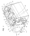
- Fig. 1 is a perspective view of the main portions of an embodiment of a cutting machine
- Fig. 2 is a longitudinal section view thereof
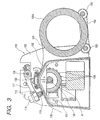
- Fig. 3 is a side view thereof
- Fig. 4 is a plan view thereof.
- reference character 101 designates a machine main body which includes two side plates 102 disposed respectively on the two sides thereof. Between the two side plates 102, there is formed a sheet guide surface 103 the central portion of which is formed in an angular shape. Next to the sheet guide surface 103, there is disposed a roller holder 104 on which there is held a sheet roller 105A with a cutting sheet 105 wound therearound. In the front and rear portions of the roller holder 104, there are disposed a pair of rollers 106 each so that the roller 105A can be rotated easily.
- a Y-axis shaft 108 On the sheet guide surface 103, there is disposed a Y-axis shaft 108.
- the Y-axis shaft 108 is rotatably supported by two bearing holes 109 respectively formed in the side plates 102 as well as penetrates the bearing holes 109 and projects externally therefrom.
- the two projecting ends 108a of the Y-axis shaft 108 are each formed in a D shape.
- the two ends of the Y-axis shaft 108 are respectively connected to the two ends of the sub-shaft 110 through connecting frames 112, 113.
- the connecting frames 112, 113 are each formed by bending a plate.
- the connecting frames 112, 113 respectively include bent portions 114 formed on the end portions thereof that are situated on the side of bearing holes 109 of the Y-axis shaft 108; and, setscrews 115 are threadedly engaged with the connecting frames 112, 113 through the bent portions 114 and the leading ends of the setscrews 115 are engaged with plane portions 116 respectively formed in the two end portions of the Y-axis shaft 108, thereby being able to prevent the connecting frames 112, 113 against play.
- the other-side ends of the connecting frames 112, 113 there are fixed the two ends of the sub-shaft 110, respectively. In this manner, the Y-axis shaft 108, sub-shaft 110 and connecting frames 112, 113 are fixed to one another and, as a whole, they are formed in a square-shaped frame assembly A1.
- a carriage 117 in such a manner that it is slidable along the Y-axis shaft 108.
- the carriage 117 is engaged with the Y-axis shaft 108 through a slide bearing or a slide bush and also, on the leading end portion of the carriage 117, there is mounted a cutter 119 through a cutter holder 118.
- the sub-shaft 110 penetrates the carriage 117, while the carriage 117 can be slid along the sub-shaft 110.
- the carriage 117 is operatively connected to a servo motor (not shown) through a wire 120.
- the sub-shaft 110 serves also as a sub-guide which guides the carriage 117 to move in the Y-axis direction.
- one end of the sub-shaft 110 is connected through an adjust frame 121 to a solenoid 122, and the sub-shaft 110 is also energized by a return spring 123 in such a manner that it is normally present on the upper end of the elongated hole 111.
- the solenoid 122 is turned on, the sub-shaft 110 is allowed to move downward along the elongated hole 111. Further, when the solenoid 122 is turned off, the sub-shaft 110 is moved upward by the return spring 123.
- the sub-shaft 110 can be moved up and down by an elevating device that consists of the solenoid 122 and return spring 123 and, with the elevating movement of the sub-shaft 110, the carriage 117 can be swung about the Y-axis shaft 108, so that the cutter 119 can be moved in the Z-axis direction.
- an elevating device that consists of the solenoid 122 and return spring 123 and, with the elevating movement of the sub-shaft 110, the carriage 117 can be swung about the Y-axis shaft 108, so that the cutter 119 can be moved in the Z-axis direction.
- a surface plate 124 which forms the seat guide surface 103 there are formed openings 125, and from these openings 125, there are exposed the outer peripheral surfaces of a sprocket 126 which is disposed in the interior portion of the machine main body 101.
- the sprocket 126 is rotatably supported on a support shaft al, and, on the outer peripheral surfaces 127, there are disposed projections 128 which can be engaged with the holes 107 formed on the two sides of the cutting sheet 105 in such a manner that the intervals of the projections 128 are equal to those of the holes 107.
- Inside of the openings 125 there are disposed sheet holders 130.
- the sprocket 126 is operatively connected to the servo motor (not shown) in such a manner that the former can be operated synchronously with the latter.
- the sprocket 126 is rotated to thereby move the cutting sheet 105 forwardly or backwardly in the X-axis direction along the sheet guide surface 103, the carriage 117 is moved in the Y-axis direction along the Y-axis shaft 108, and the sub-shaft 110 is moved up and down by the solenoid 122 and return spring 123 to thereby move up and down the cutter 119 in the Z-axis direction, so that the cutting sheet 105 can be cut out into a given shape.
- the elevating device for moving up and down the cutter 119 may be disposed only on one end of the sub-shaft 110. Even if the structure of the elevating device is simple, it can operate with sufficient accuracy.
- the elevating device is not limited to the solenoid and return spring but, of course, an actuator such as a moving coil or a motor can also be used.
- the elevating mechanism for moving up and down the cutter 119 can be simplified in structure as well as can be manufactured at a low cost.
- Fig. 5 is a perspective view of the main portions of a second embodiment of a cutting machine.
- Fig. 6 is a longitudinal section view of the cutting machine
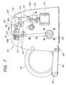
- Fig. 7 is a side view thereof
- Fig. 8 is a plan view thereof.
- reference character 201 designates a machine main body. Between the two side plates 202a, 202b of the machine main body 201, there is interposed a sheet guide surface 203, the central portion of which is formed in an angular shape, next to the sheet guide surface 203, there is disposed a roller holder 204 and, on the roller holder 204, there is placed a cutting sheet 205 which is wound in a roller shape. On the front and rear sides of the roller holder 204, there are disposed a pair of rollers 206 so as to be able to facilitate the rotation of the roll-shaped cutting sheet 5.
- a Y-axis shaft 208 On the upper side of the sheet guide surface 203, there is disposed a Y-axis shaft 208.
- the Y-axis shaft 208 is rotatably supported on the bearings 209a, 209b of the right and left side plates 202a, 202b, while the two ends 208a of the Y-axis shaft 208 respectively penetrating their associated bearings 209a, 209b and projecting outwardly on the side plates 202a, 202b are each formed so as to have a D-shaped section.
- a sub-shaft 210 which also penetrates elongated holes 211 respectively formed in their associated side plates 202a, 202b and projects outwardly from the side plates 202a, 202b.
- the two ends of the Y-axis shaft 208 and sub-shaft 210 are connected to each other through connecting frames 212, 213.
- the connecting frames 212, 213 are respectively formed by bending a plate, and setscrews 215 are threadedly engaged with their associated connecting frames 212, 213 from the bent portions 214 of the end portions of the connecting frames 212, 213 on the sides of bearings 209a, 209b of the Y-axis shaft 208, while the leading ends of the setscrews 215 are respectively engaged with plane portions 216 respectively formed in the two end portions of the Y-axis shaft 208 to thereby prevent the Y-axis shaft 208 against play.
- a carriage 217 in such a manner that it can be slid along the Y-axis shaft 208.
- the carriage 217 is engaged with the Y-axis shaft 208 through a slide bearing or a slide bush.
- On the leading end portion of the carriage 217 there is mounted a cutter 219 through a cutter holder 218.
- the sub-shaft 210 penetrates the carriage 217, while the carriage 217 can be slid along the sub-shaft 210.
- the carriage 217 is operatively connected to a servo motor (not shown) through a wire 220.
- the sub-shaft 210 serves also as a sub-guide which guides the carriage 217 to move in the Y-axis direction.
- One end of the sub-shaft 210 is connected through an adjust frame 221 to a solenoid 222, while the sub-shaft 210 is energized by a return spring 223 in such a manner that it is normally present on the upper ends of the elongated holes 211.
- the solenoid 222 is turned on, the sub-shaft 210 can be moved down along the elongated holes 211, and when the solenoid 222 is turned off, the sub-shaft 210 can be moved upward by the return spring 223.
- the sub-shaft 210 can be moved in the vertical direction by an elevating device which consists of the solenoid 222 and the return spring 223 and, with the vertical movement of the sub-shaft 210, the carriage 217 can be swung about the Y-axis shaft 208 in the vertical direction (Z-axis direction).
- the carriage 217 is swung downward, the cutting edge of the cutter 219 is contacted with the cutting sheet 205 set on the sheet guide surface 203 to thereby be able to cut the cutting sheet 205.
- openings 225 are formed on the two sides of a surface plate 224 which forms the sheet guide surface 203.
- the sprocket 226 is rotatably supported on a support shaft 228, and, on the outer peripheral surface 227 of the sprocket 226, there are disposed projections 229 which can be respectively engaged with their associated holes 207 formed on the two sides of the cutting sheet 205 in such a manner that. the intervals of the projections 229 are equal to those of the holes 207.
- a sheet holder 230 Inside of the openings 225, there is disposed a sheet holder 230.
- the sprocket 226 is operatively connected to a servo motor (not shown).
- the origin detecting sensor 236 is composed of a transmission-type photointerrupter and includes a light emitting section 236a and a light receiving section 236b.
- a control section (not shown) is able to judge that the carriage 217 has reached its origin position.
- the side frame 202a there is formed a vertically long opening 238 so that the leading end portion of the sensor lever 235 is able to penetrate the side frame 202a regardless of the vertical position of the carriage 217.
- the carriage 217 when the power is turned on, the carriage 217 moves along the Y-axis shaft 208 toward the side of the side frame 202a (origin side) in order to detect the origin position of the carriage 217 according to a control program.
- the control section confirms that the carriage 217 has reached the origin, and thus the control section controls the amount of movement of the carriage 217 in the Y-axis direction with the origin as the standard.
- the sub-shaft 217 is moved in the vertical direction using the solenoid 222 and return spring 223 to move the cutter up and down in the Z-axis direction, thereby being able to cut the cutting sheet 205 into a given shape.
- the carriage 217 can move in the Y-axis direction toward the side frame 202a, and the sensor lever 235 can penetrate the opening 238 of the side frame 202a and can moves to an upper position without interfering (colliding) with the photointerrupter 236.
- the photointerrupter 236 is fixed on the connecting frame 212, and the upper and lower positions of the photointerrupter 236 are moved in synchronization with the vertical movement of the carriage 217. Therefore, the leading end of the sensor lever 235 can always maintain a state in which it is able to move into the slit of the photointerrupter 236 (see Figs. 11 (a) and 11(b)).
- the carriage 217 and origin detecting sensor (photointerrupter) 236 are arranged on the frame assembly A2, the vertical movements of the carriage 217 and photointerrupter 236 are always synchronized with each other. Therefore, even if the cutting edge of the cutter has moved to the full extent of the effective width (the space between the holes 207 of both sides) of the cutting sheet 205 and, as shown in Fig. 10, the sensor lever 235 has moved through the side frame 202a, the leading end of the sensor lever 235 is always allowed to move into the slit between the light emitting part 236a and light receiving part 236b without interfering with the photointerrupter 236.
Landscapes
- Engineering & Computer Science (AREA)
- Life Sciences & Earth Sciences (AREA)
- Forests & Forestry (AREA)
- Mechanical Engineering (AREA)
- General Engineering & Computer Science (AREA)
- Control Of Cutting Processes (AREA)
Abstract
Description
Claims (7)
- A cutting machine for cutting a belt-shaped sheet into a given shape, comprising:a sheet feeder for moving the belt-shaped sheet in the X-axis direction;a Y-axis shaft disposed in the Y-axis direction above the cutting sheet;a carriage mounting a cutter on a leading end thereof and slidably disposed on said Y-axis shaft;a sub-shaft parallel to said Y-axis shaft and penetrating said carriage on the leading end side of said carriage;two connecting frames forming a frame assembly by connecting and fixing said Y-axis shaft and said sub-shaft to each other at each end of said Y-axis shaft and said sub-shaft; andan elevating device for moving up and down said sub-shaft to move the frame assembly up and down about said Y-axis shaft and to move the cutter up and down in the Z-axis direction with respect to the cutting sheet.
- The cutting machine according to Claim 1, wherein said elevating device comprises:wherein, when said solenoid is turned on, said sub-shaft is allowed to move downward, anda solenoid connected to an end of said sub-shaft; anda return spring energizing said sub-shaft upward in the Z-axis direction,
wherein, when said solenoid is turned off, said sub-shaft is moved upward by said return spring. - The cutting machine according to Claim 1, wherein said carriage further comprises a sensor lever projecting in a direction of an origin of said carriage, and
said cutting machine further comprising:an origin detecting sensor for detecting the sensor lever of said carriage when said carriage is moved in the direction of the origin, said origin detecting sensor disposed on one of said connecting frames,wherein said origin detecting sensor and said carriage are movable in the Z-axis direction in synchronization with each other. - The cutting machine according to Claim 3, wherein said elevating device comprises:wherein, when said solenoid is turned on, said sub-shaft is allowed to move downward, anda solenoid connected to an end of said sub-shaft; anda return spring energizing said sub-shaft upward in the Z-axis direction,
wherein, when said solenoid is turned off, said sub-shaft is moved upward by said return spring. - The cutting machine according to Claim 3, wherein said origin detecting sensor is a photointerrupter including a light emitting section and a light receiving section.
- A cutter elevating mechanism in a cutting machine for cutting a belt-shaped sheet moving in the X-axis direction into a given shape with a cutter moving in the Y- and Z-axis directions, said cutter elevating mechanism comprising:a Y-axis shaft disposed in the Y-axis direction above the cutting sheet;a carriage mounting a cutter on a leading end thereof and slidably disposed on said Y-axis shaft;a sub-shaft parallel to said Y-axis shaft and penetrating said carriage on the leading end side of said carriage;two connecting frames, each of said connecting frames connecting and fixing said Y-axis shaft and said sub-shaft to each other at each end of said Y-axis shaft and said sub-shaft; andan elevating device for moving up and down said sub-shaft to move the cutter up and down in the Z-axis direction with respect to the cutting sheet.
- A structure for an arrangement of an origin detecting sensor in a cutting machine for cutting a belt-shaped sheet moving in the X-axis direction into a given shape with a cutter moving in the Y- and Z-axis directions, said structure comprising:wherein said origin detecting sensor and said carriage are movable in the Z-axis direction in synchronization with each other.a Y-axis shaft disposed in the Y-axis direction above the cutting sheet;a carriage mounting a cutter on a leading end thereof and including a sensor lever projecting in a direction of an origin of said carriage, said carriage slidably disposed on said Y-axis shaft;a sub-shaft parallel to said Y-axis shaft and penetrating said carriage on the leading end side of said carriage;two connecting frames forming a frame assembly by connecting and fixing said Y-axis shaft and said sub-shaft to each other at each end of said Y-axis shaft and said sub-shaft;an origin detecting sensor for detecting the sensor lever of said carriage when said carriage is moved in the direction of the origin, said origin detecting sensor disposed on one of said connecting frames; andan elevating device for moving up and down said sub-shaft to move the frame assembly up and down about said Y-axis shaft and to move the cutter up and down in the Z-axis direction with respect to the cutting sheet,
Applications Claiming Priority (4)
| Application Number | Priority Date | Filing Date | Title |
|---|---|---|---|
| JP2000173653A JP4433572B2 (en) | 2000-06-09 | 2000-06-09 | Lifting mechanism of cutter in cutting machine |
| JP2000173653 | 2000-06-09 | ||
| JP2000173654 | 2000-06-09 | ||
| JP2000173654A JP4483033B2 (en) | 2000-06-09 | 2000-06-09 | Arrangement structure of origin detection sensor in cutting machine |
Publications (2)
| Publication Number | Publication Date |
|---|---|
| EP1162046A2 true EP1162046A2 (en) | 2001-12-12 |
| EP1162046A3 EP1162046A3 (en) | 2003-03-26 |
Family
ID=26593640
Family Applications (1)
| Application Number | Title | Priority Date | Filing Date |
|---|---|---|---|
| EP20010114006 Withdrawn EP1162046A3 (en) | 2000-06-09 | 2001-06-08 | X-Y axes cutting machine |
Country Status (3)
| Country | Link |
|---|---|
| US (1) | US6612215B2 (en) |
| EP (1) | EP1162046A3 (en) |
| TW (1) | TW512094B (en) |
Cited By (1)
| Publication number | Priority date | Publication date | Assignee | Title |
|---|---|---|---|---|
| US6694628B2 (en) | 2001-03-30 | 2004-02-24 | Max Co., Ltd. | Cutting machine |
Families Citing this family (9)
| Publication number | Priority date | Publication date | Assignee | Title |
|---|---|---|---|---|
| CA2323985A1 (en) * | 2000-10-19 | 2002-04-19 | Wilfred Koenders | Method and apparatus for cutting sheet metal |
| US6742428B2 (en) * | 2001-07-13 | 2004-06-01 | Xyron, Inc. | Cutter assembly for a master processing apparatus |
| DE502004003600D1 (en) * | 2004-01-12 | 2007-06-06 | Ray Technology Group B V | Device for storing and dispensing a cover film |
| US20070012146A1 (en) * | 2005-07-14 | 2007-01-18 | Robert Workman | Electronic paper cutting apparatus and method |
| US7930958B2 (en) | 2005-07-14 | 2011-04-26 | Provo Craft And Novelty, Inc. | Blade housing for electronic cutting apparatus |
| US20090000437A1 (en) * | 2005-07-14 | 2009-01-01 | Provo Craft And Novelty, Inc. | Methods for Cutting |
| US20110280999A1 (en) | 2009-12-23 | 2011-11-17 | Provo Craft And Novelty, Inc. | Foodstuff Crafting Apparatus, Components, Assembly, and Method for Utilizing the Same |
| KR101508167B1 (en) * | 2013-11-06 | 2015-04-07 | 한국타이어 주식회사 | Winding apparatus of carcass cutting process |
| USD854059S1 (en) * | 2017-09-08 | 2019-07-16 | Wazer Inc. | Cutting device |
Family Cites Families (14)
| Publication number | Priority date | Publication date | Assignee | Title |
|---|---|---|---|---|
| DE2931970C2 (en) | 1979-08-07 | 1982-10-21 | M.A.N.- Roland Druckmaschinen AG, 6050 Offenbach | Cutting device for longitudinal cutting of a paper web |
| JPS59175947A (en) * | 1983-03-22 | 1984-10-05 | Toshiba Mach Co Ltd | Transfer device |
| DE3729208C1 (en) * | 1987-08-29 | 1988-12-22 | Rotring Werke Riepe Kg | Cutting device |
| FR2647386A1 (en) | 1989-03-22 | 1990-11-30 | Isermatic France Sa | Device for marking out and partially cutting through the thickness of a protected adhesive multi-layer complex and machine making use thereof |
| US5262617A (en) * | 1990-08-17 | 1993-11-16 | Kabushiki Kaisha Tokyo Horaisha | Cutting means for fabrics and the like utilizing a heated cutting means mounted on a movable carriage |
| JPH04257367A (en) | 1991-02-06 | 1992-09-11 | Janome Sewing Mach Co Ltd | Mark cutting device and its control |
| DE4107801C2 (en) | 1991-03-11 | 1994-12-08 | Siemens Nixdorf Inf Syst | Record carrier cutting device for printing or copying machines |
| US5634388A (en) * | 1991-10-02 | 1997-06-03 | Kabushiki Kaisha Tokyo Horaisha | Mark cutting apparatus and method of controlling same |
| DE69711243T2 (en) | 1996-05-01 | 2002-10-31 | Copyer Co., Ltd. | AUFZEICHNUNGSTRÄGERSCHNEIDGERGÄT |
| JPH11309694A (en) | 1998-04-28 | 1999-11-09 | Brother Ind Ltd | Cutting blade orientation control device and its control method |
| JPH11333785A (en) | 1998-05-25 | 1999-12-07 | Brother Ind Ltd | Elevation adjustment device for cutting blade |
| JP2000015843A (en) * | 1998-06-30 | 2000-01-18 | Brother Ind Ltd | Printing equipment |
| FR2785338B1 (en) * | 1998-10-28 | 2001-08-10 | Aro | CYLINDER WITH ELASTIC DEVICE FOR RECALLING A WORKING PISTON ASSEMBLY IN NEUTRAL POSITION |
| DE20006995U1 (en) | 2000-04-15 | 2000-07-27 | Mathias Bäuerle GmbH, 78112 St Georgen | Device for processing continuous sheets or sheets of paper, cardboard or foil material |
-
2001
- 2001-06-08 US US09/875,199 patent/US6612215B2/en not_active Expired - Fee Related
- 2001-06-08 TW TW90113944A patent/TW512094B/en not_active IP Right Cessation
- 2001-06-08 EP EP20010114006 patent/EP1162046A3/en not_active Withdrawn
Cited By (1)
| Publication number | Priority date | Publication date | Assignee | Title |
|---|---|---|---|---|
| US6694628B2 (en) | 2001-03-30 | 2004-02-24 | Max Co., Ltd. | Cutting machine |
Also Published As
| Publication number | Publication date |
|---|---|
| US6612215B2 (en) | 2003-09-02 |
| US20010049989A1 (en) | 2001-12-13 |
| EP1162046A3 (en) | 2003-03-26 |
| TW512094B (en) | 2002-12-01 |
Similar Documents
| Publication | Publication Date | Title |
|---|---|---|
| US6612215B2 (en) | Cutting machine | |
| RU2000113093A (en) | BUTTERFLOW DEVICE WITH WIDTH CONTROL AND CENTERING FUNCTION | |
| US5794328A (en) | Automated window screen assembly apparatus | |
| US4089200A (en) | Gaging system | |
| KR20180103497A (en) | Cutting apparatus | |
| JP2014225591A (en) | Splicing device | |
| CA1046400A (en) | Record material cutting mechanism | |
| US4334674A (en) | Automatic feeding device for copying machines | |
| KR102191392B1 (en) | Flat knitting machine | |
| US4703630A (en) | Flat-bed knitting machine having a carriage displaceable into a position for servicing | |
| JPH03208594A (en) | Device for cutting single layer of tubular material web | |
| JP4433572B2 (en) | Lifting mechanism of cutter in cutting machine | |
| JP3729688B2 (en) | Elevator up / down end switch gap measuring device | |
| KR102374368B1 (en) | Appararus for automatically feeding tapes | |
| US4420107A (en) | Lead frame advance system | |
| JP4483033B2 (en) | Arrangement structure of origin detection sensor in cutting machine | |
| EP0486217A1 (en) | Cropping mechanism for surface mount placement machine | |
| JPH0714536B2 (en) | Assembly rebar bending device | |
| KR950011934B1 (en) | Automatic drawing machine | |
| JP2795204B2 (en) | Airtight material insertion machine | |
| JP7602982B2 (en) | Laser processing machine | |
| CN219583029U (en) | Cutting device | |
| JPH02218512A (en) | Work piece presence detecting method for cutting machine and its device | |
| JPH0725051B2 (en) | Limit switch device | |
| JP2020089952A (en) | Slitter cutting mechanism |
Legal Events
| Date | Code | Title | Description |
|---|---|---|---|
| PUAI | Public reference made under article 153(3) epc to a published international application that has entered the european phase |
Free format text: ORIGINAL CODE: 0009012 |
|
| AK | Designated contracting states |
Kind code of ref document: A2 Designated state(s): AT BE CH CY DE DK ES FI FR GB GR IE IT LI LU MC NL PT SE TR |
|
| AX | Request for extension of the european patent |
Free format text: AL;LT;LV;MK;RO;SI |
|
| RIC1 | Information provided on ipc code assigned before grant |
Free format text: 7B 26F 1/38 A, 7B 26D 5/02 B, 7B 26D 5/06 B |
|
| PUAL | Search report despatched |
Free format text: ORIGINAL CODE: 0009013 |
|
| AK | Designated contracting states |
Kind code of ref document: A3 Designated state(s): AT BE CH CY DE DK ES FI FR GB GR IE IT LI LU MC NL PT SE TR Designated state(s): AT BE CH CY DE DK ES FI FR GB GR IE IT LI LU MC NL PT SE TR |
|
| AX | Request for extension of the european patent |
Extension state: AL LT LV MK RO SI |
|
| AKX | Designation fees paid | ||
| REG | Reference to a national code |
Ref country code: DE Ref legal event code: 8566 |
|
| STAA | Information on the status of an ep patent application or granted ep patent |
Free format text: STATUS: THE APPLICATION IS DEEMED TO BE WITHDRAWN |
|
| 18D | Application deemed to be withdrawn |
Effective date: 20030927 |