EP1161702B1 - Halter für Gewebeproben - Google Patents
Halter für Gewebeproben Download PDFInfo
- Publication number
- EP1161702B1 EP1161702B1 EP20000907306 EP00907306A EP1161702B1 EP 1161702 B1 EP1161702 B1 EP 1161702B1 EP 20000907306 EP20000907306 EP 20000907306 EP 00907306 A EP00907306 A EP 00907306A EP 1161702 B1 EP1161702 B1 EP 1161702B1
- Authority
- EP
- European Patent Office
- Prior art keywords
- container
- specimen
- bag
- tissue
- tissue specimen
- Prior art date
- Legal status (The legal status is an assumption and is not a legal conclusion. Google has not performed a legal analysis and makes no representation as to the accuracy of the status listed.)
- Expired - Lifetime
Links
Images


Classifications
-
- G—PHYSICS
- G01—MEASURING; TESTING
- G01N—INVESTIGATING OR ANALYSING MATERIALS BY DETERMINING THEIR CHEMICAL OR PHYSICAL PROPERTIES
- G01N21/00—Investigating or analysing materials by the use of optical means, i.e. using sub-millimetre waves, infrared, visible or ultraviolet light
- G01N21/01—Arrangements or apparatus for facilitating the optical investigation
- G01N21/03—Cuvette constructions
- G01N21/0303—Optical path conditioning in cuvettes, e.g. windows; adapted optical elements or systems; path modifying or adjustment
-
- B—PERFORMING OPERATIONS; TRANSPORTING
- B01—PHYSICAL OR CHEMICAL PROCESSES OR APPARATUS IN GENERAL
- B01L—CHEMICAL OR PHYSICAL LABORATORY APPARATUS FOR GENERAL USE
- B01L3/00—Containers or dishes for laboratory use, e.g. laboratory glassware; Droppers
- B01L3/50—Containers for the purpose of retaining a material to be analysed, e.g. test tubes
- B01L3/508—Containers for the purpose of retaining a material to be analysed, e.g. test tubes rigid containers not provided for above
-
- G—PHYSICS
- G02—OPTICS
- G02B—OPTICAL ELEMENTS, SYSTEMS OR APPARATUS
- G02B21/00—Microscopes
- G02B21/0004—Microscopes specially adapted for specific applications
- G02B21/002—Scanning microscopes
- G02B21/0024—Confocal scanning microscopes (CSOMs) or confocal "macroscopes"; Accessories which are not restricted to use with CSOMs, e.g. sample holders
- G02B21/0028—Confocal scanning microscopes (CSOMs) or confocal "macroscopes"; Accessories which are not restricted to use with CSOMs, e.g. sample holders specially adapted for specific applications, e.g. for endoscopes, ophthalmoscopes, attachments to conventional microscopes
-
- G—PHYSICS
- G02—OPTICS
- G02B—OPTICAL ELEMENTS, SYSTEMS OR APPARATUS
- G02B21/00—Microscopes
- G02B21/34—Microscope slides, e.g. mounting specimens on microscope slides
-
- B—PERFORMING OPERATIONS; TRANSPORTING
- B01—PHYSICAL OR CHEMICAL PROCESSES OR APPARATUS IN GENERAL
- B01L—CHEMICAL OR PHYSICAL LABORATORY APPARATUS FOR GENERAL USE
- B01L2300/00—Additional constructional details
- B01L2300/04—Closures and closing means
- B01L2300/041—Connecting closures to device or container
- B01L2300/043—Hinged closures
-
- B—PERFORMING OPERATIONS; TRANSPORTING
- B01—PHYSICAL OR CHEMICAL PROCESSES OR APPARATUS IN GENERAL
- B01L—CHEMICAL OR PHYSICAL LABORATORY APPARATUS FOR GENERAL USE
- B01L2300/00—Additional constructional details
- B01L2300/06—Auxiliary integrated devices, integrated components
- B01L2300/0609—Holders integrated in container to position an object
-
- B—PERFORMING OPERATIONS; TRANSPORTING
- B01—PHYSICAL OR CHEMICAL PROCESSES OR APPARATUS IN GENERAL
- B01L—CHEMICAL OR PHYSICAL LABORATORY APPARATUS FOR GENERAL USE
- B01L2300/00—Additional constructional details
- B01L2300/06—Auxiliary integrated devices, integrated components
- B01L2300/0627—Sensor or part of a sensor is integrated
- B01L2300/0654—Lenses; Optical fibres
-
- B—PERFORMING OPERATIONS; TRANSPORTING
- B01—PHYSICAL OR CHEMICAL PROCESSES OR APPARATUS IN GENERAL
- B01L—CHEMICAL OR PHYSICAL LABORATORY APPARATUS FOR GENERAL USE
- B01L2300/00—Additional constructional details
- B01L2300/06—Auxiliary integrated devices, integrated components
- B01L2300/0672—Integrated piercing tool
-
- B—PERFORMING OPERATIONS; TRANSPORTING
- B01—PHYSICAL OR CHEMICAL PROCESSES OR APPARATUS IN GENERAL
- B01L—CHEMICAL OR PHYSICAL LABORATORY APPARATUS FOR GENERAL USE
- B01L2300/00—Additional constructional details
- B01L2300/08—Geometry, shape and general structure
- B01L2300/0809—Geometry, shape and general structure rectangular shaped
- B01L2300/0822—Slides
-
- B—PERFORMING OPERATIONS; TRANSPORTING
- B01—PHYSICAL OR CHEMICAL PROCESSES OR APPARATUS IN GENERAL
- B01L—CHEMICAL OR PHYSICAL LABORATORY APPARATUS FOR GENERAL USE
- B01L2400/00—Moving or stopping fluids
- B01L2400/06—Valves, specific forms thereof
- B01L2400/0677—Valves, specific forms thereof phase change valves; Meltable, freezing, dissolvable plugs; Destructible barriers
- B01L2400/0683—Valves, specific forms thereof phase change valves; Meltable, freezing, dissolvable plugs; Destructible barriers mechanically breaking a wall or membrane within a channel or chamber
-
- G—PHYSICS
- G01—MEASURING; TESTING
- G01N—INVESTIGATING OR ANALYSING MATERIALS BY DETERMINING THEIR CHEMICAL OR PHYSICAL PROPERTIES
- G01N1/00—Sampling; Preparing specimens for investigation
- G01N1/28—Preparing specimens for investigation including physical details of (bio-)chemical methods covered elsewhere, e.g. G01N33/50, C12Q
- G01N1/36—Embedding or analogous mounting of samples
-
- G—PHYSICS
- G01—MEASURING; TESTING
- G01N—INVESTIGATING OR ANALYSING MATERIALS BY DETERMINING THEIR CHEMICAL OR PHYSICAL PROPERTIES
- G01N21/00—Investigating or analysing materials by the use of optical means, i.e. using sub-millimetre waves, infrared, visible or ultraviolet light
- G01N21/01—Arrangements or apparatus for facilitating the optical investigation
- G01N21/03—Cuvette constructions
- G01N2021/0339—Holders for solids, powders
-
- G—PHYSICS
- G01—MEASURING; TESTING
- G01N—INVESTIGATING OR ANALYSING MATERIALS BY DETERMINING THEIR CHEMICAL OR PHYSICAL PROPERTIES
- G01N21/00—Investigating or analysing materials by the use of optical means, i.e. using sub-millimetre waves, infrared, visible or ultraviolet light
- G01N21/01—Arrangements or apparatus for facilitating the optical investigation
- G01N21/03—Cuvette constructions
- G01N2021/0342—Solid sample being immersed, e.g. equiindex fluid
-
- G—PHYSICS
- G01—MEASURING; TESTING
- G01N—INVESTIGATING OR ANALYSING MATERIALS BY DETERMINING THEIR CHEMICAL OR PHYSICAL PROPERTIES
- G01N21/00—Investigating or analysing materials by the use of optical means, i.e. using sub-millimetre waves, infrared, visible or ultraviolet light
- G01N21/01—Arrangements or apparatus for facilitating the optical investigation
- G01N21/03—Cuvette constructions
- G01N2021/0364—Cuvette constructions flexible, compressible
Definitions
- the present invention relates to a tissue specimen holder or tray for use in microscopy and particularly in laser scanning confocal microscopy for imaging sections of surgically excised specimens.
- the invention is especially suitable for providing a tissue tray which aids in the imaging of a wide variety of tissue samples which may be excised tissues or biopsies of various tissues, such as liver, kidney, cervix, et cetera.
- the tray provided by the invention may be used to contain the specimen for short term or long term storage or to transport the tissue for additional processing.
- the tray may be disposable after use.
- the tray contains and also has associated therewith index matching liquids. The tray facilitates the use of such liquids without messy operations and without adversely affecting imaging (imparting distortion to the image because of the presence of the index matching liquids).
- the confocal laser scanning microscope imaging systems having objective lenses which are capable of forming images of different sections having different orientations within a specimen may be of the type described in allowed U.S. Patent application serial number 08/683,607 filed July 15, 1996 in the name of R. Rox Anderson et al. , now U.S. Patent No. 5,880,880, issued March 9, 1999 , and U.S. Patent 5,788,639, filed in the names of James Zavislan and Jay Eastman and issued August 4, 1998 .
- a specimen holder in accordance with the invention includes a container having a cover and a window through which an optical beam passes into a specimen disposed in the container over the window.
- the container may be in the form of a specimen tray.
- the specimen is preferably held in place by clamps which may be automatically applied when the cover of the container is closed.
- the container includes an immersion liquid which closely matches the index of the tissue. Matching may be to the average index at the surface of the tissue which interfaces with the window.
- the tissue surface may be corrugated due to natural or surgically produced surface texture. Such corrugation may alter the wavefront of the beam (make the wavefront depart from a section of a sphere) which enters the tissue and is focused in the tissue section of interest.
- the distortion due to such variations is reduced in accordance with the invention by virtue of minimizing the variation of optical path lengths, notwithstanding that the section at which the beam is focused may be at the surface of the tissue or within the tissue (for example a distance of up to approximately 3mm from the surface) by use of immersion liquids and coupling liquids and other transmissive elements, including the window, through which the imaging beam passes.
- the coupling medium is contained in a bag outside the container and facing the window.
- the bag is made of compliant transmissive material such as a polymer, for example polyethylene, but is of a minimum thickness so as not to have any material effect on the optical path through the bag.
- the bag contains a liquid coupling medium.
- Mounted on the bag is a stabilizing plate of transmissive material.
- the plate is opposed to the window, and preferably contains a lock-in unit such as a magnet or magnetic ring which is received in a notch at the top of a barrel containing the objective lens of the imaging system.
- the objective lens and the tray is supported on a fixture which is mounted on a common structure with the objective lens via a translation mechanism, which moves the fixture and the container in nominally orthogonal directions, one of which is along the optical axis of the lens.
- the index of the coupling medium is preferably the same as the index of the immersion liquid.
- the tray has a passageway which is pierced by a protrusion on the cover of the tray so as to allow the coupling liquid to fill the tray and provide the immersion liquid.
- the stabilizing coupling of the plate to the objective lens prevents tilting and maintains the plate perpendicular to the optical axis notwithstanding of motion of the container so as to bring sections of the specimen of interest into focus and to scan the specimen in the plane of the section.
- the difference between the index of refraction of the immersion liquid and the average index of refraction of the tissue at its surface, multiplied by the height between the peaks of the hills and bottoms of the valleys of the corrugations is selected to be equal or less than a quarter wavelength at the wavelength of the laser beam used for imaging.
- the index matching fluids can be selected in the preparation of the tray for the particular tissue to be imaged.
- the thickness and index of the window and the plate may be varied depending upon the type of tissue in the tray in order to reduce spherical aberration for the objective lens used in the imaging system.
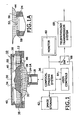
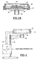
- FIGS. 1, 1A , 1B, 2 and 7 there is shown a tissue holder or tray 10 mounted on a support platform 12.
- the support platform 12 is moveable by a translation mechanism 14 which is mounted on a stand 16 which holds an objective lens assembly 18 in a nominally fixed position.
- the platform 12, translation mechanism 14 and stand 16 provide a tray support fixture which can receive various trays.
- the lens assembly 18 includes a lens barrel 20 and a lens 22 mounted within the barrel.
- the upper end of the barrel has an annular notch 24 in which a portion of the tray 10 is received and locked, as will be discussed in greater detail below.
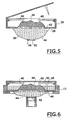
- the tissue tray or holder 10 is an assembly having a generally open specimen container or box with a plate providing a base 26, sidewalls 28 and a cover 30, which may be hinged to one of the side walls.
- the shape of the box is shown as rectangular but it may be circular or oblong.
- the base has an opening containing a window 32 of transparent material. The thickness and refractive index of this window is selected to accommodate the design of the lens 18 and the index of refraction of the tissue specimen 34.
- the specimen may be surgically excised.
- a compliant bag 44 of thin, optically transparent material is attached to the underside of the base 26 of the tray 10.
- This bag is initially filled with an optical coupling medium which may also provided an immersion medium for the specimen 34.
- the specimen 34 is placed on the window 32 as shown in FIG. 3 .
- Clamping mechanisms 40 are then used to hold down the tissue specimen on the window for viewing, as shown in FIG. 5 .
- the mechanisms are shown engaging the specimen 34 in FIG. 5 , but may automatically engage the specimen when the cover is closed, as shown in connection with FIG. 4 .
- a pin 50 carried on the cover, pierces a plug 45 in an opening 46 which provides a passageway for the flow of the coupling medium into the tray through the pierced opening 46.
- a transparent stabilizing plate 52 which is attached to the bag 44 in a location near the bottom of the bag opposite to the window 32, is captured in the notch 24 at the upper end of the lens barrel.
- the relative heights of the platform 12 and the lens barrel 24, both of which are supported in the fixture 16, is such that the bag 44 is compressed by the lens barrel and the shape thereof changes from the shape shown in FIG. 5 to the shape shown in FIG. 6 .
- the liquid optical coupling medium 39 flows through the hole 46 and encompasses the specimen.
- the coupling liquid then serves as the immersion liquid.
- the tray may be filled with the immersion liquid, and, when the plug is pierced, the immersion liquid flows into the bag.
- the bag and tray are independently filled. When plug 45 is opened the fluids can mix.
- the height of the liquid above the lens and above the base depends upon the relative position of the tray and may vary as the tray is moved to select the focus in the section of the specimen to be imaged. See FIG. 1B .
- the configuration of the bag also changes as the tray moves with respect to the objective lens 18 to scan the section.
- the objective lens 18 may be a generic lens which is corrected for spherical aberrations for a cover slip of certain index N T and thickness T.
- the spherical aberration present in the objective lens is equal and opposite the spherical aberration introduced by the cover media or slip.
- the cover medium includes plate 52, coupling medium 39, and window 32.
- the relationships when the plate is liquid are similar. See Warren Smith, Optical Engineering, pages 96-99 published by McGraw Hill, (1990 ) for further information on the equations given above.
- Aberration is introduced by the specimen and particularly by the surface texture of the specimen in the optical path (along the axis of the lens 18).
- a laser beam from a confocal imaging system 36 passes through the lens along the optical path and is focused in the specimen.
- the tissue defines a corrugated surface as shown in FIG. 8 .
- There is index variation between the tissue surface and the window 32 which may be accommodated in part, by a selection of the index and thickness in the direction of the beam (along the optical axis) through the window 32.
- the other indices of refraction of the elements in the beam path are also taken into account in determining the thickness and index of either the window 32, plate 52, or both.
- the primary determinative of the index and thickness of the window 32 is the index of the tissue of the specimen 34.
- the index and thickness of the window 32 will depend upon the type of specimen being imaged. Different trays 10 are provided for different types of specimens (kidney, liver, cervix, et cetera) and each will have a somewhat different window thickness and index in order to reduce spherical aberration.
- An immersion liquid 38 having an index which generally matches the average index of the tissue of the specimen 34 is contained in the tray.
- This liquid may serve also as a tissue preservative or fixative.
- the clamp mechanism 40 which is illustrated has hooked or barbed fingers which are hinged to the sidewalls 28 at spaced locations.
- the mechanisms include springs 42 which provide over center locks, such that when the fingers are pressed down beyond their axis of rotation, they are held down by the springs 42.
- Other clamping mechanisms may be used such as meshes or a membrane overlay or a permeable or perforated bag. Fiducial marks, which can be visualized or imaged, may be provided in the case of meshes or membranes. The use of a membrane or mesh may be preferable since the specimen 34 may be moved under the membrane.
- the membrane specimen tray or cassette is the subject matter of a companion application filed concurrently herewith in the name of Bill Fox, et al. now US. Patent No. 6,411,434 . Further information as to the use of the markings on the clamping mechanism (the mesh or membrane) to mark locations of the image tissue is contained in a co-pending International Patent Application No. PCT/US99/21116 , and U.S. Patent Application, filed in the names of Roger J. Greenwald and James M. Zavislan, serial number 60/100,176, filed September 14,1998 now U.S. Patent No. 6,745,067 .
- the purpose of the clamps is to keep the tissue stationary during examination and also provide a means to lightly compress the tissue surface against the window. Alternatively, the clamps may provide tension to pull the tissue surface taut. Holding the tissue with either compression normal to the window or in tension parallel to the window (or both) tends to reduce the surface texture, or corrugation, peak to valley depth.
- the thin compliant bag 44 is attached to the base 26 and encompasses the window 32 and the initially plugged opening 46.
- the bag is filled with the optical coupling medium 39, which may have an index selected in order to reduce image distortion due to the corrugations formed by the texture surface of the specimen 34 via which the optical imaging beam passes.
- the coupling liquid is the same as the immersion liquid 38 and the coupling liquid may flow through the opening 46 which may initially have a plug 45 and be plugged and then opened by the pin 50 carried by the cover 30, when the cover is closed as shown in FIG. 6 .
- the stabilizing plate 52 is attached to the bag 44 opposite to the window 32.
- This plate has an index of refraction and thickness which is taken into account in selecting the thickness and index of the window 32.
- a magnet or magnetic ring 56 surrounds the plate 52. See FIG. 1A .
- the plate 52 may be held by fusing, welding, cementing, friction or screw fit into the ring 56.
- the ring is permanently attached, as by a fused or cemented connection, to the bag 44, or to an opening in the bag.
- the diameter of the ring 52 is sized to fit into a notch 58 at the upper end of the barrel of the objective lens.
- the barrel may be made of magnetic material so as to lock the bag 44 in place on the assembly of the objective lens 18.
- the attachment is removable since the hold down force is magnetic. Other removable or releasable lock in mechanisms, such as snaps, may be used.
- the plate 52 may be curved or of a meniscus shape to provide optical power added to the power of the objective,
- the confocal imaging system 36 may be of the type described in the above referenced Anderson and Zavislan patents. Imaging systems using two-photon microscopy or optical coherence tomography may also be used. See Denk et al., U.S. Pat. No. 5,034,613 and Schmitt et al., Proc. SPIE, volume 1889 (1993 ).
- a monitor or display 60 which provides a display of the image of the section.
- the image may also be stored digitally in memory shown as image storage 62.
- the location of the section being imaged is obtained by user controls 64 which may provide signals for actuating drive motors or other actuators in the translation mechanism 14 which selects the section to be imaged and can scan the section.
- the translator stage may be manually controlled by the use of micrometers.
- the image storage 62 or the imaging system may be connected through a switch 66 to a telepathology transmission system 68 which transmits the image to a remote location.
- a telepathology transmission system 68 is the subject of U.S. Patent 5,836,877 issued November 17, 1988 to J. Zavislan .
- the lens 18 may focus the beam at the surface or within the specimen by moving the support 12 thereby varying the distance between the lens and the tray.
- the thickness along that axis of the coupling and medium 39 varies in an opposite sense. This keeps the optical path constant, even though the section may be well within the specimen.
- This inverse relationship of bag thickness to focus depth is in a direction to compensate for aberration due to physical length variations between the lens and the section of the medium being imaged.
- the corrugations due to the surface texture of the specimen 34 creates corrugations having a depth (h) (from the apex of the corrugation peaks to the bottom of the valleys of the corrugations) which may be approximately 200 microns in length.
- the index of refraction of the tissue is n T
- the index of refraction of the immersion fluid which fills the corrugations providing the surface texture of the specimen 34, have an index n I .
- the beam is focused at a focus f in the section to be imaged.
- the wavefront which may be spherical, can be distorted due to an optical path difference ⁇ imprinted on the wavefront which converges to the focus F.
- This path difference is a function of the product of the corrugation height h and the difference between n T and n I .
- the use of the index matching fluid reduces the optical path difference so that the imprint is minimized.
- the optical path difference ⁇ is shown enlarged at 63 in FIG. 8 .
- This optical path difference may also be viewed as the wavefront which is propagating to the focus F.
- This wavefront may be spherical and part of a sphere as shown at 68 prior to passing through corrugations at the surface of the specimen 34.
- the immersion medium 38 is selected for the tissue type which is placed in the tray and substantially corrects for optical distortion due to the surface texture of the specimen.
- the tray and the specimen are prepared by placing the tissue therein, and positioning the tissue.
- the tray is then placed in the support 12 and the magnet lock in 56 connects the tray to the objective lens.
- the lid is closed, piercing the membrane or plug covering opening 46, allowing coupling media to flow upwardly from the bag 44 attached to the bottom portion of tray 10.
- the tray may be filled with the immersion liquid before closing the lid and flows down into bag 44 upon lid closing.
- the beam is focused at the section and scanned across the section so as to obtain images of that section.
- a bar code, or other indicia may be applied to the tray 10, as on its cover or a side wall for identification and tracking of the specimen, which is especially useful when the tray and specimen are archived (stored for later examination or other use).
Claims (13)
- Probenhalter (10), umfassend:einen Behälter mit einer Abdeckung (30), der mit einer Innenseite versehen ist,auf die eine Gewebeprobe (34) angeordnet ist, ein Fenster (32) in dem Behälter, das wenigstens einen Teil der Innenseite bildet, durch die ein Lichtstrahl zum Abbilden von wenigstens einem Abschnitt der Gewebeprobe (34) oder einer Fläche der Gewebeprobe geht,Mittel (40) zum Festklemmen der Gewebeprobe (34) auf das Fenster(32),eine nachgiebige Tasche (44), die an der Außenseite des Behälters gegenüber der Innenseite, auf der die Gewebeprobe (34) angeordnet ist, befestigt ist,ein Immersionsmedium (38), das mit der Gewebeprobe (34) angeordnet ist undeinen Brechungsindex aufweist, der im Wesentlichen mit dem Brechungsindex der Gewebeprobe (34) übereinstimmt, und/oderein Kopplungsmedium (39) in der Tasche, undeinen Durchgang (46) zwischen der Tasche (44) und dem Behälter, der durch einen Vorsprung (50) auf der Abdeckung (30) beim Schließen der Abdeckung (30) durchstoßen und geöffnet wird, wobei der Durchgang (46) nach dem Öffnen das Fließen des Kopplungsmediums (39) aus der Tasche (44) in den Behälter und/oder das Fließen des Immersionsmediums (38) aus dem Behälter in die Tasche (44) erlaubt.
- Probenhalter (10) nach Anspruch 1, wobei der Brechungsindex des Kopplungsmediums (39) gleich dem Brechungsindex des Immersionsmediums (38) ist, oder weiterhin ein bildgebendes System mit wenigstens einer Objektivlinse (18) umfasst, die einen optischen Strahl in dem Abschnitt der abzubildenden Gewebeprobe (34) fokussiert, wobei die wechselseitigen Anordnungen der nachgiebigen Tasche (44) und der Linse in engem Zusammenhang stehen.
- Probenhalter (10) nach Anspruch 2, der in Bezug auf die Definition eines bildgebenden Systems eine Halterung (12), auf der der Halter (10) angeordnet ist, eine Befestigungsvorrichtung, die die Halterung (12) mit der Objektivlinse (18) verbindet und Mittel zum Verändern der relativen Anordnungen der Halterung (12) und des Halters (10) bezüglich der Objektivlinse (18) umfasst, wobei die Objektivlinse (18) fest angebracht ist und das Mittel das Bewegen der Halterung (12) in Richtung entlang einer optischen Achse der Linse (22) und in zueinander und zur optischen Achse senkrechten Richtungen bewirkt, oder der weiterhin eine transparente Platte zur Stabilisierung (52), die auf der Tasche (44) gegenüber dem Fenster (32) befestigt ist, und Mittel zum lösbaren Einbauen der Platte (52) und der Objektivlinse (18) umfasst, oder wobei der Behälter einschließlich der Immersionsflüssigkeit (38) und der Tasche (44) von der Objektivlinse (18) abgenommen und zum Beseitigen der Gewebeprobe (34) nach dem Abbilden von der Halterung (12) entfernt werden kann.
- Probenhalter (10) nach Anspruch 1, wobei der Behälter einen Kanal aufweist, der geöffnet werden kann und den Durchgang (46) bildet und durch den ein flüssiges Medium entweder aus dem Behälter in die Tasche (44) oder aus der Tasche (44) in den Behälter unter Bereitstellung des Immersionsmediums (38) und des Kopplungsmediums (39) fließt.
- Probenhalter (10) nach Anspruch 1, weiterhin umfassend:eine auf das durch das Fenster (32) hindurch untersuchte Gewebe gerichtete Optik.
- Probenhalter (10) nach Anspruch 5, wobei die Tasche (44) zwischen dem Behälter und der Optik liegt, ein Medium zwischen dem Behälter und der Optik darstellt und die Optik optisch mit dem Behälter koppelt, oder der weiterhin an dem Behälter angebrachte Vermerke zur Identifikation des darin angeordneten untersuchten Gewebes umfasst.
- Probenhalter (10) nach Anspruch 1, weiterhin umfassend Mittel zur Abbildung der Gewebeprobe (34) durch das Fenster (32) hindurch, wenn sich die Gewebeprobe (34) auf dem Fenster (32) befindet.
- Probenhalter (10) nach Anspruch 7, wobei die Tasche (44) für die bildgebenden Mittel optisch transparent ist.
- Probenhalter (10) nach Anspruch 1, wobei das Immersionsmedium und das Kopplungsmedium Brechungsindizes aufweisen, die im Wesentlichen miteinander übereinstimmen.
- Probenhalter (10) nach Anspruch 7, wobei die bildgebenden Mittel eine Objektivlinse (18) aufweisen, die einen Lichtstrahl durch das Fenster (32) auf die Gewebeprobe (34) fokussiert und das zu den bildgebenden Mitteln zurückkehrende Licht einen Abschnitt der Gewebeprobe (34) darstellt, oder wobei die bildgebenden Mittel ein Konfokalmikroskop sind, oder wobei die bildgebenden Mittel entweder auf dem Prinzip der optischen Kohärenztomographie oder der Zwei-Photonen-Mikroskopie arbeiten, oder wobei die Gewebeprobe (34) wenigstens eine zu dem Einsatz (10) hin im Wesentlichen ebene Fläche aufweist.
- Probenhalter (10) nach einem der vorhergehenden Ansprüche, wobei die Mittel (40) zum Klemmen entweder federvorgespannte Finger, ein Netz oder eine Membran aufweisen, die die Gewebeprobe (34) auf dem Fenster (32) halten können.
- Probenhalter (10) nach einem der vorhergehenden Ansprüche, wobei das Immersionsmedium (38) so ausgewählt ist, dass es eine optische Verzerrung auf Grund der Oberflächentextur der Gewebeprobe (34) im Wesentlichen korrigiert.
- Verfahren zur Abbildung von untersuchtem Gewebe, umfassend:das Bereitstellen eines Behälters mit einer Abdeckung (30) und das Bereitstellen einer Innenseite zum Anordnen der Gewebeprobe (34);das Festklemmen der Gewebeprobe (34) auf der Innenseite des Behälters;das Abbilden von wenigstens einem Abschnitt der Gewebeprobe (34) durch den Behälter hindurch;das Anordnen einer Tasche (44) an der Außenseite des Behälters und gegenüber der Innenseite, wobei der bildgebende Schritt die Gewebeprobe (34) durch wenigstens den Behälter und die optische Kopplungsflüssigkeit (39) der Tasche (44) hindurch abbildet; unddas Bereitstellen eines flüssigen Immersionsmediums (38) in dem Behälter, das einen im Wesentlichen mit der Gewebeprobe (34) übereinstimmenden Brechungsindex aufweist, und/oder das Bereitstellen eines Kopplungsmediums (39) in der Tasche;das Bereitstellen eines Durchgangs zwischen der Tasche (44) und dem Behälter, der beim Schließen der Abdeckung durch einen Vorsprung (50) auf der Abdeckung (30) durchstoßen und geöffnet wird, damit das Kopplungsmedium (39) aus der Tasche (44) in den Behälter und/oder das Immersionsmedium (38) aus dem Behälter in die Tasche (44) fließen kann wenn der Durchgang (46) geöffnet ist.
Applications Claiming Priority (3)
| Application Number | Priority Date | Filing Date | Title |
|---|---|---|---|
| US12047099P | 1999-02-17 | 1999-02-17 | |
| US120470P | 1999-02-17 | ||
| PCT/US2000/004128 WO2000049447A1 (en) | 1999-02-17 | 2000-02-17 | Tissue specimen holder |
Publications (3)
| Publication Number | Publication Date |
|---|---|
| EP1161702A1 EP1161702A1 (de) | 2001-12-12 |
| EP1161702A4 EP1161702A4 (de) | 2007-10-24 |
| EP1161702B1 true EP1161702B1 (de) | 2014-07-23 |
Family
ID=22390502
Family Applications (1)
| Application Number | Title | Priority Date | Filing Date |
|---|---|---|---|
| EP20000907306 Expired - Lifetime EP1161702B1 (de) | 1999-02-17 | 2000-02-17 | Halter für Gewebeproben |
Country Status (6)
| Country | Link |
|---|---|
| US (3) | US6330106B1 (de) |
| EP (1) | EP1161702B1 (de) |
| JP (1) | JP2002537579A (de) |
| AU (1) | AU2882800A (de) |
| ES (1) | ES2520140T3 (de) |
| WO (1) | WO2000049447A1 (de) |
Cited By (1)
| Publication number | Priority date | Publication date | Assignee | Title |
|---|---|---|---|---|
| DE102015204134A1 (de) * | 2015-03-09 | 2016-09-15 | Carl Zeiss Microscopy Gmbh | Mikroskop zur sphärisch korrigierten Abbildung dreidimensionaler Objekte |
Families Citing this family (61)
| Publication number | Priority date | Publication date | Assignee | Title |
|---|---|---|---|---|
| US7227630B1 (en) | 1998-09-14 | 2007-06-05 | Lucid, Inc. | Imaging of surgical biopsies |
| AU5920899A (en) | 1998-09-14 | 2000-04-03 | Lucid, Inc. | Imaging of surgical biopsies |
| JP4564664B2 (ja) | 1999-02-17 | 2010-10-20 | ルーシド インコーポレーテッド | 保持された組織検体の光学的薄断片を形成するカセット |
| JP2002537579A (ja) * | 1999-02-17 | 2002-11-05 | ルーシド インコーポレーテッド | 組織検体ホルダ |
| GB2360842B (en) * | 2000-03-31 | 2002-06-26 | Toshiba Res Europ Ltd | An apparatus and method for investigating a sample |
| US7194118B1 (en) | 2000-11-10 | 2007-03-20 | Lucid, Inc. | System for optically sectioning and mapping surgically excised tissue |
| WO2003041143A1 (fr) * | 2001-11-09 | 2003-05-15 | Semiconductor Energy Laboratory Co., Ltd. | Dispositif de traitement par faisceau laser et dispositif semi-conducteur |
| US20070255169A1 (en) * | 2001-11-19 | 2007-11-01 | Dune Medical Devices Ltd. | Clean margin assessment tool |
| US20040133112A1 (en) * | 2002-03-08 | 2004-07-08 | Milind Rajadhyaksha | System and method for macroscopic and confocal imaging of tissue |
| US7197355B2 (en) * | 2002-04-19 | 2007-03-27 | Visiongate, Inc. | Variable-motion optical tomography of small objects |
| DE10239739B4 (de) * | 2002-08-29 | 2006-05-11 | Leica Mikrosysteme Gmbh | Vorrichtung und Verfahren zur Durchführung von immunologischen Markierungstechniken für Gewebedünnschnitte |
| KR20050114615A (ko) * | 2003-02-04 | 2005-12-06 | 제테틱 인스티튜트 | 비공초점, 공초점 및 간섭 공초점 현미경 검사시 기판-매질계면에서의 굴절률 불일치 효과 보상 |
| US7026259B2 (en) * | 2004-01-21 | 2006-04-11 | International Business Machines Corporation | Liquid-filled balloons for immersion lithography |
| JP4587960B2 (ja) * | 2004-02-16 | 2010-11-24 | オリンパス株式会社 | 液浸対物レンズ及び液浸媒質の保持機構 |
| JP4731847B2 (ja) * | 2004-07-15 | 2011-07-27 | オリンパス株式会社 | ペトリディッシュ、チャンバー装置、光学顕微鏡観察方法及び試料分析方法 |
| US7864996B2 (en) * | 2006-02-17 | 2011-01-04 | Lucid, Inc. | System for macroscopic and confocal imaging of tissue |
| US8260401B2 (en) | 2006-07-26 | 2012-09-04 | University Of Rochester | Non-invasive in-vivo imaging of mechanoreceptors in skin using confocal microscopy |
| US7973925B2 (en) * | 2007-02-06 | 2011-07-05 | C8 Medisensors Inc. | Apparatus for stabilizing mechanical, thermal, and optical properties and for reducing the fluorescence of biological samples for optical evaluation |
| US20100196446A1 (en) | 2007-07-10 | 2010-08-05 | Morteza Gharib | Drug delivery and substance transfer facilitated by nano-enhanced device having aligned carbon nanotubes protruding from device surface |
| US20090046359A1 (en) * | 2007-08-14 | 2009-02-19 | Nikon Corporation | Microscope |
| WO2009064380A2 (en) | 2007-11-09 | 2009-05-22 | California Institute Of Technology | Fabrication of anchored carbon nanotube array devices for integrated light collection and energy conversion |
| DE202008010411U1 (de) * | 2008-05-31 | 2008-10-16 | Klinika Medical Gmbh | Anordnung zum Transport und/oder zur Aufbewahrung einer menschlichen oder tierischen Gewebeprobe |
| WO2010021744A1 (en) * | 2008-08-21 | 2010-02-25 | California Institute Of Technology | Microscope coupled tissue sectioning system |
| JP5638793B2 (ja) * | 2009-12-03 | 2014-12-10 | オリンパス株式会社 | 顕微鏡装置 |
| WO2011127207A2 (en) | 2010-04-07 | 2011-10-13 | California Institute Of Technology | Simple method for producing superhydrophobic carbon nanotube array |
| WO2012079066A2 (en) | 2010-12-10 | 2012-06-14 | California Institute Of Technology | Method for producing graphene oxide with tunable gap |
| US8976507B2 (en) | 2011-03-29 | 2015-03-10 | California Institute Of Technology | Method to increase the capacitance of electrochemical carbon nanotube capacitors by conformal deposition of nanoparticles |
| US8411265B2 (en) * | 2011-06-14 | 2013-04-02 | C8 Medisensors Inc. | Apparatus for stabilizing mechanical, thermal, and optical properties and for reducing the fluorescence of biological samples for optical evaluation |
| WO2013090844A1 (en) | 2011-12-14 | 2013-06-20 | California Institute Of Technology | Sharp tip carbon nanotube microneedle devices and their fabrication |
| US9341551B2 (en) * | 2012-01-10 | 2016-05-17 | Uc-Care Ltd. | Device and method for handling biological tissues |
| ES2925001T3 (es) * | 2012-01-16 | 2022-10-13 | Mavig Gmbh | Método para preparar una muestra de tejido |
| CN104254767B (zh) * | 2012-02-26 | 2016-10-26 | 克力博成像诊断股份有限公司 | 用于光学切片显微镜的组织样本工作台 |
| WO2014022314A1 (en) | 2012-07-30 | 2014-02-06 | California Institute Of Technology | Nano tri-carbon composite systems and manufacture |
| WO2014085911A1 (en) | 2012-12-05 | 2014-06-12 | Tornado Medical Systems, Inc. | System and method for wide field oct imaging |
| US10502666B2 (en) | 2013-02-06 | 2019-12-10 | Alentic Microscience Inc. | Sample processing improvements for quantitative microscopy |
| AT16689U1 (de) * | 2013-05-10 | 2020-04-15 | European Molecular Biology Laboratory | Mikroskopmodul zum Abbilden einer Probe |
| EP2801855B1 (de) | 2013-05-10 | 2019-07-17 | European Molecular Biology Laboratory | Mikroskopmodul zur Abbildung einer Probe |
| DE102013210269B8 (de) * | 2013-06-03 | 2015-01-29 | Laser Zentrum Hannover E.V. | Vorrichtung und Verfahren zur Untersuchung von Proben in einer Flüssigkeit |
| CA2953620C (en) | 2013-06-26 | 2020-08-25 | Alentic Microscience Inc. | Sample processing improvements for microscopy |
| EP2873997A1 (de) * | 2013-11-15 | 2015-05-20 | Eppendorf Ag | Zählkammereinrichtung, Positioniereinrichtung für diese, Zählvorrichtung und Verfahren zur Zählung von mikroskopischen Partikeln |
| WO2015171665A1 (en) | 2014-05-05 | 2015-11-12 | Caliber Imaging & Diagnostics, Inc. | System and method for mapping the locations of captured confocal images of a lesion in skin tissue |
| JP2016130673A (ja) * | 2015-01-14 | 2016-07-21 | オリンパス株式会社 | 顕微鏡観察用試料保持容器 |
| WO2016126861A1 (en) * | 2015-02-04 | 2016-08-11 | Apollo Medical Optics Inc. | Optical coherence tomography apparatus and its application |
| GB201515961D0 (en) * | 2015-09-09 | 2015-10-21 | Secr Defence | A controlled atmosphere bag suitable for microscopy and spectroscopy |
| US10514532B1 (en) | 2015-09-27 | 2019-12-24 | Caliber Imaging & Diagnostics, Inc. | Confocal microscope having a positionable imaging head mounted on a boom stand |
| US11069054B2 (en) | 2015-12-30 | 2021-07-20 | Visiongate, Inc. | System and method for automated detection and monitoring of dysplasia and administration of immunotherapy and chemotherapy |
| EP3414553B1 (de) * | 2016-02-12 | 2022-09-28 | Massachusetts Institute of Technology | Verfahren und vorrichtung zur bildgebung von nichtsektionierten gewebeproben |
| CN105784457B (zh) * | 2016-03-21 | 2018-04-20 | 中国医科大学附属第一医院 | 低温组织样本包埋储存系统 |
| JP6832735B2 (ja) * | 2016-08-18 | 2021-02-24 | オリンパス株式会社 | 顕微鏡 |
| US10935778B2 (en) | 2016-11-12 | 2021-03-02 | Caliber Imaging & Diagnostics, Inc. | Confocal microscope with positionable imaging head |
| DE102017105926A1 (de) * | 2017-03-20 | 2018-09-20 | Carl Zeiss Microscopy Gmbh | Verfahren und Mikroskop zum Abbilden eines Objektes |
| EP3655748B1 (de) * | 2017-07-18 | 2023-08-09 | Perimeter Medical Imaging, Inc. | Probenbehälter zur stabilisierung und ausrichtung exzidierter biologischer gewebeproben zur ex-vivo-analyse |
| WO2019051000A1 (en) * | 2017-09-05 | 2019-03-14 | Utah Valley University | COMPACT IMMERSION SCAN SYSTEM FOR HIGH FREQUENCY AUDIO WAVES |
| US11280990B2 (en) | 2018-02-26 | 2022-03-22 | Caliber Imaging & Diagnostics, Inc. | System and method for macroscopic and microscopic imaging ex-vivo tissue |
| US11678658B2 (en) * | 2018-04-27 | 2023-06-20 | University Of North Texas Health Science Center | Devices, systems, and methods for modeling ocular translaminar pressure gradients |
| US10527528B2 (en) * | 2018-05-22 | 2020-01-07 | Applikate Technologies Llc | Tissue chamber |
| JP7145051B2 (ja) * | 2018-11-21 | 2022-09-30 | 株式会社エビデント | 倒立型顕微鏡 |
| US11597960B2 (en) * | 2019-07-01 | 2023-03-07 | General Electric Company | Assessment of micro-organism presence |
| DE102019215112A1 (de) * | 2019-10-01 | 2021-04-01 | Robert Bosch Gmbh | Vorrichtung zum Abschirmen eines Lichtwegs und Chiplabor-Analysegerät |
| CN111513772B (zh) * | 2020-03-30 | 2023-05-30 | 上海市浦东新区公利医院(第二军医大学附属公利医院) | 一种穿刺标本提取装置 |
| WO2021250013A1 (en) * | 2020-06-08 | 2021-12-16 | Johann Wolfgang Goethe-Universität Frankfurt am Main | Optical pad and system employing the same |
Family Cites Families (51)
| Publication number | Priority date | Publication date | Assignee | Title |
|---|---|---|---|---|
| US568741A (en) * | 1896-10-06 | Henry r | ||
| US1002910A (en) * | 1911-01-21 | 1911-09-12 | Foote Mineral Co | Display-mount. |
| US1991983A (en) * | 1932-08-25 | 1935-02-19 | Joseph S Newman | Microscope slide |
| US3031924A (en) * | 1959-03-12 | 1962-05-01 | James C Lamal | Observation slide |
| US3202049A (en) * | 1961-11-29 | 1965-08-24 | Bausch & Lomb | Liquid dispenser for microscope objective |
| US3510194A (en) * | 1965-08-09 | 1970-05-05 | Robert F Connelly | Particle count membrane filter mount |
| DE1472294A1 (de) * | 1966-09-07 | 1969-02-13 | Leitz Ernst Gmbh | Immersionskoerper |
| GB1242527A (en) * | 1967-10-20 | 1971-08-11 | Kodak Ltd | Optical instruments |
| US3551023A (en) * | 1969-01-17 | 1970-12-29 | Ibm | Pathology specimen processing method and article |
| US3556633A (en) * | 1969-01-17 | 1971-01-19 | Winifred Liu Mutschmann | Specimen carrying slide with runoff trough |
| DE2210442A1 (de) * | 1972-03-03 | 1973-09-06 | Remy Ernst Dr | Mikroskopanordnung zur untersuchung tiefgekuehlter proben, mit einer zwischen mikroskopobjektiv und probe bzw. probenabdeckung angeordneten immersionsfluessigkeit |
| US3904781A (en) * | 1973-10-15 | 1975-09-09 | Donald E Henry | Method of preparing cells for inspection |
| US4159875A (en) * | 1976-10-21 | 1979-07-03 | Abbott Laboratories | Specimen holder |
| DE2655041C2 (de) * | 1976-12-04 | 1982-04-15 | Fa. Carl Zeiss, 7920 Heidenheim | Immersionsobjektiv zum Gebrauch mit mehreren optisch verschiedenen Immersionsmitteln |
| US4257346A (en) * | 1976-12-10 | 1981-03-24 | Technicon Instruments Corp. | Apparatus for mounting tissue sections with an U.V. light curable mounting medium |
| JPS56113115A (en) * | 1980-02-13 | 1981-09-05 | Mitsubishi Electric Corp | Sample table for immersion system microscope |
| DE3220702A1 (de) * | 1982-06-02 | 1983-12-08 | Manfred 7101 Eberstadt Fink | Spannvorrichtung fuer mikroskopisch zu untersuchende proben mit hintergrundneutralisierung |
| US4545831A (en) * | 1982-09-13 | 1985-10-08 | The Mount Sinai School Of Medicine | Method for transferring a thin tissue section |
| SE455736B (sv) * | 1984-03-15 | 1988-08-01 | Sarastro Ab | Forfaringssett och anordning for mikrofotometrering och efterfoljande bildsammanstellning |
| US4752347A (en) | 1986-10-03 | 1988-06-21 | Rada David C | Apparatus for preparing tissue sections |
| US4744643A (en) * | 1987-01-20 | 1988-05-17 | Taylor Howard L | Apparatus for restricting motion of living microscopic organisms during observation under a microscope |
| DE3718066A1 (de) * | 1987-05-29 | 1988-12-08 | Zeiss Carl Fa | Verfahren zur mikroinjektion in zellen bzw. zum absaugen aus einzelnen zellen oder ganzer zellen aus zellkulturen |
| FR2626383B1 (fr) | 1988-01-27 | 1991-10-25 | Commissariat Energie Atomique | Procede de microscopie optique confocale a balayage et en profondeur de champ etendue et dispositifs pour la mise en oeuvre du procede |
| US4974952A (en) * | 1988-03-31 | 1990-12-04 | Focht Daniel C | Live cell chamber for microscopes |
| US5257128A (en) * | 1988-06-22 | 1993-10-26 | Board Of Regents, The University Of Texas System | Freezing/perfusion microscope stage |
| EP1245987B1 (de) | 1988-07-13 | 2008-01-23 | Optiscan Pty Ltd | Konfokales Rastermikroskop |
| JPH0378720A (ja) | 1989-08-22 | 1991-04-03 | Nikon Corp | 共焦点型レーザ走査顕微鏡 |
| US5034613A (en) | 1989-11-14 | 1991-07-23 | Cornell Research Foundation, Inc. | Two-photon laser microscopy |
| US5367401A (en) * | 1990-11-23 | 1994-11-22 | Perceptive Scientific Instruments, Inc. | Microscope slide rotary stage |
| EP0501688A1 (de) * | 1991-02-27 | 1992-09-02 | Hitachi, Ltd. | Apparat und Methode zur Einspiegelung eines Laserstrahls in einen Mikroskopstrahlengang |
| US5719700A (en) | 1991-10-11 | 1998-02-17 | L'oreal | Apparatus for in vivo observation of the microscopic structure of the skin or of a similar tissue |
| US5311358A (en) * | 1992-10-08 | 1994-05-10 | Time Surgical, Inc. | Universal microscope drape |
| US5889881A (en) * | 1992-10-14 | 1999-03-30 | Oncometrics Imaging Corp. | Method and apparatus for automatically detecting malignancy-associated changes |
| GB2273994A (en) | 1992-12-18 | 1994-07-06 | Morphometrix Inc | Process microscopy system |
| US5364790A (en) * | 1993-02-16 | 1994-11-15 | The Perkin-Elmer Corporation | In situ PCR amplification system |
| US5383472A (en) * | 1993-07-22 | 1995-01-24 | Devlin; Mark T. | Method and apparatus for handling of biopsy tissue specimen |
| DE69423901T2 (de) | 1993-09-22 | 2000-10-26 | Pierce Chemical Co | Vorrichtung zum dialysieren von proben |
| EP0679660A4 (de) * | 1993-11-16 | 2000-08-16 | Pola Chem Ind Inc | Monoklonaler antikörper gegen tyrosinase aus mensche |
| JPH07140393A (ja) * | 1993-11-22 | 1995-06-02 | Ishikawajima Harima Heavy Ind Co Ltd | 顕微鏡用ガラス層厚み補正器 |
| WO1996021938A1 (en) | 1995-01-13 | 1996-07-18 | The General Hospital Corporation | Video-rate confocal scanning laser microscope |
| US5880880A (en) | 1995-01-13 | 1999-03-09 | The General Hospital Corp. | Three-dimensional scanning confocal laser microscope |
| US5788639A (en) | 1995-07-13 | 1998-08-04 | Lucid Technologies, Inc. | Confocal imaging through thick dermal tissue |
| JPH1039220A (ja) * | 1996-07-22 | 1998-02-13 | Nikon Corp | 顕微鏡 |
| JPH1039222A (ja) * | 1996-07-23 | 1998-02-13 | Nikon Corp | 顕微鏡 |
| US5870223A (en) | 1996-07-22 | 1999-02-09 | Nikon Corporation | Microscope system for liquid immersion observation |
| US6272235B1 (en) * | 1997-03-03 | 2001-08-07 | Bacus Research Laboratories, Inc. | Method and apparatus for creating a virtual microscope slide |
| US5836877A (en) | 1997-02-24 | 1998-11-17 | Lucid Inc | System for facilitating pathological examination of a lesion in tissue |
| US5812312A (en) * | 1997-09-04 | 1998-09-22 | Lorincz; Andrew Endre | Microscope slide |
| US6048723A (en) * | 1997-12-02 | 2000-04-11 | Flexcell International Corporation | Flexible bottom culture plate for applying mechanical load to cell cultures |
| JP4564664B2 (ja) | 1999-02-17 | 2010-10-20 | ルーシド インコーポレーテッド | 保持された組織検体の光学的薄断片を形成するカセット |
| JP2002537579A (ja) * | 1999-02-17 | 2002-11-05 | ルーシド インコーポレーテッド | 組織検体ホルダ |
-
2000
- 2000-02-17 JP JP2000600130A patent/JP2002537579A/ja active Pending
- 2000-02-17 ES ES00907306.5T patent/ES2520140T3/es not_active Expired - Lifetime
- 2000-02-17 EP EP20000907306 patent/EP1161702B1/de not_active Expired - Lifetime
- 2000-02-17 US US09/506,135 patent/US6330106B1/en not_active Expired - Lifetime
- 2000-02-17 AU AU28828/00A patent/AU2882800A/en not_active Abandoned
- 2000-02-17 WO PCT/US2000/004128 patent/WO2000049447A1/en active Application Filing
-
2001
- 2001-10-09 US US09/973,109 patent/US6856458B2/en not_active Expired - Lifetime
-
2004
- 2004-12-22 US US11/020,387 patent/US9128024B2/en not_active Expired - Fee Related
Cited By (1)
| Publication number | Priority date | Publication date | Assignee | Title |
|---|---|---|---|---|
| DE102015204134A1 (de) * | 2015-03-09 | 2016-09-15 | Carl Zeiss Microscopy Gmbh | Mikroskop zur sphärisch korrigierten Abbildung dreidimensionaler Objekte |
Also Published As
| Publication number | Publication date |
|---|---|
| US9128024B2 (en) | 2015-09-08 |
| US20050157386A1 (en) | 2005-07-21 |
| US6330106B1 (en) | 2001-12-11 |
| EP1161702A4 (de) | 2007-10-24 |
| AU2882800A (en) | 2000-09-04 |
| JP2002537579A (ja) | 2002-11-05 |
| ES2520140T3 (es) | 2014-11-11 |
| EP1161702A1 (de) | 2001-12-12 |
| WO2000049447A1 (en) | 2000-08-24 |
| US6856458B2 (en) | 2005-02-15 |
| US20020101655A1 (en) | 2002-08-01 |
Similar Documents
| Publication | Publication Date | Title |
|---|---|---|
| EP1161702B1 (de) | Halter für Gewebeproben | |
| US9772486B2 (en) | System for optically sectioning a tissue specimen | |
| US11828710B2 (en) | Systems and methods for in-operating-theatre imaging of fresh tissue resected during surgery for pathology assessment | |
| US10048478B2 (en) | Optical transmission system for correcting image errors and microscope with such a transmission system | |
| US7227630B1 (en) | Imaging of surgical biopsies | |
| US11327288B2 (en) | Method for generating an overview image using a large aperture objective | |
| EP1121052B1 (de) | Bildgebung von chirurgischen biopsien | |
| JP4731847B2 (ja) | ペトリディッシュ、チャンバー装置、光学顕微鏡観察方法及び試料分析方法 | |
| JP2004524577A (ja) | デジタル顕微鏡 | |
| US20220050280A1 (en) | Apparatuses, systems and methods for microscope sample holders | |
| JP2000069953A (ja) | 特定物質の細胞導入装置及びこれを用いた観察装置 | |
| Cogswell et al. | High-resolution confocal transmission microscope, Part I: system design | |
| EP1892554A2 (de) | Ausrichtungsverfahren, Ausrichtungsvorrichtung und Ausrichtungsbildschirm für eine Objektivführung | |
| US20230366795A1 (en) | Apparatus for supporting a tissue specimen | |
| Kron | Digital time-lapse microscopy of yeast cell growth | |
| Smithpeter | Fiber-optic confocal imaging for in vivo detection and diagnosis of precancerous lesions | |
| Moroz | Microscopy of cell cultures through thin plastic films | |
| JP2004271779A (ja) | 光学顕微観察用対物レンズ |
Legal Events
| Date | Code | Title | Description |
|---|---|---|---|
| PUAI | Public reference made under article 153(3) epc to a published international application that has entered the european phase |
Free format text: ORIGINAL CODE: 0009012 |
|
| 17P | Request for examination filed |
Effective date: 20010827 |
|
| AK | Designated contracting states |
Kind code of ref document: A1 Designated state(s): AT BE CH CY DE DK ES FI FR GB GR IE IT LI LU MC NL PT SE |
|
| AX | Request for extension of the european patent |
Free format text: AL;LT;LV;MK;RO;SI |
|
| RIC1 | Information provided on ipc code assigned before grant |
Ipc: G02B 21/33 20060101ALI20070504BHEP Ipc: G01N 21/03 20060101ALI20070504BHEP Ipc: G02B 21/34 20060101AFI20000830BHEP Ipc: B01L 3/00 20060101ALI20070504BHEP |
|
| A4 | Supplementary search report drawn up and despatched |
Effective date: 20070926 |
|
| 17Q | First examination report despatched |
Effective date: 20080303 |
|
| RAP1 | Party data changed (applicant data changed or rights of an application transferred) |
Owner name: LUCID, INC. |
|
| GRAP | Despatch of communication of intention to grant a patent |
Free format text: ORIGINAL CODE: EPIDOSNIGR1 |
|
| INTG | Intention to grant announced |
Effective date: 20140206 |
|
| GRAS | Grant fee paid |
Free format text: ORIGINAL CODE: EPIDOSNIGR3 |
|
| GRAA | (expected) grant |
Free format text: ORIGINAL CODE: 0009210 |
|
| AK | Designated contracting states |
Kind code of ref document: B1 Designated state(s): AT BE CH CY DE DK ES FI FR GB GR IE IT LI LU MC NL PT SE |
|
| REG | Reference to a national code |
Ref country code: GB Ref legal event code: FG4D |
|
| REG | Reference to a national code |
Ref country code: CH Ref legal event code: EP |
|
| REG | Reference to a national code |
Ref country code: IE Ref legal event code: FG4D |
|
| REG | Reference to a national code |
Ref country code: AT Ref legal event code: REF Ref document number: 679165 Country of ref document: AT Kind code of ref document: T Effective date: 20140815 |
|
| REG | Reference to a national code |
Ref country code: DE Ref legal event code: R096 Ref document number: 60048667 Country of ref document: DE Effective date: 20140904 |
|
| REG | Reference to a national code |
Ref country code: ES Ref legal event code: FG2A Ref document number: 2520140 Country of ref document: ES Kind code of ref document: T3 Effective date: 20141111 |
|
| REG | Reference to a national code |
Ref country code: AT Ref legal event code: MK05 Ref document number: 679165 Country of ref document: AT Kind code of ref document: T Effective date: 20140723 |
|
| REG | Reference to a national code |
Ref country code: NL Ref legal event code: VDEP Effective date: 20140723 |
|
| PG25 | Lapsed in a contracting state [announced via postgrant information from national office to epo] |
Ref country code: PT Free format text: LAPSE BECAUSE OF FAILURE TO SUBMIT A TRANSLATION OF THE DESCRIPTION OR TO PAY THE FEE WITHIN THE PRESCRIBED TIME-LIMIT Effective date: 20141124 Ref country code: GR Free format text: LAPSE BECAUSE OF FAILURE TO SUBMIT A TRANSLATION OF THE DESCRIPTION OR TO PAY THE FEE WITHIN THE PRESCRIBED TIME-LIMIT Effective date: 20141024 Ref country code: FI Free format text: LAPSE BECAUSE OF FAILURE TO SUBMIT A TRANSLATION OF THE DESCRIPTION OR TO PAY THE FEE WITHIN THE PRESCRIBED TIME-LIMIT Effective date: 20140723 Ref country code: SE Free format text: LAPSE BECAUSE OF FAILURE TO SUBMIT A TRANSLATION OF THE DESCRIPTION OR TO PAY THE FEE WITHIN THE PRESCRIBED TIME-LIMIT Effective date: 20140723 |
|
| PG25 | Lapsed in a contracting state [announced via postgrant information from national office to epo] |
Ref country code: AT Free format text: LAPSE BECAUSE OF FAILURE TO SUBMIT A TRANSLATION OF THE DESCRIPTION OR TO PAY THE FEE WITHIN THE PRESCRIBED TIME-LIMIT Effective date: 20140723 Ref country code: CY Free format text: LAPSE BECAUSE OF FAILURE TO SUBMIT A TRANSLATION OF THE DESCRIPTION OR TO PAY THE FEE WITHIN THE PRESCRIBED TIME-LIMIT Effective date: 20140723 Ref country code: NL Free format text: LAPSE BECAUSE OF FAILURE TO SUBMIT A TRANSLATION OF THE DESCRIPTION OR TO PAY THE FEE WITHIN THE PRESCRIBED TIME-LIMIT Effective date: 20140723 |
|
| REG | Reference to a national code |
Ref country code: DE Ref legal event code: R097 Ref document number: 60048667 Country of ref document: DE |
|
| PG25 | Lapsed in a contracting state [announced via postgrant information from national office to epo] |
Ref country code: DK Free format text: LAPSE BECAUSE OF FAILURE TO SUBMIT A TRANSLATION OF THE DESCRIPTION OR TO PAY THE FEE WITHIN THE PRESCRIBED TIME-LIMIT Effective date: 20140723 |
|
| PLBE | No opposition filed within time limit |
Free format text: ORIGINAL CODE: 0009261 |
|
| STAA | Information on the status of an ep patent application or granted ep patent |
Free format text: STATUS: NO OPPOSITION FILED WITHIN TIME LIMIT |
|
| PG25 | Lapsed in a contracting state [announced via postgrant information from national office to epo] |
Ref country code: BE Free format text: LAPSE BECAUSE OF NON-PAYMENT OF DUE FEES Effective date: 20150228 |
|
| 26N | No opposition filed |
Effective date: 20150424 |
|
| PG25 | Lapsed in a contracting state [announced via postgrant information from national office to epo] |
Ref country code: LU Free format text: LAPSE BECAUSE OF FAILURE TO SUBMIT A TRANSLATION OF THE DESCRIPTION OR TO PAY THE FEE WITHIN THE PRESCRIBED TIME-LIMIT Effective date: 20150217 |
|
| REG | Reference to a national code |
Ref country code: CH Ref legal event code: PL |
|
| PG25 | Lapsed in a contracting state [announced via postgrant information from national office to epo] |
Ref country code: CH Free format text: LAPSE BECAUSE OF NON-PAYMENT OF DUE FEES Effective date: 20150228 Ref country code: MC Free format text: LAPSE BECAUSE OF FAILURE TO SUBMIT A TRANSLATION OF THE DESCRIPTION OR TO PAY THE FEE WITHIN THE PRESCRIBED TIME-LIMIT Effective date: 20140723 Ref country code: LI Free format text: LAPSE BECAUSE OF NON-PAYMENT OF DUE FEES Effective date: 20150228 |
|
| REG | Reference to a national code |
Ref country code: IE Ref legal event code: MM4A |
|
| PG25 | Lapsed in a contracting state [announced via postgrant information from national office to epo] |
Ref country code: IE Free format text: LAPSE BECAUSE OF NON-PAYMENT OF DUE FEES Effective date: 20150217 |
|
| REG | Reference to a national code |
Ref country code: FR Ref legal event code: PLFP Year of fee payment: 17 |
|
| PG25 | Lapsed in a contracting state [announced via postgrant information from national office to epo] |
Ref country code: BE Free format text: LAPSE BECAUSE OF FAILURE TO SUBMIT A TRANSLATION OF THE DESCRIPTION OR TO PAY THE FEE WITHIN THE PRESCRIBED TIME-LIMIT Effective date: 20140723 |
|
| REG | Reference to a national code |
Ref country code: FR Ref legal event code: PLFP Year of fee payment: 18 |
|
| REG | Reference to a national code |
Ref country code: FR Ref legal event code: PLFP Year of fee payment: 19 |
|
| PGFP | Annual fee paid to national office [announced via postgrant information from national office to epo] |
Ref country code: GB Payment date: 20190226 Year of fee payment: 20 Ref country code: IT Payment date: 20190222 Year of fee payment: 20 Ref country code: ES Payment date: 20190319 Year of fee payment: 20 Ref country code: DE Payment date: 20190227 Year of fee payment: 20 |
|
| PGFP | Annual fee paid to national office [announced via postgrant information from national office to epo] |
Ref country code: FR Payment date: 20190226 Year of fee payment: 20 |
|
| REG | Reference to a national code |
Ref country code: DE Ref legal event code: R082 Ref document number: 60048667 Country of ref document: DE Representative=s name: PATENTANWAELTE SCHWARZ & BALDUS PARTNERSCHAFT , DE |
|
| REG | Reference to a national code |
Ref country code: DE Ref legal event code: R071 Ref document number: 60048667 Country of ref document: DE |
|
| REG | Reference to a national code |
Ref country code: GB Ref legal event code: PE20 Expiry date: 20200216 |
|
| PG25 | Lapsed in a contracting state [announced via postgrant information from national office to epo] |
Ref country code: GB Free format text: LAPSE BECAUSE OF EXPIRATION OF PROTECTION Effective date: 20200216 |
|
| REG | Reference to a national code |
Ref country code: ES Ref legal event code: FD2A Effective date: 20200724 |
|
| PG25 | Lapsed in a contracting state [announced via postgrant information from national office to epo] |
Ref country code: ES Free format text: LAPSE BECAUSE OF EXPIRATION OF PROTECTION Effective date: 20200218 |
|
| P01 | Opt-out of the competence of the unified patent court (upc) registered |
Effective date: 20230524 |