EP1161694B1 - Modular articulated light curtain - Google Patents
Modular articulated light curtain Download PDFInfo
- Publication number
- EP1161694B1 EP1161694B1 EP00912213A EP00912213A EP1161694B1 EP 1161694 B1 EP1161694 B1 EP 1161694B1 EP 00912213 A EP00912213 A EP 00912213A EP 00912213 A EP00912213 A EP 00912213A EP 1161694 B1 EP1161694 B1 EP 1161694B1
- Authority
- EP
- European Patent Office
- Prior art keywords
- light
- modules
- module
- light emitting
- curtain
- Prior art date
- Legal status (The legal status is an assumption and is not a legal conclusion. Google has not performed a legal analysis and makes no representation as to the accuracy of the status listed.)
- Expired - Lifetime
Links
- 230000013011 mating Effects 0.000 claims description 9
- 230000000712 assembly Effects 0.000 claims description 3
- 238000000429 assembly Methods 0.000 claims description 3
- 230000000007 visual effect Effects 0.000 abstract 1
- 239000011295 pitch Substances 0.000 description 44
- 230000003287 optical effect Effects 0.000 description 12
- 238000010168 coupling process Methods 0.000 description 8
- 238000005859 coupling reaction Methods 0.000 description 8
- 235000019580 granularity Nutrition 0.000 description 7
- 230000008878 coupling Effects 0.000 description 6
- 238000001514 detection method Methods 0.000 description 5
- UIAFKZKHHVMJGS-UHFFFAOYSA-N 2,4-dihydroxybenzoic acid Chemical compound OC(=O)C1=CC=C(O)C=C1O UIAFKZKHHVMJGS-UHFFFAOYSA-N 0.000 description 4
- 238000009434 installation Methods 0.000 description 3
- 230000007246 mechanism Effects 0.000 description 3
- 230000001681 protective effect Effects 0.000 description 3
- 230000004913 activation Effects 0.000 description 2
- 238000006073 displacement reaction Methods 0.000 description 2
- 238000000034 method Methods 0.000 description 2
- 230000008569 process Effects 0.000 description 2
- 230000000717 retained effect Effects 0.000 description 2
- 241000282412 Homo Species 0.000 description 1
- 230000005540 biological transmission Effects 0.000 description 1
- 238000010276 construction Methods 0.000 description 1
- 238000009429 electrical wiring Methods 0.000 description 1
- 231100001261 hazardous Toxicity 0.000 description 1
- 238000004519 manufacturing process Methods 0.000 description 1
- 238000004321 preservation Methods 0.000 description 1
- 238000001228 spectrum Methods 0.000 description 1
- 230000001960 triggered effect Effects 0.000 description 1
Images






Classifications
-
- G—PHYSICS
- G01—MEASURING; TESTING
- G01V—GEOPHYSICS; GRAVITATIONAL MEASUREMENTS; DETECTING MASSES OR OBJECTS; TAGS
- G01V8/00—Prospecting or detecting by optical means
- G01V8/10—Detecting, e.g. by using light barriers
- G01V8/20—Detecting, e.g. by using light barriers using multiple transmitters or receivers
Definitions
- This invention relates generally to protective devices such as light curtains and more particularly to providing a modular articulated light curtain whose elements may be retained at user selected angles, preferably while retaining light beam resolution through the angles.
- Light curtains are commonly used to protect hazardous areas from intruding persons or objects. For example, a particular piece of machinery may be dangerous to humans who come too close. By mounting a protective screen of so-called light curtains at the periphery of the danger zone, the presence of an intruding object or portion of a person can be detected. Detection can be used to signal an alarm, turn off the machinery, among other functions.
- Light curtains are spaced-apart light emitters and light detectors. Depending upon the application, the spaced-apart distance may range from perhaps 20 cm to perhaps 6 m or more. Absent an intruding object, the light emitting portion of the light curtain emits light that passes through empty space to be detected by the light detecting portion of the curtain. However the presence of an object will block transmission of some of the light, causing the light receiving portion to output a warning signal or command. Typically the lights are turned-on in a series sequence, one at a time.
- Fig. 1A depicts a piece of machinery 10 to whose front edge 20 there is mounted the light receiving unit 30 of a light curtain 40, and at whose base 50 there is mounted the light emitting unit 60 of light curtain 40, according to the prior art. As indicated in Fig. 1A , the light emitting and light receiving units are coupled to electronics 70, 80, not shown here.
- the emitted light 90 traverses the region or zone 100 to be protected.
- the protected zone is regarded as a plane defined by an array of light emitters and an array of light detectors, each array disposed in parallel straight lines, as shown in Fig. 1A .
- standard prior art light curtain devices 40 may be used.
- the protected region 100 involves angles and bends, it is difficult to provide a light curtain without modifying existing components. For example, it typically becomes necessary to stack portions of the light emitters on more than one plane, and to stack portions of the light detecting units on more than one plane. For example, it is desirable to maintain light beam resolution through such angles or bends, yet this design goal is not readily met in the prior art and resolution is degraded in attempting to protect curved or angular regions.
- a preferably modular articulated light curtain Preferably such light curtain should maintain light beam spacing throughout, or give the option to intentionally alter beam spacing at desired regions. Such light curtain should permit the user to shape it into desired angles, for example a zig-zag shape, and to retain the light curtain in such configuration to accommodate differently shaped regions to be protected. As noted, light beam spacing should be preserved though the desired angles.
- such light curtain should provide modular light emitting units and modular light detecting units, which individual modules are on a single plane, regardless of the angular configuration. As such, one pair of a light emitting module and a light receiving module will preferably be parallel to each other but can tolerate error in planarity, for example ⁇ 12°.
- the present invention provides such a light curtain.
- EP 0 369 386 discloses a photoelectric switch having a light emitting section and a light detecting section.
- the pre-amble of claim 1 is based on this document.
- the present invention provides modules that are joined at a module end with a coupler.
- a module may be straight, curved, or angled, and will have rounded distal ends, and will include light emitters or light detectors.
- couplers do not include light emitters or light detectors (generically termed herein as light units), can be straight or angled, and have an interior region sized to receive the rounded distal end of an adjacent module.
- Modules and couplers each include electrical connectors that can matingly engage from a module to a coupler. Within a light emitting module or within a light detecting module, it is preferred that adjacent light emitters or adjacent light detectors, respectively, are spaced-apart from each other with a desired pitch.
- light unit will be understood to refer to a light emitter or to a light detector.
- a module may generically be considered as having an array of light units spaced-apart from each other a desired pitch. If the light units are light emitters the module is a light emitting module, and if the light units are light detectors, the module will be referred to as a light detecting module.
- Each module also includes at least one electrical wire or trace coupled to the light emitters or to the light detectors within the module. Couplers maintain electrical continuity between adjacent modules such that electrical signals can be carried across the length of a connected series of modules and couplers. Further, couplers can maintain the desired pitch between adjacent light emitters or adjacent light detectors in adjacent modules.
- the two distal ends of a series of modules and couplers are terminated with appropriate terminating units.
- One unit provides electrical termination to the series, will typically not include any light emitters or detectors and can be regarded as a special form of coupler.
- the other terminating unit brings electrical leads and signals to and from the series, and may include at least one light emitter or detector, and can be regarded as a special form of module.
- a portion of a light curtain intended to protect two adjacent straight regions having lengths L1, L2, joined at an angle of ⁇ could be implemented as a first straight module of length L1, an angled coupler defining the desired angle ⁇ , and a second module of length L2.
- L1 were longer than a standard length module, the L1 length might be implemented using several shorter length straight modules each having length L3, joined together with straight couplers, such that the several L3 length modules added up to the desired overall length L1.
- the light curtain is defined by a plane that is itself defined by the locus of the light emitting module(s) and the light emitting coupler(s). It is understood that the light emitting modules are spaced apart but parallel to light detecting module(s), such that the locus of the light emitting modules and the locus of the light detecting module are the same.
- the spaced-apart distance between light emitting and light receiving modules may, but need not be, vertical in orientation and can vary from perhaps 0.25 M to 30 M or even larger. Non-planarity between a spaced-apart light emitter in a module and a corresponding light detector in a module can be tolerated within limits, for example ⁇ 12°.
- an electronic signal carried by the wire or trace in the module/coupler will manifest this interruption.
- the wire/trace is coupled to conventional electronic drive and detection circuitry that can utilize the signal to identify an intrusion.
- Such circuitry can, for example, be used to shut down protected machinery, sound an alarm, etc.
- An alternative embodiment of the present invention provides modules that pivotably interlock with each other such that a desired angular offset between adjacent modules in the light curtain is readily achieved.
- the modules interlock directly with each other without requiring an intervening coupler.
- the modules have rounded distal ends whose radius R ⁇ P1/2, where P1 is the pitch of adjacent light units (e.g., light emitters or adjacent light detectors P on the module).
- the distal end to distal end distance L of the modules is (n+1)P1, where n is the number of light emitters or light detectors on the module. Pivoting electrical connectors at the rounded distal end of such modules mate to provide electrical continuity and mechanical stability to the resultant light emitting system or light detecting system.
- a light emitting system so configured may be used in lieu of conventional ceiling or wall track lighting.
- Fig. 1B is a perspective view of a generic light curtain system 200, according to the present invention, used to protect machinery 10 or other region requiring protection.
- System 200 may be described as comprising modules (straight, curved, or angled) that include light units (e.g., light emitters or light detectors) spaced-apart from other light units with a desired pitch or granularity (e.g., so many light units per unit length).
- System 200 further include couplers (straight or angled) that join adjacent modules, and also includes terminating units disposed at the end of a series of modules and couplers.
- Light emitting system 220 includes a plurality of light emitters 230 spaced-apart from each other with a desired pitch or granularity, e.g., so many light emitters per unit length. As will be described, the light emitters 230 are disposed in modules and, if required, in a cable end termination module.
- Emitters 230 emit a curtain of light 240 that is detected (in the absence of an intervening object) by light detectors 250 in modules and, if required, in a cable end termination module, in detector system 210.
- the spaced-apart pitch of adjacent detectors 250 preferably is identical to the pitch of light emitters 230.
- pitch distances (P1) may be on the order of perhaps 3 mm to 50 mm or larger.
- the plane of the locus defined by light emitter system 220 will be parallel to the plane defined by light detector system 210, although between a given light emitter and its corresponding light detector (e.g., the detector that will receive light from that emitter), non-planarity is tolerated such that angle ⁇ may be about ⁇ 12°, e.g., a relative mis-match in planarity with about ⁇ 12° is acceptable.
- the spaced-apart distance between the light emitting system 220 and the light receiving system 210 may be about 0.25 M to about 30 M, depending upon the application.
- electronics 70, 80 is coupled via at least one electrical lead 260, 270 within or on systems 210, 220. When an object interrupts light curtain 240, signal(s) carried by these leads to electronics 70, 80 may be used to shutdown machinery 10, to sound an alarm, etc.
- the present invention provides a light curtain that can include straight regions 280 that may be joined at an angle ⁇ , and can include curved regions 290.
- the pitch of adjacent light emitter units 230 or of adjacent light detector units 250 preferably is held constant through the straight, angular, and curved module regions that define the shape or locus of the light curtain. If desired, however, different regions could have different pitches (e.g., correspondingly different pitches for the same light emitter region and light detector region) by using modules with correspondingly differently pitched light units.
- system 200 is modular in that a desired light curtain path or locus can be implemented by combining modules (straight, angled, or curved) together with couplers (straight or angled).
- straight region 300 may be implemented by linking adjacent straight modules with a straight coupler if length L2 is not available using a standard length straight module.
- Curved region 320 may be implemented using curved modules, and angled region 330 may be implemented using angled modules or by combining adjacent straight modules with an intervening angled coupler that may have been manufactured with the desired fixed angular offset ⁇ .
- Fig. 1B depicts the overall light emitter system as mounted to a work surface 55 and the overall light detector system as mounted to machinery 10, one could instead replace the light emitter system with the light detector system and vice versa. Further plane of the light curtain in Fig. 1B could be other than vertical, for example by orienting the light emitting and light detecting systems in other than a relative vertical offset position.
- Fig. 2A will be described as though the modular articulated system shown is the light emitting system 220 of a light curtain according to the present invention. However, as noted, the position of light emitters 230 may in fact be exchanged with light detectors 250 such that Fig. 2A is applicable to light detecting system 210.
- each module includes light emitters 230 (or light detectors 250 if Fig. 2A is understood to refer to light detector system 210).
- the spaced-apart distance of pitch of adjacent emitters 230 is denoted P1, in module 280' the pitch is P3, and in module 280" the pitch is P5.
- pitch spacing of the light emitters (or light detectors) within a main module is such as to provide object resolution according to applicable standard, for example, presently at least 14 mm object resolution.
- each straight module shown will include light transmitters/emitters or light receivers, depending upon whether the module is in the light emitting or light detection portion of the overall light curtain, spaced-apart with a desired pitch.
- light emitters 230 will be LEDs or laser emitting diodes, but other devices may instead be used.
- the emitted spectra for the curtain may be visible or invisible to the human eye.
- Shown in phantom in Fig. 2A is the at least one electrical lead or trace 250 (270) within the main modules coupled to the various light emitter units (light detector units) and to electronics 70, 80 external to what is shown in the figure.
- the orientation between light emitting system 220 and light detecting system 210 is such that in the absence of an intervening object, at least some light emitted by system 220 will be detected by light detecting system 210.
- offset in the position of individual light emitters 230 or light detectors 250 can also be tolerated.
- Fig. 2A depicts the light emitters (detectors) as being in an array through which a straight line may be drawn within a straight module, the position of a given light emitter or detector could be changed by about 5 mm in any direction (including up or down) without destroying utility of the invention.
- Fig. 2A adjacent straight main modules are joined or interconnected with a coupler.
- modules 280 and 280' are joined by an angled coupler 330, here shown defining an obtuse angle ⁇ 1.
- Straight modules 280' and 280" are also shown joined by an angled coupler 330, whose angle ⁇ 2 is shown as 90°. If necessary, interconnection between the straight modules could be made using a straight coupler 280"'.
- the various angled and straight couplers provide mechanical and electrical continuity through the light emitting and light detecting systems.
- Each curved coupler and each angular coupler includes light emitter(s) 230 or light detector(s) 250.
- the spaced-apart pitch of the light emitters or light detectors can remain constant.
- optical beam spacing e.g., resolution
- any or all of couplers 320 or 330 may define fixed angle offsets or may be user-adjustable at time of installation.
- Brackets such as 340 may be used to mechanically connect light emitting or detecting system 220, 210 to work surface 55, and/or to machinery 10.
- Fig. 2A depicts a protective sheath 350 around wires or leads 250, 270. As noted, such leads are coupled to electronics 70 and/or 80 that provide electrical power and signals to the present invention, and which can process signals output by the present invention. Such signals, when processed, can be used to identify intrusion of an object into the light curtain surrounding the region to be protected.
- Fig. 2B is a shaded perspective view of what is shown in Fig. 2A .
- FIG. 3A shows preferred implementation of straight main modules 280, 280' 280", straight coupler 310, and fixed angle couplers such as 330. Also shown are terminating unit 340, and cable end module unit 400, which optionally can include one or more light units 230, 250 Main modules may be provided in several lengths if desired, ranging from a length that includes merely one light unit (e.g., a length L1 of perhaps only 5 mm), to a more standard length of perhaps 200 mm. As noted, preferably the rounded distal ends of main modules mechanically (and thus electrically) interlock with couplers to form a continuous light emitter system or light detector system, through which necessary electrical signals are coupled.
- a length that includes merely one light unit e.g., a length L1 of perhaps only 5 mm
- the rounded distal ends of main modules mechanically (and thus electrically) interlock with couplers to form a continuous light emitter system or light detector system, through which necessary electrical signals are coupled.
- distal ends of straight couplers define projecting rounded members 360 whose projection sides define at least one slot 370.
- Angled coupler 330 may thus be formed with an upper member 380A that comprises inner and outer components 383B, 383A, and a lower member 383C (380B), which members including a projection or the like 390 that mates with the slot 70 defined in the rounded projection member 360 of the distal end of an adjoining module, e.g., module 380 or 380' in Fig. 3A .
- a rounded cavity region 365 is preferably defined within the various coupler members to receive the rounded distal end of a module retained within that coupler.
- a straight line coupler may comprise upper and lower members, in which the upper member comprises left and right components 397A, 397B, which together with lower member 397C make up the coupler.
- Components 397A, 397B, 397C are used to surround the rounded distal end of a module to be joined, and are then connected together, e.g., with screws 397 or the like.
- main module 280 may require a smaller pitch P5 than module 280, which has a pitch P1. This feature is provided by fabricating some standard modules with greater or lesser granularity. If desired, modules having different pitched light units could be color coded to indicate the pitch resolution.
- standard modules with a high density of emitters or detectors may have one color, whereas lower density modules may have a different color.
- color refers to the module body, and not to the light emitted by light emitters within the module.
- main straight modules 380, 380' are joined by an angled coupler 320' that defines approximately a 90° bend.
- Upper and lower members 380A' and 380B' are placed, respectively, above and below distal ends 360', 360" of main modules 280' and 280'.
- the mechanical interlocking formed by mating vertically projecting ribs (e.g., 390) and slots (e.g., 370) enable members 380A', 380B' to secure modules 280', 280" at an offset angle ⁇ that is here defined by the geometry of coupler 320'.
- ⁇ that is here defined by the geometry of coupler 320'.
- other configurations for rotatably connecting adjoining modules could be provided, preferably while maintaining a constant optical resolution across any intervening joining angle.
- FIG. 3A shows the light units (e.g,., light emitters or light detectors) arrayed in the modules but as noted preferably the spaced-apart pitch of the emitters or detectors remains constant through the bend ⁇ .
- Fig. 3A depicts a straight coupler 395 that may be used to join adjacent main modules, for example to provide a great overall length, or in the embodiment of Fig. 3A , to provide a coupling to a cable end module 400. (Module 400 will be described in further detail in conjunction with Fig. 4 .)
- the coupler comprising members 380A", 380B" may be defined as an end or terminating coupler, e.g., no other coupler or main module is connected through this coupler.
- an end or terminating coupler e.g., no other coupler or main module is connected through this coupler.
- proper termination, as necessary, of relevant electrical leads at a distal end of the light curtain may be made within this coupler.
- the other distal end of the light curtain will be terminated with the cable end module 400.
- the terminating end coupler essentially completes and closes the electrical interconnection paths within the light emitting or light detecting system portion of the light curtain array.
- a terminating end coupler will not include any light units.
- FIG. 3A depicts couplers and main module distal ends that interlock using ribs and slots
- those skilled in the mechanical arts will appreciate that other mechanism could instead be used to mate together adjacent main modules, or to mate modules to couplers, at a desired bend angle. However they are joined, adjacent modules will preserve the optical beam resolution through any bend angle, according to the present invention.
- continuity of electrical interconnections between main modules is also preserved across intermediate couplers.
- Fig. 3B is a shaded perspective view of the embodiment of what is shown in Fig. 3A . It will be appreciated from Figs. 3A and 3B that the present invention provides a mechanism by which beam optical resolution may be preserved through bends and angles in a light curtain system.
- the resultant light curtain may be extended in a straight line, for example by inter-coupling main modules with a straight coupler, or may be bent or curved, for example, by inter-coupling main modules with curved or angled couplers.
- Fig. 3B depicts a light emitting system 220, then there will be a similarly configured (e.g., similar locus) light detecting system 230 spaced apart (perhaps vertically) to preserve parallelism within an acceptable error.
- Distal end 430 of module 400 is rounded and preferably has the same curvature or radius R as the distal ends of the main modules have. This curvature is sized to fit within the curved cavity regions internal to the various couplers.
- module 400 may include one (or more) light units 230 or 250. The pitch of such units will preferably be identical to the pitch of light units in an adjoining module. The distance between the distal most light unit (if any) in end module 400 and the distal-most portion of rounded region 430 is such as to preserve granularity or pitch between the adjoining module and module 400.
- Cable end module 400 brings electrical signals and power into the light emitting or light detecting system, and is also coupled signals from the light emitting or light detecting system to electronics 70 and/or 80.
- electronics 70 and/or 80 will include drive signals for the light emitters.
- electronics 70 and/or 80 will signal process detection signals output by the light detectors.
- the design and implementation of electronics 70 and/or 80, and of alarm systems and machinery power interrupting circuits, is well known to those skilled in the art of circuit and signal processor design. Accordingly further details of electronics 70/80 are not presented here.
- a user viewable surface of at least one module in the light curtain includes at least one indicator 420, for example LED(s).
- indicator 420 for example LED(s).
- Activation of one or more of LEDs 420 can provide useful information as to operational status of the overall light curtain system.
- indicator(s) 420 can signal that operating power is present to the system, and that the transmitting or detecting unit to which the indicators are attached appears to be functioning normally.
- some of the couplers will include a mounting flange 340 or other feature enabling the modular assemblies to be screwed, bolted, or otherwise attached to the regions adjacent the protected zone.
- Fig. 5 provides further detail as to a preferred embodiment of an angled coupler 330, comprising upper members (383A, 383B) and lower member (383C). Of course it is understood that members denoted upper and lower could instead be lower and upper.
- the angled coupler shown in Fig. 5 will be formed with a desired fixed angle ⁇ , for example 60°.
- one of the members here member 383C (or 380B'), includes electrical connection blocks 410.
- the rounded distal end 360 of a main module e.g., 280'
- a mating connector 410' e.g., male if block 410 is female, or vice versa.
- Wiring (not shown) within 380B' interconnects pins between the two connector blocks 410, such that when two main module are mechanically and electrically connected via the coupler, there is electrical interconnection from main module to main module via the connector blocks. Screws or other devices then join together members 380A', 380B' around the distal end of two main module members. If desired, members 380A', 380B' could be fabricated to simply snap together, obviating the need for screws or the like.
- an angled coupler 330' may be fabricated as a single unit (rather than as a combination of members). Further, as shown in Fig. 6 , electrical interconnection between mating modules and/or their electrical connectors need not be made by pushing a main module downward to mate with a coupler. If desired, the electrical interconnections via connector blocks 410, 410' may be made by inserting the rounded distal end 360 of a main module into the rounded region 365 within a coupler such as 330' in Fig. 6 . The specific mechanics for the electrical interconnection is not critical providing that the electrical connectors permit various elements of the light curtain to be modularly interconnected.
- a fixed pitch P1 is shown preserved across coupler 320'.
- the distance between adjacent light emitters 230 (or light detectors 250) is the same, whether measured along the length of a main module, or across the coupler. If the distance between adjacent light emitters/detectors is P1, then the radius R of the curved region 360 of each distal portion of a main module is P1/2, e.g., 2R ⁇ P1. If desired one could instead reduce R such that a different pitch is provided across a coupler.
- FIG. 7B is a perspective view of a portion of a light curtain depicting preservation of optical beam resolution through an obtuse angle bend ⁇ 1.
- straight main modules 280, 280' are joined by a fixed obtuse angled coupler 320 (or 330). Magnitude of the angle is determined by the geometry of the curved coupler and will have been manufactured to accommodate the machinery or region to be protected with a light curtain. If the spaced-apart distance P1 between adjacent light emitters or light detectors 230 (250) is P1, then the radius R defining the curved distal portions 360 of the main modules is again made less than or equal to P1/2. In this manner a constant pitch or optical beam resolution is maintained across the obtuse bend.
- adjacent main modules are rotatable along an optical radius (e.g., normal to a distal-most light emitter or light detector) such that the spaced-apart pitch between adjacent light emitters or light detectors can be preserved.
- an optical radius e.g., normal to a distal-most light emitter or light detector
- this feature enables constant optical resolution to be maintained along the beam curtain. This feature is achieved if the radius R of the rounded distal end of a main module (measured from the center of a distal-most first or last light emitter or light detector) is ⁇ P1/2, where P1 is the pitch between adjacent light emitters or light detectors.
- Fig. 8A shows further details of the interface between cable end module 400 and an adjacent main module, here 280".
- a light unit 230 (or 250) is disposed a uniform pitch distance P1 away from the nearest light unit 230" (or 250") in the connected main module.
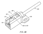
- Fig. 8B depicts the interconnection of cable end module 400 and straight coupler 310.
- Fig. 8B clearly depicts the rounded cavity region 365 sized and shaped to received the projecting rounded distal portion 360 of a module.
- Fig. 8B also shows a connector block 410 positioned to mate with a connector block in a module inserted into straight coupler 310.
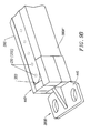
- cable end module 400 is shown as having been removed from straight coupler 310 (in Fig. 8B ).
- Slot 370 on the rounded distal end of module 400 is also shown. Note that two light units (230 or 250) are shown on end module 400, the pitch distance between these two light units preferably being identical to the pitch on a mating module
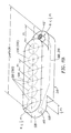
- Fig. 9A is a side perspective view of a main module, e.g., 280", and depicts slots 370 formed in each rounded distal end 360.
- An array of light detectors or emitters (230, 250) are shown.
- Detectors (or emitters) 230' (250') are intentionally shown as being somewhat staggered in their positioning. As noted earlier, some error in placement of the individual detectors/emitters and indeed in non-parallelism between spaced-apart light emitter systems and light detector systems can be tolerated.
- Fig. 9B depicts the interface between a straight module (e.g., 280) and terminating end 380B", for example as shown in perspective at the bottom portion of Fig. 3B .
- Fig. 10A is a perspective view of a bottom member 397C for a straight coupler (see 310 in Fig. 3B ), and shows the mating electrical connector blocks 410, 410'. Not shown is electrical wiring or leads connecting pins on one of the connector blocks to pins on the other block.
- Fig. 10A also shown rounded cavity regions 365 sized to retain the rounded distal end of a module whose electrical connector will mate with 410 or 410'.
- Fig. 10B depicts the bottom member 383C (380B') for an angled coupler such as 330 in Fig. 5 or in Fig. 3B . Again the rounded cavity regions 365 and projecting slots 390, and connector blocks 410, 410' used to engage and mate with an adjacent module are shown.
- Fig. 10C is a perspective view of member 397A, which comprises part of the straight coupler 310 shown in Fig. 3B . Again, the present of a rounded region and projecting rib is seen.
- Fig. 10D depicts upper member 380A" for a terminating end (see Fig. 3B ).
- FIG. 10E is a perspective view of the innermost portion 381A' of an angled coupler, e.g., 330' in Fig. 3A .
- Fig. 10F is a perspective view of the bottom portion of terminating end 380B", as shown in Fig. 3A .
- members referred to as upper or bottom may in fact be bottom and upper.
- Figs. 11A and 11B will now be described with respect to modules and light emitter systems and light detector systems in which adjacent main modules are modularly and pivotably or swivallably attachable to each other at a desired angle within a range of about ⁇ 90° (e.g., 180° overall rotation) without using couplers.
- ⁇ 90° e.g. 180° overall rotation
- couplers join adjacent modules
- a light curtain is provided whose angular displacements (if any) between adjacent main modules are fixed at the time of construction of the angled couplers.
- the embodiments of Figs. 11A and 11B are directed to such applications.
- Fig. 11A depicts a module 510 that includes an array of spaced-apart light emitters 230 or light detectors 250.
- adjacent light emitters or light detectors are spaced-apart with a pitch or granularity distance P1.
- the distal end 520, 520' of each module 510 is rounded with a radius R, and includes a preferably rotatable electrical connector 412, 412' that will engage with a mating electrical connector on an adjacent such module.
- rotatable it is meant that if adjacent modules are rotated, the connectors will maintain electrical interconnection. Note in Fig.
- the connector 412 at one surface of the rounded distal end of the module is on the underside of a ledge 530 that overhangs the flat edge of the lower surface at the module at that end.
- the electrical connector 412' is disposed on an upward facing surface of a rounded ledge 520' that extends beyond the rounded upper surface of the module at that end.
- a connector 412 facing down from one end of a similar module can interconnect with upward facing connector 412' on the module shown in Fig. 11A .
- the modules are formed with the geometry shown in Fig. 11A .
- L nP1+2R for R ⁇ 0.5 P1.
- the radius R of each distal end of the module is sized such that R ⁇ 0.5P1.
- the module underside 525 has a rounded ledge 530 that extends a distance 0.5P1, measured to the center of the distal-most light emitter or light detector.
- electrical coupler 412 is disposed on the underside region 525.
- electrical leads or wires 260 or 270 within housing 540 of module 510 are coupled from pins in connector 412 at one end 520 of module 510, to the light emitters or light detectors 250, 230 on the module, to pins in connector 412' at the other end 520' of the module.
- a light emitting system 210' or a light receiving system 220' is shown as comprising several modules 510, 510', 510" that are interconnected together and swivelled through an arbitrary angular offset. If system 210' is a light emitting system, then modules 510, 510', etc. will include an array of light emitters 230, spaced apart from each other by a pitch distance P1. If system 220' is a light detecting system, then the modules will carry light detectors 250 rather than light emitters, and the light detectors will be arrayed with a spaced-apart pitch distance P1. In Fig.
- different modules may have different lengths, e.g., L1 need not be equal to L2, and so forth.
- a system 200 providing a light curtain such as curtain 240 in Fig. 1B will include a spaced-apart (typically vertically spaced-apart) light emitting system 210' and light detecting system 220', in which systems 210' and 220' preferably comprising groupings that include modules such as module 510 shown in Fig. 11A .
- module 510 and module 510' are swivallably coupled together and offset, relative to one another, by an angle ⁇ , for example perhaps 90°.
- ⁇ for example perhaps 90°.
- distal most end portion 520 of module 510 overlaps and sits atop the distal most ledge end portion 520' of module 510'.
- swivel connectors such as 412, 412' (see Fig. 11A ) matingly engage with each other, e.g., a connector attached to a bottom-facing surface of module 510 engages a connector attached to a top-facing surface of module 520' (see Fig.
- One or both of the mating connectors may be partially recessed within the associated module. In this manner, electrical and mechanical interconnection is made between adjacent modules, while permitting the two modules thus coupled to swivel or pivot through almost any angle 0° ⁇ 180°, as dictated by the desired perimeter of the light curtain.
- Termination modules are preferably provided at the distal end of a light emitting or light detecting system.
- end module 510' in the coupled-together string of modules will provide termination for the electrical leads 260, 270 carried from module-to-module via rotatable connectors 410, 412.
- module 510" will provide coupling to electronics 70, 80.
- a technician installing a light curtain (e.g., curtain 240 in Fig. 1 B) comprising spaced-apart light emitter system 210' and light detector system 220' around machine 10, such as shown in Fig. 1B , can provide a required angle ⁇ at the job site.
- flanges or other mechanisms 520 may be used to secure the modules to a working surface (e.g., surface 55 in Fig. 1B ) or surface on a machine to be protected (e.g., machine 10 in Fig. 1B ).
- the ability to thus form a customized light curtain whose locus may include various angles (e.g., ⁇ , ⁇ 1, ⁇ 2, etc. in Fig.
- modules such as shown in Figs. 11A and 11B could be formed to mate with modules and/or couplers such as shown in Fig. 3A , for example, to enhance flexibility in implementing a desired light curtain shape.
- couplers/modules may be used to implement such portions of the light curtain.
- the present invention fulfills the shortcomings of prior art light curtains.
- light emitters in a light curtain are triggered sequentially (e.g., by electronics 70 and/or 80).
- the details of light emitter activation, or of light detector signal processing are relatively unimportant with respect to the various embodiments of the present invention.
- a light emitting system according to the present invention may be used to present a modular articulated source of visible light that is not necessarily sequenced. Systems that emit visible light with a 100% duty cycle (e.g., always on) or a sufficiently high duty cycle to reduce flicker could be used in lieu of conventional ceiling mounted track lighting units.
- a light emitter system such as shown in Fig. 11B might be attached to a ceiling in a room to provide room lighting.
Landscapes
- Physics & Mathematics (AREA)
- Life Sciences & Earth Sciences (AREA)
- General Life Sciences & Earth Sciences (AREA)
- General Physics & Mathematics (AREA)
- Geophysics (AREA)
- Length Measuring Devices By Optical Means (AREA)
- Geophysics And Detection Of Objects (AREA)
- Switches Operated By Changes In Physical Conditions (AREA)
- Light Guides In General And Applications Therefor (AREA)
- Curtains And Furnishings For Windows Or Doors (AREA)
- Non-Portable Lighting Devices Or Systems Thereof (AREA)
- Joints Allowing Movement (AREA)
- Mechanical Pencils And Projecting And Retracting Systems Therefor, And Multi-System Writing Instruments (AREA)
- Cable Accessories (AREA)
- Burglar Alarm Systems (AREA)
Abstract
Description
- This invention relates generally to protective devices such as light curtains and more particularly to providing a modular articulated light curtain whose elements may be retained at user selected angles, preferably while retaining light beam resolution through the angles.
- Light curtains are commonly used to protect hazardous areas from intruding persons or objects. For example, a particular piece of machinery may be dangerous to humans who come too close. By mounting a protective screen of so-called light curtains at the periphery of the danger zone, the presence of an intruding object or portion of a person can be detected. Detection can be used to signal an alarm, turn off the machinery, among other functions.
- Light curtains are spaced-apart light emitters and light detectors. Depending upon the application, the spaced-apart distance may range from perhaps 20 cm to perhaps 6 m or more. Absent an intruding object, the light emitting portion of the light curtain emits light that passes through empty space to be detected by the light detecting portion of the curtain. However the presence of an object will block transmission of some of the light, causing the light receiving portion to output a warning signal or command. Typically the lights are turned-on in a series sequence, one at a time.
Fig. 1A depicts a piece ofmachinery 10 to whosefront edge 20 there is mounted thelight receiving unit 30 of alight curtain 40, and at whosebase 50 there is mounted thelight emitting unit 60 oflight curtain 40, according to the prior art. As indicated inFig. 1A , the light emitting and light receiving units are coupled toelectronics - The emitted
light 90 traverses the region or zone 100 to be protected. If the protected zone is regarded as a plane defined by an array of light emitters and an array of light detectors, each array disposed in parallel straight lines, as shown inFig. 1A , standard prior artlight curtain devices 40 may be used. However when the protected region 100 involves angles and bends, it is difficult to provide a light curtain without modifying existing components. For example, it typically becomes necessary to stack portions of the light emitters on more than one plane, and to stack portions of the light detecting units on more than one plane. For example, it is desirable to maintain light beam resolution through such angles or bends, yet this design goal is not readily met in the prior art and resolution is degraded in attempting to protect curved or angular regions. - Thus there is a need for a preferably modular articulated light curtain. Preferably such light curtain should maintain light beam spacing throughout, or give the option to intentionally alter beam spacing at desired regions. Such light curtain should permit the user to shape it into desired angles, for example a zig-zag shape, and to retain the light curtain in such configuration to accommodate differently shaped regions to be protected. As noted, light beam spacing should be preserved though the desired angles. Preferably such light curtain should provide modular light emitting units and modular light detecting units, which individual modules are on a single plane, regardless of the angular configuration. As such, one pair of a light emitting module and a light receiving module will preferably be parallel to each other but can tolerate error in planarity, for example ±12°.
- The present invention provides such a light curtain.
-
EP 0 369 386 - The present invention is defined by claim 1. In a first embodiment, the present invention provides modules that are joined at a module end with a coupler. A module may be straight, curved, or angled, and will have rounded distal ends, and will include light emitters or light detectors. By contrast, couplers do not include light emitters or light detectors (generically termed herein as light units), can be straight or angled, and have an interior region sized to receive the rounded distal end of an adjacent module. Modules and couplers each include electrical connectors that can matingly engage from a module to a coupler. Within a light emitting module or within a light detecting module, it is preferred that adjacent light emitters or adjacent light detectors, respectively, are spaced-apart from each other with a desired pitch.
- As used herein, "light unit" will be understood to refer to a light emitter or to a light detector. Thus a module may generically be considered as having an array of light units spaced-apart from each other a desired pitch. If the light units are light emitters the module is a light emitting module, and if the light units are light detectors, the module will be referred to as a light detecting module. Each module also includes at least one electrical wire or trace coupled to the light emitters or to the light detectors within the module. Couplers maintain electrical continuity between adjacent modules such that electrical signals can be carried across the length of a connected series of modules and couplers. Further, couplers can maintain the desired pitch between adjacent light emitters or adjacent light detectors in adjacent modules. The two distal ends of a series of modules and couplers are terminated with appropriate terminating units. One unit provides electrical termination to the series, will typically not include any light emitters or detectors and can be regarded as a special form of coupler. The other terminating unit brings electrical leads and signals to and from the series, and may include at least one light emitter or detector, and can be regarded as a special form of module.
- By way of example, a portion of a light curtain intended to protect two adjacent straight regions having lengths L1, L2, joined at an angle of θ could be implemented as a first straight module of length L1, an angled coupler defining the desired angle θ, and a second module of length L2. If, for example, L1 were longer than a standard length module, the L1 length might be implemented using several shorter length straight modules each having length L3, joined together with straight couplers, such that the several L3 length modules added up to the desired overall length L1.
- The light curtain is defined by a plane that is itself defined by the locus of the light emitting module(s) and the light emitting coupler(s). It is understood that the light emitting modules are spaced apart but parallel to light detecting module(s), such that the locus of the light emitting modules and the locus of the light detecting module are the same. The spaced-apart distance between light emitting and light receiving modules may, but need not be, vertical in orientation and can vary from perhaps 0.25 M to 30 M or even larger. Non-planarity between a spaced-apart light emitter in a module and a corresponding light detector in a module can be tolerated within limits, for example ±12°.
- When detection of emitted light by a corresponding light detector is interrupted, for example by an object intruding in the protected region, an electronic signal carried by the wire or trace in the module/coupler will manifest this interruption. The wire/trace is coupled to conventional electronic drive and detection circuitry that can utilize the signal to identify an intrusion. Such circuitry can, for example, be used to shut down protected machinery, sound an alarm, etc.
- An alternative embodiment of the present invention provides modules that pivotably interlock with each other such that a desired angular offset between adjacent modules in the light curtain is readily achieved. As such, the modules interlock directly with each other without requiring an intervening coupler. The modules have rounded distal ends whose radius R ≤ P1/2, where P1 is the pitch of adjacent light units (e.g., light emitters or adjacent light detectors P on the module). The distal end to distal end distance L of the modules is (n+1)P1, where n is the number of light emitters or light detectors on the module. Pivoting electrical connectors at the rounded distal end of such modules mate to provide electrical continuity and mechanical stability to the resultant light emitting system or light detecting system. A light emitting system so configured may be used in lieu of conventional ceiling or wall track lighting.
- Other features and advantages of the invention will appear from the following description in which the preferred embodiments have been set forth in detail, in conjunction with the accompanying drawings.
-
-
FIG. 1A depicts a straight zone adjacent a piece of machinery protected with a conventional light curtain, according to the prior art; -
FIG. 1B depicts a non-straight zone adjacent a piece of machinery protected with an articulated modular light curtain that includes straight and curved modules, and straight and angled couplers, according to the present invention; -
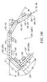
FIG. 2A is a perspective view of an exemplary articulated modular light curtain light emitter or light detector system comprising straight modules, angled couplers, a terminating unit, and a cable end module, according to the present invention; -
FIG. 2B is a shaded perspective view of the embodiment ofFig. 2A ; -
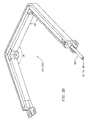
FIG. 3A is a perspective exploded view depicting straight modules, and component members of angled and straight couplers, and terminating units, according to the present invention; -
FIG. 3B is a shaded perspective view of the embodiment ofFig. 3A ; -
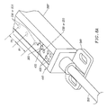
FIG. 4 is a detailed perspective view of a cable end module or terminating unit with optional light unit(s), according to the present invention; -
FIG. 5 is a detailed exploded view of an embodiment of an angled coupler implemented with upper and lower members, according to the present invention; -
FIG. 6 is a detailed perspective view of a one-piece angled coupler, according to the present invention; -
FIG. 7A is a perspective view of a portion of a light curtain depicting adjacent straight modules joined by a 90° angled coupler that preserves optical beam resolution through the angle, according to the present invention; -
FIG. 7B is a perspective view of a portion of a light curtain depicting adjacent straight modules joined by a 135° angled coupler that preserved optical beam resolution through the obtuse angle, according to the present invention; -
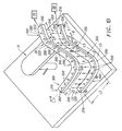
FIG. 8A is a perspective view showing the coupling between a cable end module and an adjacent main module, according to the present invention; -
FIG. 8B is a perspective view showing coupling between a straight coupler and a cable end module, according to the present invention; -
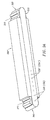
FIG. 8C is a detailed perspective view of the cable end module ofFig. 8B , according to the present invention; -
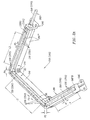
FIG. 9A is a side perspective view of a straight module, according to the present invention; -
FIG. 9B is a perspective view depicting the interface between a straight module and a terminating end, according to the present invention; -
FIG. 10A is a perspective view of a bottom portion of a straight coupler, according to the present invention; -
FIG. 10B is a perspective view of a bottom portion of an angled coupler, according to the present invention; -
FIG. 10C is a perspective view of one of the two members in a two-member upper portion of a straight coupler, according to the present invention; -
FIG. 10D is a perspective view of an upper member of a terminating end, according to the present invention; -
FIG. 10E is a perspective view of the innermost portion of an upper member of an angled coupler, according to the present invention; -
FIG. 10F is a perspective view of the bottom portion of terminating end, according to the present invention; -
FIG. 11A is a perspective view of a main straight module useable without an intervening coupler, according to a second embodiment of the present invention; -
FIG. 11B is a plan view of a portion of a light curtain implemented using the coupler ofFig. 11A to achieve user variable angular displacement, according to the present invention. -
Fig. 1B is a perspective view of a generic light curtain system 200, according to the present invention, used to protectmachinery 10 or other region requiring protection. System 200 may be described as comprising modules (straight, curved, or angled) that include light units (e.g., light emitters or light detectors) spaced-apart from other light units with a desired pitch or granularity (e.g., so many light units per unit length). System 200 further include couplers (straight or angled) that join adjacent modules, and also includes terminating units disposed at the end of a series of modules and couplers. - Affixed adjacent the
front region 20 ofmachinery 10 is a light detectingsystem 210, and disposed nearfront region 50 of a work surface 55 (or equivalent) there is a spaced-apart light emittingsystem 220 mounted in a preferably parallel or near parallel orientation.Light emitting system 220 includes a plurality oflight emitters 230 spaced-apart from each other with a desired pitch or granularity, e.g., so many light emitters per unit length. As will be described, thelight emitters 230 are disposed in modules and, if required, in a cable end termination module. -
Emitters 230 emit a curtain of light 240 that is detected (in the absence of an intervening object) bylight detectors 250 in modules and, if required, in a cable end termination module, indetector system 210. The spaced-apart pitch ofadjacent detectors 250 preferably is identical to the pitch oflight emitters 230. When implemented with components available at the present time, pitch distances (P1) may be on the order of perhaps 3 mm to 50 mm or larger. The plane of the locus defined bylight emitter system 220 will be parallel to the plane defined bylight detector system 210, although between a given light emitter and its corresponding light detector (e.g., the detector that will receive light from that emitter), non-planarity is tolerated such that angle Φ may be about ±12°, e.g., a relative mis-match in planarity with about ±12° is acceptable. The spaced-apart distance between the light emittingsystem 220 and thelight receiving system 210 may be about 0.25 M to about 30 M, depending upon the application. As in the embodiment ofFig. 1A ,electronics electrical lead systems light curtain 240, signal(s) carried by these leads toelectronics shutdown machinery 10, to sound an alarm, etc. - In comparing
Figs. 1B and1A , it is seen fromFig. 1B that the present invention provides a light curtain that can includestraight regions 280 that may be joined at an angle θ, and can includecurved regions 290. As noted, the pitch of adjacentlight emitter units 230 or of adjacentlight detector units 250 preferably is held constant through the straight, angular, and curved module regions that define the shape or locus of the light curtain. If desired, however, different regions could have different pitches (e.g., correspondingly different pitches for the same light emitter region and light detector region) by using modules with correspondingly differently pitched light units. - As will be described, system 200 is modular in that a desired light curtain path or locus can be implemented by combining modules (straight, angled, or curved) together with couplers (straight or angled). In
Fig. 1B , as will be described,straight region 300 may be implemented by linking adjacent straight modules with a straight coupler if length L2 is not available using a standard length straight module.Curved region 320 may be implemented using curved modules, andangled region 330 may be implemented using angled modules or by combining adjacent straight modules with an intervening angled coupler that may have been manufactured with the desired fixed angular offset θ. - It will be appreciated that the terms light emitter and light detector may be interchangeable. Thus, whereas
Fig. 1B depicts the overall light emitter system as mounted to awork surface 55 and the overall light detector system as mounted tomachinery 10, one could instead replace the light emitter system with the light detector system and vice versa. Further plane of the light curtain inFig. 1B could be other than vertical, for example by orienting the light emitting and light detecting systems in other than a relative vertical offset position. -
Fig. 2A will be described as though the modular articulated system shown is the light emittingsystem 220 of a light curtain according to the present invention. However, as noted, the position oflight emitters 230 may in fact be exchanged withlight detectors 250 such thatFig. 2A is applicable to light detectingsystem 210. - In
Fig. 2A , three main straight modules 280 (having length L1), 280' (having length L2) and 280" (having length L3) are shown, where L1 may differ in length from L2 or/or L3. As shown, each module includes light emitters 230 (orlight detectors 250 ifFig. 2A is understood to refer to light detector system 210). Inmodule 280, the spaced-apart distance of pitch ofadjacent emitters 230 is denoted P1, in module 280' the pitch is P3, and inmodule 280" the pitch is P5. Typically pitch spacing of the light emitters (or light detectors) within a main module is such as to provide object resolution according to applicable standard, for example, presently at least 14 mm object resolution. It is understood with respect toFig. 2A , that each straight module shown will include light transmitters/emitters or light receivers, depending upon whether the module is in the light emitting or light detection portion of the overall light curtain, spaced-apart with a desired pitch. Commonlylight emitters 230 will be LEDs or laser emitting diodes, but other devices may instead be used. The emitted spectra for the curtain may be visible or invisible to the human eye. Shown in phantom inFig. 2A is the at least one electrical lead or trace 250 (270) within the main modules coupled to the various light emitter units (light detector units) and toelectronics - As noted with respect to
Fig. 1B , the orientation between light emittingsystem 220 and light detectingsystem 210 is such that in the absence of an intervening object, at least some light emitted bysystem 220 will be detected by light detectingsystem 210. In addition to tolerating some angular offset in planarity, offset in the position of individuallight emitters 230 orlight detectors 250 can also be tolerated. For example, whileFig. 2A depicts the light emitters (detectors) as being in an array through which a straight line may be drawn within a straight module, the position of a given light emitter or detector could be changed by about 5 mm in any direction (including up or down) without destroying utility of the invention. - In
Fig. 2A adjacent straight main modules are joined or interconnected with a coupler. Thusmodules 280 and 280' are joined by anangled coupler 330, here shown defining an obtuse angle θ1.Straight modules 280' and 280" are also shown joined by anangled coupler 330, whose angle θ2 is shown as 90°. If necessary, interconnection between the straight modules could be made using astraight coupler 280"'. The various angled and straight couplers provide mechanical and electrical continuity through the light emitting and light detecting systems. Each curved coupler and each angular coupler includes light emitter(s) 230 or light detector(s) 250. The spaced-apart pitch P2, P4 associated with these couplers is preferably identical to that associated with the straight modules, e.g., P1 = P2 = P3 = P4 = P5. The result is that even though the light curtain is bent or curved, e.g., through an angle θ1 or θ2, the spaced-apart pitch of the light emitters or light detectors can remain constant. As a result, optical beam spacing (e.g., resolution) between adjacent modules can be preserved from one module, through a desired coupling angle, and into the adjacent module. As will be described, any or all ofcouplers - Brackets such as 340 may be used to mechanically connect light emitting or detecting
system work surface 55, and/or tomachinery 10.Fig. 2A depicts aprotective sheath 350 around wires or leads 250, 270. As noted, such leads are coupled toelectronics 70 and/or 80 that provide electrical power and signals to the present invention, and which can process signals output by the present invention. Such signals, when processed, can be used to identify intrusion of an object into the light curtain surrounding the region to be protected.Fig. 2B is a shaded perspective view of what is shown inFig. 2A . - The exploded view shown in
Fig. 3A shows preferred implementation of straightmain modules 280, 280' 280",straight coupler 310, and fixed angle couplers such as 330. Also shown are terminatingunit 340, and cableend module unit 400, which optionally can include one or morelight units rounded members 360 whose projection sides define at least oneslot 370.Angled coupler 330 may thus be formed with anupper member 380A that comprises inner andouter components lower member 383C (380B), which members including a projection or the like 390 that mates with theslot 70 defined in therounded projection member 360 of the distal end of an adjoining module, e.g.,module 380 or 380' inFig. 3A . Further, arounded cavity region 365 is preferably defined within the various coupler members to receive the rounded distal end of a module retained within that coupler. - If a straight line portion of a light curtain is required to be longer than the standard length of a main module, several main straight modules may be coupled together using straight couplers such as
coupler 310. As shown inFig. 3A , a straight line coupler may comprise upper and lower members, in which the upper member comprises left andright components lower member 397C make up the coupler.Components screws 397 or the like. - It may be desired to provide some standard modules with greater or less granularity (or pitch) of light emitter or detector spacing than other standard main modules. Perhaps some regions of a protected zone will require higher optical resolution than others, for example to detect intrusion of a human finger as opposed to detecting intrusion of a human torso. For example in
Fig. 2A ,main module 280" may require a smaller pitch P5 thanmodule 280, which has a pitch P1. This feature is provided by fabricating some standard modules with greater or lesser granularity. If desired, modules having different pitched light units could be color coded to indicate the pitch resolution. For example, standard modules with a high density of emitters or detectors (for example 14 mm pitch, measured center-to-center from light emitter or light detector mounting) may have one color, whereas lower density modules may have a different color. (It is understood that "color" refers to the module body, and not to the light emitted by light emitters within the module.) - Referring to
Fig. 3A (andFig. 7A ), mainstraight modules 380, 380' are joined by an angled coupler 320' that defines approximately a 90° bend. Upper andlower members 380A' and 380B' are placed, respectively, above and below distal ends 360', 360" of main modules 280' and 280'. The mechanical interlocking formed by mating vertically projecting ribs (e.g., 390) and slots (e.g., 370) enablemembers 380A', 380B' to securemodules 280', 280" at an offset angle θ that is here defined by the geometry of coupler 320'. Of course other configurations for rotatably connecting adjoining modules could be provided, preferably while maintaining a constant optical resolution across any intervening joining angle. - As shown in
Fig. 3A , screws or other joiningdevices 397 then secure upper andlower members 380A', 380B' together, thereby retainingadjacent modules 280', 280" at the desired bend angle.Fig. 3A does not depict the light units (e.g,., light emitters or light detectors) arrayed in the modules but as noted preferably the spaced-apart pitch of the emitters or detectors remains constant through the bend θ. Note thatFig. 3A depicts astraight coupler 395 that may be used to join adjacent main modules, for example to provide a great overall length, or in the embodiment ofFig. 3A , to provide a coupling to acable end module 400. (Module 400 will be described in further detail in conjunction withFig. 4 .) - At the lower right portion of
Fig. 3A , thecoupler comprising members 380A", 380B" may be defined as an end or terminating coupler, e.g., no other coupler or main module is connected through this coupler. As such, proper termination, as necessary, of relevant electrical leads at a distal end of the light curtain may be made within this coupler. (The other distal end of the light curtain will be terminated with thecable end module 400.) The terminating end coupler essentially completes and closes the electrical interconnection paths within the light emitting or light detecting system portion of the light curtain array. In the preferred embodiment, a terminating end coupler will not include any light units. - Although
Fig. 3A depicts couplers and main module distal ends that interlock using ribs and slots, those skilled in the mechanical arts will appreciate that other mechanism could instead be used to mate together adjacent main modules, or to mate modules to couplers, at a desired bend angle. However they are joined, adjacent modules will preserve the optical beam resolution through any bend angle, according to the present invention. As will be described further with respect toFigs. 4-6 , continuity of electrical interconnections between main modules is also preserved across intermediate couplers. -
Fig. 3B is a shaded perspective view of the embodiment of what is shown inFig. 3A . It will be appreciated fromFigs. 3A and3B that the present invention provides a mechanism by which beam optical resolution may be preserved through bends and angles in a light curtain system. The resultant light curtain may be extended in a straight line, for example by inter-coupling main modules with a straight coupler, or may be bent or curved, for example, by inter-coupling main modules with curved or angled couplers. In a practical system, it is understood that ifFig. 3B depicts alight emitting system 220, then there will be a similarly configured (e.g., similar locus) light detectingsystem 230 spaced apart (perhaps vertically) to preserve parallelism within an acceptable error. - Referring to
Fig. 4 , a preferred embodiment of acable end module 400 is shown.Distal end 430 ofmodule 400 is rounded and preferably has the same curvature or radius R as the distal ends of the main modules have. This curvature is sized to fit within the curved cavity regions internal to the various couplers. Note thatmodule 400 may include one (or more)light units end module 400 and the distal-most portion ofrounded region 430 is such as to preserve granularity or pitch between the adjoining module andmodule 400.Cable end module 400 brings electrical signals and power into the light emitting or light detecting system, and is also coupled signals from the light emitting or light detecting system toelectronics 70 and/or 80. For the light emitting system of a light curtain,electronics 70 and/or 80 will include drive signals for the light emitters. For the light detecting system,electronics 70 and/or 80 will signal process detection signals output by the light detectors. The design and implementation ofelectronics 70 and/or 80, and of alarm systems and machinery power interrupting circuits, is well known to those skilled in the art of circuit and signal processor design. Accordingly further details ofelectronics 70/80 are not presented here. - Preferably a user viewable surface of at least one module in the light curtain, e.g.,
cable end module 400 inFig. 4 , includes at least oneindicator 420, for example LED(s). Activation of one or more ofLEDs 420 can provide useful information as to operational status of the overall light curtain system. For example, indicator(s) 420 can signal that operating power is present to the system, and that the transmitting or detecting unit to which the indicators are attached appears to be functioning normally. As further shown inFig. 4 , preferably some of the couplers will include a mountingflange 340 or other feature enabling the modular assemblies to be screwed, bolted, or otherwise attached to the regions adjacent the protected zone. -
Fig. 5 provides further detail as to a preferred embodiment of anangled coupler 330, comprising upper members (383A, 383B) and lower member (383C). Of course it is understood that members denoted upper and lower could instead be lower and upper. At the time of manufacture, the angled coupler shown inFig. 5 will be formed with a desired fixed angle θ, for example 60°. - Note that one of the members, here
member 383C (or 380B'), includes electrical connection blocks 410. The roundeddistal end 360 of a main module (e.g., 280') includes a mating connector 410' (e.g., male ifblock 410 is female, or vice versa). When the light detecting or light emitting system is assembled, the roundeddistal end 360 of a main module is inserted into therounded region 365 in a coupler. In the embodiment ofFig. 5 , the main module is then pushed downward such that there is a mating not only between slots and projecting ribs, but also betweenconnectors 410, 410'. Wiring (not shown) within 380B' interconnects pins between the twoconnector blocks 410, such that when two main module are mechanically and electrically connected via the coupler, there is electrical interconnection from main module to main module via the connector blocks. Screws or other devices then join togethermembers 380A', 380B' around the distal end of two main module members. If desired,members 380A', 380B' could be fabricated to simply snap together, obviating the need for screws or the like. - As shown by the alternative embodiment of
Fig. 6 , an angled coupler 330' may be fabricated as a single unit (rather than as a combination of members). Further, as shown inFig. 6 , electrical interconnection between mating modules and/or their electrical connectors need not be made by pushing a main module downward to mate with a coupler. If desired, the electrical interconnections via connector blocks 410, 410' may be made by inserting the roundeddistal end 360 of a main module into therounded region 365 within a coupler such as 330' inFig. 6 . The specific mechanics for the electrical interconnection is not critical providing that the electrical connectors permit various elements of the light curtain to be modularly interconnected. - Turning now to
Fig. 7A ,straight modules 280', 280" are shown joined by aangled module 330, that provides a fixed θ = 90° angle to the overall light emitting or light detecting system 210 (or 220). In this example, a fixed pitch P1 is shown preserved across coupler 320'. Stated differently, the distance between adjacent light emitters 230 (or light detectors 250) is the same, whether measured along the length of a main module, or across the coupler. If the distance between adjacent light emitters/detectors is P1, then the radius R of thecurved region 360 of each distal portion of a main module is P1/2, e.g., 2R ≤ P1. If desired one could instead reduce R such that a different pitch is provided across a coupler. -
FIG. 7B is a perspective view of a portion of a light curtain depicting preservation of optical beam resolution through an obtuse angle bend θ1. InFig. 7B , straightmain modules 280, 280' are joined by a fixed obtuse angled coupler 320 (or 330). Magnitude of the angle is determined by the geometry of the curved coupler and will have been manufactured to accommodate the machinery or region to be protected with a light curtain. If the spaced-apart distance P1 between adjacent light emitters or light detectors 230 (250) is P1, then the radius R defining the curveddistal portions 360 of the main modules is again made less than or equal to P1/2. In this manner a constant pitch or optical beam resolution is maintained across the obtuse bend. - It will be appreciated from the above description including that of
Figs. 7A and 7BA that adjacent main modules are rotatable along an optical radius (e.g., normal to a distal-most light emitter or light detector) such that the spaced-apart pitch between adjacent light emitters or light detectors can be preserved. As noted, this feature enables constant optical resolution to be maintained along the beam curtain. This feature is achieved if the radius R of the rounded distal end of a main module (measured from the center of a distal-most first or last light emitter or light detector) is ≤ P1/2, where P1 is the pitch between adjacent light emitters or light detectors. -
Fig. 8A shows further details of the interface betweencable end module 400 and an adjacent main module, here 280". In the end module shown, a light unit 230 (or 250) is disposed a uniform pitch distance P1 away from thenearest light unit 230" (or 250") in the connected main module. -
Fig. 8B depicts the interconnection ofcable end module 400 andstraight coupler 310.Fig. 8B clearly depicts therounded cavity region 365 sized and shaped to received the projecting roundeddistal portion 360 of a module.Fig. 8B also shows aconnector block 410 positioned to mate with a connector block in a module inserted intostraight coupler 310. InFIG. 8C ,cable end module 400 is shown as having been removed from straight coupler 310 (inFig. 8B ). Slot 370 on the rounded distal end ofmodule 400 is also shown. Note that two light units (230 or 250) are shown onend module 400, the pitch distance between these two light units preferably being identical to the pitch on a mating module -
Fig. 9A is a side perspective view of a main module, e.g., 280", and depictsslots 370 formed in each roundeddistal end 360. An array of light detectors or emitters (230, 250) are shown. Detectors (or emitters) 230' (250') are intentionally shown as being somewhat staggered in their positioning. As noted earlier, some error in placement of the individual detectors/emitters and indeed in non-parallelism between spaced-apart light emitter systems and light detector systems can be tolerated. -
Fig. 9B depicts the interface between a straight module (e.g., 280) and terminatingend 380B", for example as shown in perspective at the bottom portion ofFig. 3B .Fig. 10A is a perspective view of abottom member 397C for a straight coupler (see 310 inFig. 3B ), and shows the mating electrical connector blocks 410, 410'. Not shown is electrical wiring or leads connecting pins on one of the connector blocks to pins on the other block.Fig. 10A also shownrounded cavity regions 365 sized to retain the rounded distal end of a module whose electrical connector will mate with 410 or 410'. -
Fig. 10B depicts thebottom member 383C (380B') for an angled coupler such as 330 inFig. 5 or inFig. 3B . Again therounded cavity regions 365 and projectingslots 390, and connector blocks 410, 410' used to engage and mate with an adjacent module are shown.Fig. 10C is a perspective view ofmember 397A, which comprises part of thestraight coupler 310 shown inFig. 3B . Again, the present of a rounded region and projecting rib is seen.Fig. 10D depictsupper member 380A" for a terminating end (seeFig. 3B ).Fig. 10E is a perspective view of theinnermost portion 381A' of an angled coupler, e.g., 330' inFig. 3A .Fig. 10F is a perspective view of the bottom portion of terminatingend 380B", as shown inFig. 3A . Again, it is understood that members referred to as upper or bottom may in fact be bottom and upper. -
Figs. 11A and11B will now be described with respect to modules and light emitter systems and light detector systems in which adjacent main modules are modularly and pivotably or swivallably attachable to each other at a desired angle within a range of about ± 90° (e.g., 180° overall rotation) without using couplers. This is in contrast to the various embodiments thus far described in which couplers join adjacent modules, and in which a light curtain is provided whose angular displacements (if any) between adjacent main modules are fixed at the time of construction of the angled couplers. However in some applications it may be necessary or desirable to provide an angled portion in a light curtain that is not readily available from angled couplers. The embodiments ofFigs. 11A and11B are directed to such applications. -
Fig. 11A depicts amodule 510 that includes an array of spaced-apartlight emitters 230 orlight detectors 250. In the embodiment shown, adjacent light emitters or light detectors are spaced-apart with a pitch or granularity distance P1. Thedistal end module 510 is rounded with a radius R, and includes a preferably rotatableelectrical connector 412, 412' that will engage with a mating electrical connector on an adjacent such module. By rotatable it is meant that if adjacent modules are rotated, the connectors will maintain electrical interconnection. Note inFig. 11A that theconnector 412 at one surface of the rounded distal end of the module is on the underside of aledge 530 that overhangs the flat edge of the lower surface at the module at that end. However on the other rounded distal end of the module, the electrical connector 412' is disposed on an upward facing surface of arounded ledge 520' that extends beyond the rounded upper surface of the module at that end. As will be described, aconnector 412 facing down from one end of a similar module can interconnect with upward facing connector 412' on the module shown inFig. 11A . - The modules are formed with the geometry shown in
Fig. 11A . Thus, if there are a number n light emitters or light detectors along the length of the module, spaced-apart a distance P1, then the overall length L of the module is given by L = nP1+2R for R ≤ 0.5 P1. The radius R of each distal end of the module is sized such that R ≤ 0.5P1. At onedistal end 520, the module underside 525 has a roundedledge 530 that extends a distance 0.5P1, measured to the center of the distal-most light emitter or light detector. In the embodiment ofFig. 11A ,electrical coupler 412 is disposed on the underside region 525. In a manner known to those skilled in the art, electrical leads orwires housing 540 ofmodule 510 are coupled from pins inconnector 412 at oneend 520 ofmodule 510, to the light emitters orlight detectors other end 520' of the module. - Turning now to
Fig. 11B , a light emitting system 210' or a light receiving system 220' is shown as comprisingseveral modules modules 510, 510', etc. will include an array oflight emitters 230, spaced apart from each other by a pitch distance P1. If system 220' is a light detecting system, then the modules will carrylight detectors 250 rather than light emitters, and the light detectors will be arrayed with a spaced-apart pitch distance P1. InFig. 11B , a light emitter system or light detector system is shown comprising six (n = 6) modules, such as shown inFig. 11A . As indicated inFig. 11B , different modules may have different lengths, e.g., L1 need not be equal to L2, and so forth. It is understood, of course, that a system 200 providing a light curtain such ascurtain 240 inFig. 1B will include a spaced-apart (typically vertically spaced-apart) light emitting system 210' and light detecting system 220', in which systems 210' and 220' preferably comprising groupings that include modules such asmodule 510 shown inFig. 11A . - The module geometry noted in
Fig. 11A is such that pitch distance P1 is maintained between adjacent modules. Thus inFig. 11B ,module 510 and module 510' are swivallably coupled together and offset, relative to one another, by an angle θ, for example perhaps 90°. In the plan view shown, distalmost end portion 520 ofmodule 510 overlaps and sits atop the distal mostledge end portion 520' of module 510'. It is understood that swivel connectors such as 412, 412' (seeFig. 11A ) matingly engage with each other, e.g., a connector attached to a bottom-facing surface ofmodule 510 engages a connector attached to a top-facing surface ofmodule 520' (seeFig. 11B ). One or both of the mating connectors may be partially recessed within the associated module. In this manner, electrical and mechanical interconnection is made between adjacent modules, while permitting the two modules thus coupled to swivel or pivot through almost anyangle 0° ≤θ≤180°, as dictated by the desired perimeter of the light curtain. - Termination modules are preferably provided at the distal end of a light emitting or light detecting system. Thus end module 510' in the coupled-together string of modules will provide termination for the
electrical leads rotatable connectors module 510" will provide coupling toelectronics - Thus a technician installing a light curtain (e.g.,
curtain 240 inFig. 1 B) comprising spaced-apart light emitter system 210' and light detector system 220' aroundmachine 10, such as shown inFig. 1B , can provide a required angle θ at the job site. Once the angle is attained, flanges orother mechanisms 520 may be used to secure the modules to a working surface (e.g.,surface 55 inFig. 1B ) or surface on a machine to be protected (e.g.,machine 10 inFig. 1B ). The ability to thus form a customized light curtain whose locus may include various angles (e.g., θ, θ1, θ2, etc. inFig. 11B ) shortens installation time, and can greatly reduce installation cost, since the light curtain is modular and can be implemented with standard interlocking components. If desired modules such as shown inFigs. 11A and11B could be formed to mate with modules and/or couplers such as shown inFig. 3A , for example, to enhance flexibility in implementing a desired light curtain shape. Thus if it is known that certain angles in the desired light curtain will be fixed, fixed couplers/modules may be used to implement such portions of the light curtain. - In summary, however implemented, e.g., with fixed angled or curved couplers, with main modules, or with pivotable modules, electrical and mechanical interconnections are secured made in a fashion that preserves pitch of the light emitters or light detectors, across curved, angled, or straight regions of the light curtain. Further, different pitch granularities (or optical resolution) may be provided, if desired, for different regions of the light curtain by coupling modules whose light emitters or light detectors have a different pitch than pitch in other regions. Light curtains of varying loci may be implemented using modular components, e.g., modules and/or .couplers, that snap or otherwise interlock together.
- It is thus seen that the present invention fulfills the shortcomings of prior art light curtains. In a typical industrial application, light emitters in a light curtain are triggered sequentially (e.g., by
electronics 70 and/or 80). However the details of light emitter activation, or of light detector signal processing are relatively unimportant with respect to the various embodiments of the present invention. For example, in a consumer application, a light emitting system according to the present invention may be used to present a modular articulated source of visible light that is not necessarily sequenced. Systems that emit visible light with a 100% duty cycle (e.g., always on) or a sufficiently high duty cycle to reduce flicker could be used in lieu of conventional ceiling mounted track lighting units. Thus, a light emitter system such as shown inFig. 11B might be attached to a ceiling in a room to provide room lighting.
Claims (12)
- A light curtain (200) coupleable to electronics (70, 80) providing operating power and drive signals and providing analysis of signals output by the light curtain, the light curtain (200) comprising:a light emitting assembly (220) and a corresponding light detecting assembly (210);
characterized by:said light emitting assembly (220) comprising interconnectable first and second light emitter modules (280, 280', 510, 510') having two rounded distal ends (360, 360', 520, 520') configured to mate electrically and mechanically with each other or with a coupler and having a plurality a light emitters (230) spaced apart at a pitch P1, each rounded distal end having a curved radius R that is less than or equal to 1/2 of the pitch P1 to maintain the pitch P1 of light emitters (230) across interconnected light emitter modules; andsaid light detecting assembly (210) comprising interconnectable first and second light detector modules (280, 280', 510, 510') having two rounded distal ends (360, 360', 520, 520') configured to mate electrically and mechanically with each other or with a coupler and having a plurality a light detectors (250) spaced apart at the pitch P1, each rounded distal end having a curved radius R that is less than or equal to 1/2 of the pitch P1 to maintain the pitch P1 of light detectors across interconnected light detector modules. - The light curtain (200) of claim 1, wherein the rounded distal ends (360, 360') of the light emitter and light detector modules (280, 280) are configured to mate with couplers (320, 330) and each comprises a rounded projection member having a curved radius R, and further comprising a first interconnecting coupler (320, 330) for interconnecting the first and second light emitting modules (280, 280') and a second interconnecting coupler (320, 330) for interconnecting the first and second light detecting modules (280, 280'), each said interconnecting coupler having rounded cavity regions (365) for receiving the respective rounded projection members of the first and second light emitting or light detecting modules (280, 280').
- The light curtain (200) of claim 2, wherein each rounded distal end (360, 360') of each light emitting and light detecting module (280, 280') includes an electrical connector, and wherein each interconnecting coupler (320, 330) includes corresponding electrical connectors (410, 410') for electrically interconnecting the first and second light emitting or detecting modules (280, 280') through the interconnecting coupler (320, 330).
- The light curtain (200) of claim 2, further comprising at least one terminating coupler or unit (340) for mounting on a rounded distal end (360) of a last light emitting or last light detecting module (280, 280') in the light emitting assembly (220) or light detecting assembly (210), and configured to provide electrical termination therefore.
- The light curtain (200) of claim 2, further comprising a first type of terminating coupler or unit (400) configured for mounting on a rounded distal end (360) of a first light emitting or first light detecting module (280, 280') in the light emitting assembly (220) or light detecting assembly (210), and configured to provide interfacing to said electronics (70, 80) providing operating power and drive signals and providing analysis of signals output by the light curtain (200).
- The light curtain (200) of claim 2, wherein said first light emitting and light detecting modules (280, 280') are selected from a group consisting of (a) straight light emitting and light detecting modules, (b) curved light emitting and light detecting modules, and (c) angled light emitting and light detecting modules.
- The light curtain (200) of claim 6, wherein the first and second couplers (320, 330) are selected from a group consisting of (a) straight couplers, (b) curved couplers, and (c) angled couplers.
- The light curtain (200) of claim 1, wherein said light emitting assembly (220) includes a number of interconnected light emitting modules, including said first and second light emitting modules (280, 280'), and said light detecting assembly (210) includes a corresponding number of interconnected light detecting modules, including said first and second light detecting modules (280, 280').
- The light curtain (200) of claim 8, wherein the number of interconnected light emitting modules comprises any desired mix of straight, curved, or angled light emitting modules, and wherein the corresponding number of light detecting modules includes a corresponding mix of straight, curved, or angled light detecting modules.
- The light curtain (200) of claim 1, wherein each module (510) in the light emitting assembly or light detecting assembly (220, 210) includes a plurality equal to a number n of light emitters (230) or detectors (250) disposed on a first surface of the module (510) according to the pitch P1, and is configured to mate to a like module (510') based on a first one of the rounded distal ends (520) of each module (510) being configured as a curved ledge with a first electrical connector (412) on its underside and a second one of the rounded distal ends (520') of each module (510) being configured as a curved shelf with a second electrical connector (412') on its topside, said first and second electrical connectors (412, 412') being electrically interconnected with the light emitters (230) or light detectors (250) of the module (510), wherein two modules (510, 510') interconnect by mating the first electrical connector (412) on the underside of the curved ledge of one module (510) with the second electrical connector (412') on the topside of the curved shelf of another module (510').
- The light curtain (200) of claim 10, wherein the first and second electrical connectors (412, 412') are cylindrical and are rotatable, thereby allowing interconnected first and second modules (510, 510') to be interconnected at a desired angle.
- The light curtain (200) of claim 1, further comprising a first type of terminating units or modules (340) for respectively terminating the light emitting and light detecting assemblies (220, 210), and a second type of terminating units or modules (400) for respectively connecting the light emitting and light detecting assemblies (220, 210) to said electronics (70, 80) providing operating power and drive signals and providing analysis of signals output by the light curtain (200).
Applications Claiming Priority (3)
| Application Number | Priority Date | Filing Date | Title |
|---|---|---|---|
| US12399499P | 1999-03-11 | 1999-03-11 | |
| US123994P | 1999-03-11 | ||
| PCT/US2000/006357 WO2000054077A1 (en) | 1999-03-11 | 2000-03-10 | Modular articulated light curtain |
Publications (3)
| Publication Number | Publication Date |
|---|---|
| EP1161694A1 EP1161694A1 (en) | 2001-12-12 |
| EP1161694A4 EP1161694A4 (en) | 2003-01-02 |
| EP1161694B1 true EP1161694B1 (en) | 2008-12-10 |
Family
ID=22412147
Family Applications (1)
| Application Number | Title | Priority Date | Filing Date |
|---|---|---|---|
| EP00912213A Expired - Lifetime EP1161694B1 (en) | 1999-03-11 | 2000-03-10 | Modular articulated light curtain |
Country Status (8)
| Country | Link |
|---|---|
| US (2) | US6297498B1 (en) |
| EP (1) | EP1161694B1 (en) |
| JP (1) | JP2002539603A (en) |
| AT (1) | ATE417290T1 (en) |
| AU (1) | AU3397500A (en) |
| DE (1) | DE60041041D1 (en) |
| ES (1) | ES2316355T3 (en) |
| WO (1) | WO2000054077A1 (en) |
Families Citing this family (31)
| Publication number | Priority date | Publication date | Assignee | Title |
|---|---|---|---|---|
| GB2364773A (en) * | 2000-02-10 | 2002-02-06 | Rwl Consultants Ltd | Improvements In Or Relating To A Light Curtain |
| US6635862B2 (en) | 2000-03-10 | 2003-10-21 | Scientific Technologies Incorporated | Mixed architecture light curtain system |
| JP3788502B2 (en) * | 2000-08-11 | 2006-06-21 | オムロン株式会社 | Light curtain creation device |
| JP4634658B2 (en) * | 2001-06-29 | 2011-02-16 | 株式会社キーエンス | Multi-optical axis photoelectric sensor and light projector and light receiver included therein |
| JP4208535B2 (en) | 2001-12-12 | 2009-01-14 | 株式会社キーエンス | Multi-optical axis photoelectric sensor and its fixture |
| JP3927503B2 (en) * | 2003-01-20 | 2007-06-13 | 株式会社キーエンス | Multi-axis photoelectric sensor |
| JP4485757B2 (en) * | 2003-05-29 | 2010-06-23 | 株式会社キーエンス | Multi-optical axis photoelectric safety device |
| USD500688S1 (en) | 2003-09-30 | 2005-01-11 | Rockwell Automation Technologies, Inc. | Housing for a sensor assembly |
| DE102004012794A1 (en) * | 2004-03-16 | 2005-11-17 | Sick Ag | light Curtain |
| JP2005300399A (en) * | 2004-04-14 | 2005-10-27 | Keyence Corp | Multioptical axses photoelectronic sensor |
| US7343062B1 (en) | 2006-01-17 | 2008-03-11 | Rockwell Automation Technologies, Inc. | Safety light curtain with MEMS |
| DE102006003954A1 (en) * | 2006-01-26 | 2007-08-02 | Sick Ag | light Curtain |
| US7540627B2 (en) * | 2006-05-08 | 2009-06-02 | Innovative Lighting, Inc. | Channel light system with pivotable connector |
| FR2903783B1 (en) * | 2006-07-12 | 2008-10-24 | Senstronic Sa Sa | OPTICAL SENSOR DEVICE WITH VARIABLE GEOMETRY. |
| DE102006059547B4 (en) * | 2006-12-16 | 2009-05-07 | Leuze Lumiflex Gmbh + Co. Kg | Light barrier arrangement |
| DE102007003026A1 (en) * | 2007-01-20 | 2008-07-31 | Sick Ag | Optoelectronic sensor and method for object detection in a surveillance area |
| US8336434B2 (en) * | 2007-10-22 | 2012-12-25 | Formax, Inc. | Food article end detection system for a food article slicing machine |
| JP5103207B2 (en) * | 2008-01-31 | 2012-12-19 | パナソニック デバイスSunx株式会社 | Multi-optical axis photoelectric sensor, its mounting structure and its mounting member |
| US7810697B2 (en) * | 2008-08-22 | 2010-10-12 | Honda Motor Co., Ltd. | Turntable welding system with light curtain protection |
| DE102009017466A1 (en) * | 2009-04-03 | 2010-10-07 | Balluff Gmbh | Photointerrupter |
| DE102010008895B4 (en) * | 2010-02-23 | 2022-08-11 | Leuze Electronic Gmbh & Co. Kg | light curtain |
| DE102010009590A1 (en) * | 2010-02-26 | 2011-09-01 | Rheinisch-Westfälische Technische Hochschule Aachen | Sensor system and method for monitoring a room |
| CA2798594C (en) | 2010-06-09 | 2016-04-05 | Baanto International Ltd. | Modular position sensing systems and methods |
| DE202011000608U1 (en) * | 2011-03-17 | 2012-06-18 | Sick Ag | Mounting profile for a light curtain housing and light grid |
| DE102013106185A1 (en) * | 2013-06-13 | 2014-12-18 | Pilz Auslandsbeteiligungen Gmbh | Light grid component |
| DE102015016312A1 (en) * | 2014-12-16 | 2016-07-14 | Datalogic Ip Tech S.R.L. | Optical unit for an optoelectronic system |
| DE102018117372B4 (en) * | 2018-07-18 | 2020-04-02 | Sick Ag | Sensor system and distance sensor module |
| FR3120976A1 (en) * | 2021-03-16 | 2022-09-23 | Orange | Method for detecting the absence of a material element in a geographical area, associated system |
| CN118043704A (en) | 2021-08-30 | 2024-05-14 | 邦纳工程公司 | Field installable light curtain side status module |
| US20250270069A1 (en) * | 2024-02-22 | 2025-08-28 | Otis Elevator Company | Orthogonally aligned safety net for elevator system |
| CN119556596B (en) * | 2024-11-21 | 2025-07-29 | 湖北弘仪智能装备有限责任公司 | Intelligent loading and unloading truck interlocking control method, system, equipment and medium for hazardous chemicals |
Family Cites Families (11)
| Publication number | Priority date | Publication date | Assignee | Title |
|---|---|---|---|---|
| US3805061A (en) * | 1973-04-23 | 1974-04-16 | Tyco Laboratories Inc | Object detecting apparatus |
| US4249074A (en) | 1978-06-06 | 1981-02-03 | Xenex Corporation | Intrusion detector for press brake |
| JPS55122598U (en) * | 1979-02-23 | 1980-08-30 | ||
| JPH0337062Y2 (en) | 1985-05-17 | 1991-08-06 | ||
| US4958068A (en) * | 1988-11-01 | 1990-09-18 | Transitions Research Corporation | Dual bumper-light curtain obstacle detection sensor |
| JPH0690900B2 (en) | 1988-11-14 | 1994-11-14 | 株式会社キーエンス | Multi-axis photoelectric switch |
| JPH0625870Y2 (en) * | 1989-08-01 | 1994-07-06 | 株式会社キーエンス | Photoelectric switch and its unit |
| US5198661A (en) | 1992-02-28 | 1993-03-30 | Scientific Technologies Incorporated | Segmented light curtain system and method |
| US5302942A (en) * | 1992-11-19 | 1994-04-12 | Scientific Technologies Incorporated | Light curtain system with individual beam indicators and method of operation |
| DE4439838C2 (en) * | 1994-11-08 | 1999-02-25 | Telefunken Microelectron | Fork coupler |
| JPH10224198A (en) * | 1997-02-10 | 1998-08-21 | Omron Corp | Photoelectric sensor |
-
2000
- 2000-03-10 DE DE60041041T patent/DE60041041D1/en not_active Expired - Lifetime
- 2000-03-10 WO PCT/US2000/006357 patent/WO2000054077A1/en not_active Ceased
- 2000-03-10 US US09/523,406 patent/US6297498B1/en not_active Expired - Lifetime
- 2000-03-10 AU AU33975/00A patent/AU3397500A/en not_active Abandoned
- 2000-03-10 AT AT00912213T patent/ATE417290T1/en not_active IP Right Cessation
- 2000-03-10 JP JP2000604246A patent/JP2002539603A/en active Pending
- 2000-03-10 ES ES00912213T patent/ES2316355T3/en not_active Expired - Lifetime
- 2000-03-10 EP EP00912213A patent/EP1161694B1/en not_active Expired - Lifetime
- 2000-07-26 US US09/626,098 patent/US6294777B1/en not_active Expired - Lifetime
Also Published As
| Publication number | Publication date |
|---|---|
| DE60041041D1 (en) | 2009-01-22 |
| US6294777B1 (en) | 2001-09-25 |
| EP1161694A4 (en) | 2003-01-02 |
| ATE417290T1 (en) | 2008-12-15 |
| US6297498B1 (en) | 2001-10-02 |
| JP2002539603A (en) | 2002-11-19 |
| EP1161694A1 (en) | 2001-12-12 |
| WO2000054077A1 (en) | 2000-09-14 |
| ES2316355T3 (en) | 2009-04-16 |
| AU3397500A (en) | 2000-09-28 |
Similar Documents
| Publication | Publication Date | Title |
|---|---|---|
| US6297498B1 (en) | Modular articulated light curtain | |
| US9103931B2 (en) | Modular light curtain and optical unit for a light curtain | |
| CA2102978C (en) | Light curtain system with individual beam indicators and method of operation | |
| US6635862B2 (en) | Mixed architecture light curtain system | |
| EP1175579B1 (en) | Diffuse reflective light curtain system | |
| EP0562726B1 (en) | Segmented light curtain system and method | |
| JP5465563B2 (en) | Multi-axis photoelectric sensor | |
| US9200955B2 (en) | Multi-optical-axis photoelectric sensor having an inter-optical-axis indication unit | |
| US9083123B2 (en) | Visually evident connection system for plug-in power/data cable | |
| JPH11353986A (en) | Controller for plural area sensors | |
| US6544068B1 (en) | Paperless picking system | |
| US6680469B2 (en) | Segmented light curtain with keyed interfaces | |
| EP3134231B1 (en) | Indication device for a power tool | |
| US6204575B1 (en) | Method of verifying an extension area sensor controlled, master controller of area sensors, and cover to be used when no slave controller is added | |
| US20030020616A1 (en) | Light curtain repeater system and method of operation | |
| EP3051320B1 (en) | Cascading of optical units of a light curtain | |
| EP3745092A2 (en) | Proximity sensor bar for conveyor systems | |
| JP2002184542A (en) | Sensor system | |
| US20240319355A1 (en) | Object detection device | |
| JP5690901B2 (en) | Multi-axis photoelectric sensor | |
| JP5959674B2 (en) | Multi-axis photoelectric sensor | |
| JP2003178655A (en) | Photoelectric sensor with multiple optical axes | |
| JP2006298560A (en) | Picking support device | |
| AU8711298A (en) | Paperless picking system | |
| JPH081110U (en) | Electrical equipment |
Legal Events
| Date | Code | Title | Description |
|---|---|---|---|
| PUAI | Public reference made under article 153(3) epc to a published international application that has entered the european phase |
Free format text: ORIGINAL CODE: 0009012 |
|
| 17P | Request for examination filed |
Effective date: 20011002 |
|
| AK | Designated contracting states |
Kind code of ref document: A1 Designated state(s): AT BE CH CY DE DK ES FI FR GB GR IE IT LI LU MC NL PT SE |
|
| AX | Request for extension of the european patent |
Free format text: AL;LT;LV;MK;RO;SI |
|
| A4 | Supplementary search report drawn up and despatched |
Effective date: 20021107 |
|
| AK | Designated contracting states |
Kind code of ref document: A4 Designated state(s): AT BE CH CY DE DK ES FI FR GB GR IE IT LI LU MC NL PT SE |
|
| 17Q | First examination report despatched |
Effective date: 20071015 |
|
| GRAP | Despatch of communication of intention to grant a patent |
Free format text: ORIGINAL CODE: EPIDOSNIGR1 |
|
| GRAS | Grant fee paid |
Free format text: ORIGINAL CODE: EPIDOSNIGR3 |
|
| GRAA | (expected) grant |
Free format text: ORIGINAL CODE: 0009210 |
|
| RAP1 | Party data changed (applicant data changed or rights of an application transferred) |
Owner name: OMRON SCIENTIFIC TECHNOLOGIES, INC. |
|
| AK | Designated contracting states |
Kind code of ref document: B1 Designated state(s): AT BE CH CY DE DK ES FI FR GB GR IE IT LI LU MC NL PT SE |
|
| REG | Reference to a national code |
Ref country code: GB Ref legal event code: FG4D |
|
| REG | Reference to a national code |
Ref country code: CH Ref legal event code: EP |
|
| REG | Reference to a national code |
Ref country code: IE Ref legal event code: FG4D |
|
| REF | Corresponds to: |
Ref document number: 60041041 Country of ref document: DE Date of ref document: 20090122 Kind code of ref document: P |
|
| REG | Reference to a national code |
Ref country code: ES Ref legal event code: FG2A Ref document number: 2316355 Country of ref document: ES Kind code of ref document: T3 |
|
| PG25 | Lapsed in a contracting state [announced via postgrant information from national office to epo] |
Ref country code: FI Free format text: LAPSE BECAUSE OF FAILURE TO SUBMIT A TRANSLATION OF THE DESCRIPTION OR TO PAY THE FEE WITHIN THE PRESCRIBED TIME-LIMIT Effective date: 20081210 Ref country code: NL Free format text: LAPSE BECAUSE OF FAILURE TO SUBMIT A TRANSLATION OF THE DESCRIPTION OR TO PAY THE FEE WITHIN THE PRESCRIBED TIME-LIMIT Effective date: 20081210 |
|
| NLV1 | Nl: lapsed or annulled due to failure to fulfill the requirements of art. 29p and 29m of the patents act | ||
| PG25 | Lapsed in a contracting state [announced via postgrant information from national office to epo] |
Ref country code: BE Free format text: LAPSE BECAUSE OF FAILURE TO SUBMIT A TRANSLATION OF THE DESCRIPTION OR TO PAY THE FEE WITHIN THE PRESCRIBED TIME-LIMIT Effective date: 20081210 |
|
| PG25 | Lapsed in a contracting state [announced via postgrant information from national office to epo] |
Ref country code: SE Free format text: LAPSE BECAUSE OF FAILURE TO SUBMIT A TRANSLATION OF THE DESCRIPTION OR TO PAY THE FEE WITHIN THE PRESCRIBED TIME-LIMIT Effective date: 20090310 Ref country code: PT Free format text: LAPSE BECAUSE OF FAILURE TO SUBMIT A TRANSLATION OF THE DESCRIPTION OR TO PAY THE FEE WITHIN THE PRESCRIBED TIME-LIMIT Effective date: 20090511 Ref country code: AT Free format text: LAPSE BECAUSE OF FAILURE TO SUBMIT A TRANSLATION OF THE DESCRIPTION OR TO PAY THE FEE WITHIN THE PRESCRIBED TIME-LIMIT Effective date: 20081210 |
|
| PLBE | No opposition filed within time limit |
Free format text: ORIGINAL CODE: 0009261 |
|
| STAA | Information on the status of an ep patent application or granted ep patent |
Free format text: STATUS: NO OPPOSITION FILED WITHIN TIME LIMIT |
|
| PG25 | Lapsed in a contracting state [announced via postgrant information from national office to epo] |
Ref country code: DK Free format text: LAPSE BECAUSE OF FAILURE TO SUBMIT A TRANSLATION OF THE DESCRIPTION OR TO PAY THE FEE WITHIN THE PRESCRIBED TIME-LIMIT Effective date: 20081210 Ref country code: MC Free format text: LAPSE BECAUSE OF NON-PAYMENT OF DUE FEES Effective date: 20090331 |
|
| REG | Reference to a national code |
Ref country code: CH Ref legal event code: PL |
|
| 26N | No opposition filed |
Effective date: 20090911 |
|
| REG | Reference to a national code |
Ref country code: IE Ref legal event code: MM4A |
|
| PG25 | Lapsed in a contracting state [announced via postgrant information from national office to epo] |
Ref country code: CH Free format text: LAPSE BECAUSE OF NON-PAYMENT OF DUE FEES Effective date: 20090331 Ref country code: LI Free format text: LAPSE BECAUSE OF NON-PAYMENT OF DUE FEES Effective date: 20090331 Ref country code: IE Free format text: LAPSE BECAUSE OF NON-PAYMENT OF DUE FEES Effective date: 20090310 |
|
| PG25 | Lapsed in a contracting state [announced via postgrant information from national office to epo] |
Ref country code: GR Free format text: LAPSE BECAUSE OF FAILURE TO SUBMIT A TRANSLATION OF THE DESCRIPTION OR TO PAY THE FEE WITHIN THE PRESCRIBED TIME-LIMIT Effective date: 20090311 |
|
| PG25 | Lapsed in a contracting state [announced via postgrant information from national office to epo] |
Ref country code: LU Free format text: LAPSE BECAUSE OF NON-PAYMENT OF DUE FEES Effective date: 20090310 |
|
| PG25 | Lapsed in a contracting state [announced via postgrant information from national office to epo] |
Ref country code: CY Free format text: LAPSE BECAUSE OF FAILURE TO SUBMIT A TRANSLATION OF THE DESCRIPTION OR TO PAY THE FEE WITHIN THE PRESCRIBED TIME-LIMIT Effective date: 20081210 |
|
| REG | Reference to a national code |
Ref country code: FR Ref legal event code: PLFP Year of fee payment: 16 |
|
| PGFP | Annual fee paid to national office [announced via postgrant information from national office to epo] |
Ref country code: DE Payment date: 20150305 Year of fee payment: 16 Ref country code: ES Payment date: 20150227 Year of fee payment: 16 Ref country code: IT Payment date: 20150226 Year of fee payment: 16 |
|
| PGFP | Annual fee paid to national office [announced via postgrant information from national office to epo] |
Ref country code: FR Payment date: 20150309 Year of fee payment: 16 Ref country code: GB Payment date: 20150304 Year of fee payment: 16 |
|
| REG | Reference to a national code |
Ref country code: DE Ref legal event code: R119 Ref document number: 60041041 Country of ref document: DE |
|
| GBPC | Gb: european patent ceased through non-payment of renewal fee |
Effective date: 20160310 |
|
| REG | Reference to a national code |
Ref country code: FR Ref legal event code: ST Effective date: 20161130 |
|
| PG25 | Lapsed in a contracting state [announced via postgrant information from national office to epo] |
Ref country code: GB Free format text: LAPSE BECAUSE OF NON-PAYMENT OF DUE FEES Effective date: 20160310 Ref country code: FR Free format text: LAPSE BECAUSE OF NON-PAYMENT OF DUE FEES Effective date: 20160331 Ref country code: DE Free format text: LAPSE BECAUSE OF NON-PAYMENT OF DUE FEES Effective date: 20161001 |
|
| PG25 | Lapsed in a contracting state [announced via postgrant information from national office to epo] |
Ref country code: IT Free format text: LAPSE BECAUSE OF NON-PAYMENT OF DUE FEES Effective date: 20160310 |
|
| REG | Reference to a national code |
Ref country code: ES Ref legal event code: FD2A Effective date: 20170428 |
|
| PG25 | Lapsed in a contracting state [announced via postgrant information from national office to epo] |
Ref country code: ES Free format text: LAPSE BECAUSE OF NON-PAYMENT OF DUE FEES Effective date: 20160311 |