EP1160977A2 - Method and apparatus for reducing aliasing in cascaded filter banks - Google Patents
Method and apparatus for reducing aliasing in cascaded filter banks Download PDFInfo
- Publication number
- EP1160977A2 EP1160977A2 EP01304838A EP01304838A EP1160977A2 EP 1160977 A2 EP1160977 A2 EP 1160977A2 EP 01304838 A EP01304838 A EP 01304838A EP 01304838 A EP01304838 A EP 01304838A EP 1160977 A2 EP1160977 A2 EP 1160977A2
- Authority
- EP
- European Patent Office
- Prior art keywords
- filter bank
- subbands
- alias reduction
- alias
- stage
- Prior art date
- Legal status (The legal status is an assumption and is not a legal conclusion. Google has not performed a legal analysis and makes no representation as to the accuracy of the status listed.)
- Granted
Links
Images



Classifications
-
- H—ELECTRICITY
- H03—ELECTRONIC CIRCUITRY
- H03H—IMPEDANCE NETWORKS, e.g. RESONANT CIRCUITS; RESONATORS
- H03H17/00—Networks using digital techniques
-
- H—ELECTRICITY
- H03—ELECTRONIC CIRCUITRY
- H03H—IMPEDANCE NETWORKS, e.g. RESONANT CIRCUITS; RESONATORS
- H03H17/00—Networks using digital techniques
- H03H17/02—Frequency selective networks
- H03H17/0248—Filters characterised by a particular frequency response or filtering method
- H03H17/0264—Filter sets with mutual related characteristics
- H03H17/0266—Filter banks
-
- H—ELECTRICITY
- H03—ELECTRONIC CIRCUITRY
- H03H—IMPEDANCE NETWORKS, e.g. RESONANT CIRCUITS; RESONATORS
- H03H17/00—Networks using digital techniques
- H03H17/02—Frequency selective networks
- H03H17/0248—Filters characterised by a particular frequency response or filtering method
-
- H—ELECTRICITY
- H03—ELECTRONIC CIRCUITRY
- H03H—IMPEDANCE NETWORKS, e.g. RESONANT CIRCUITS; RESONATORS
- H03H21/00—Adaptive networks
- H03H21/0012—Digital adaptive filters
Definitions
- the present invention is related to United States Patent Application entitled “Perceptual Coding of Audio Signals Using Separated Irrelevancy Reduction and Redundancy Reduction,” (Attorney Docket Number Edler 1-4), United States Patent Application entitled “Method and Apparatus for Representing Masked Thresholds in a Perceptual Audio Coder," (Attorney Docket Number Edler 2-2-6), United States Patent Application entitled “Perceptual Coding of Audio Signals Using Cascaded Filterbanks for Performing Irrelevancy Reduction and Redundancy Reduction With Different Spectral/Temporal Resolution,” (Attorney Docket Number Edler 3-4) and United States Patent Application entitled “Method and Apparatus for Detecting Noise-Like Signal Components," (Attorney Docket Number Fink Faller 3), filed contemporaneously herewith, assigned to the assignee of the present invention and incorporated by reference herein.
- the present invention relates generally to cascaded filter banks, and more particularly, to methods and apparatus for reducing the aliasing in such cascaded filter banks.
- band splitting In signal compression applications, a filter bank with unequal band splitting is often desired to obtain the maximum coding gain. In audio coding applications, for example, band splitting also determines how well the time and frequency shape of the quantization noise after the signal has been decoded is matched to the psycho-acoustic audibility threshold. See, for example, D. Sinha et al., "The Perceptual Audio Coder," Digital Audio, Section 42, 42-1 to 42-18, (CRC Press, 1998), incorporated by reference herein.
- a tree structure may implement, for example, wavelet transforms, such as those described in M. Vetterli & J. Kovacevic, "Wavelets and Subband Coding," Prentice Hall (1995), where one or more frequency bands 120, 130, such as the lower frequency band 120, is further split into additional subbands 140-1 through 140-3, as shown in FIG. 1.
- wavelet transforms such as those described in M. Vetterli & J. Kovacevic, "Wavelets and Subband Coding,” Prentice Hall (1995)
- a cascaded filter bank such as the cascaded filter bank 100 shown in FIG. 1, has different filter banks 110, 160 following each other to obtain different frequency and time resolutions.
- the problem with a cascaded filter bank 100 is that the filters are not perfect, and hence the downsampling after each subband filter leads to aliasing. Aliasing occurs when signals with energy outside the filter passband are "mirrored" into the passband of the filter.
- FIG. 2 displays the magnitude response 200 of a particular band of a filter bank consisting of a cascade with 128 bands in the first stage and 8 bands in the following stage, for a total of 1024 bands, if all subbands of the first stage are split.
- the aliasing is manifested in the magnitude response 200 as high peaks other than the main lobe, partly with less than 10 dB attenuation.
- the desired magnitude response 300 can be seen in FIG. 3, which shows a particular band of a 1024 band uniform filter bank.
- the MPEG-1/Layer 3 audio coder uses a cascaded filter bank, with 32 bands in the first stage and 6 or 18 bands (switchable) in the second stage.
- a butterfly like structure is used at the output of the second stage to reduce the aliasing between adjacent bands. See, for example, B. Edler, "Aliasing Reduction in Subbands of Cascaded Filter Banks with Decimation,” Electronics Letters, Vol. 28, No. 12, pp. 1104-1105, June 1992, incorporated by reference herein.
- alias reduction techniques incorporated in the MPEG-1/Layer 3 audio coder works for reducing the aliasing in neighboring bands, it only reduces the aliasing from one neighbor, and only in specific filter banks, where the aliasing of neighboring bands has a phase shift of 180 degrees.
- a method and apparatus for reducing aliasing between neighboring subbands in cascaded filter banks.
- a higher frequency resolution is obtained from a set of subbands.
- the signals of these subbands are first fed into an alias reduction filter bank to reduce the aliasing. If the first stage filter bank is a modulated uniform filter bank with M 1 bands, and the alias reduction filter bank has M 2 bands, then to obtain alias cancellation, the alias reduction filter bank has to have the same frequency response as the synthesis filter bank for the first stage, but with the frequency scaled by the ratio of the sampling rates, M 1 /M 2 . After the alias reduction filter stage, an analysis filter bank to obtain a higher frequency resolution follows.
- a synthesis filter bank for a first stage analysis filter bank can be "thinned out” by keeping only every M 1 /M 2 th sub-structure.
- a two band alias reduction filter is generated from a four band synthesis filter bank with reduced aliasing.
- the resulting two band filter bank has similar frequency responses (up to the scaling) as the four band filter bank, and hence can be used for the alias reduction.
- FIG. 4 illustrates a cascaded filter bank 400 in accordance with the present invention.
- the cascaded filter bank 400 includes an alias reduction filter bank 420 for a first analysis filter bank 410.
- the alias reduction filter bank 420 obtains reduction of the aliasing by canceling the aliasing components between different filters by suitable filter design and adding all signals at the output stage of the synthesis filter bank.
- the techniques of the present invention can be used to cancel or reduce the aliasing between neighboring subbands.
- the signals of these subbands are first fed into an alias reduction filter bank, such as the alias reduction filter bank 420, for the reduction of the aliasing.
- an alias reduction filter bank such as the alias reduction filter bank 420
- the alias reduction filter bank 420 has to have the same frequency response as the synthesis filter bank (not shown) for the first stage, but with the frequency scaled by the ratio of the sampling rates, M 1 /M 2 .
- the second stage alias reduction filter bank 420 should have a window function or baseband prototype filter with a frequency response identical to the low frequency part of the prototype of the synthesis (not shown) of the first stage.
- an analysis filter bank 430 to obtain a higher frequency resolution follows, as shown in FIG. 4.
- the magnitude response and phase of the alias reduction filter bank 420 should be similar to the magnitude response of the synthesis filter bank (not shown) in the first stage filter bank 410.
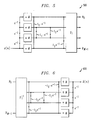
- any cosine modulated filter bank can be represented by a formulation using Zero-Delay and Maximum-Delay matrices, as described in G. Schuller & T. Karp, "Modulated Filter Banks with Arbitrary System Delay: Efficient Implementations and the Time-Varying Case,” Trans. on Signal Processing, V. 48, No. 3 (March, 2000), incorporated by reference herein. This leads to a structure, which consists of nested two band sub-structures.
- FIG. 5 shows an example for a four band filter bank 500
- FIG. 6 shows the corresponding four band synthesis filter bank 600 with reduced aliasing
- T 1 is an M 1 ⁇ M 1 Discrete Cosine Transfom (DCT) type 4, in this case, having a size 4 ⁇ 4
- T 1 -1 is an M 1 ⁇ M 1 Inverse Discrete Cosine Transfom (IDCT) type 4, in this case, having a size 4 ⁇ 4. See, G. Schuller & T. Karp, referenced above.
- DCT Discrete Cosine Transfom
- IDCT Inverse Discrete Cosine Transfom
- FIG. 7 shows a two band alias reduction filter 700 generated from the four band synthesis filter bank 600 of FIG. 6.
- T 2 is a 2 ⁇ 2 DCT.
- the resulting two band filter bank has similar frequency responses (up to the scaling), and hence can be used for the alias reduction.
- the values l of the structure determine the resulting window function or baseband prototype of the filter bank. Since this smaller filter bank is obtained by "downsampling" the structure, its window function is obtained by downsampling the window function of the first stage filter bank in a certain way. Since the sub-structures are symmetric around the center of a block of length M 1 , the resulting downsampling of the window function appears in an analog fashion, downsampling each interval of length M 1 of the window function symmetric around each intervals center. For example, assume the first stage filter bank has four bands (M 1 equals 4), and its window function has the form: 1, 2, 3, 4, 4, 3, 2, 1
- the window function of the second stage can be obtained by symmetric downsampling in each block of four samples, as in the following: 2, 3, 3, 2
- this downsampling rule is also valid for these types of filter banks.
- the window function obtained by this non-uniform symmetric downsampling automatically leads to a filter bank with reduced aliasing, and it also reduces the aliasing after the first stage.
- FIG. 3 shows an enlargement of a particular band of a uniform 1024 band filter bank, without cascading. With the stacked cascaded filter bank, the goal is a frequency response similar to this after the final stage.
- FIG. 2 shows an enlargement of the same channel but for a traditional cascaded filter bank, with 128 bands in the first stage and 8 bands following in each subband in the next stage. The aliasing is easy to see as the high peaks, other than the main lobe.
- the structure of a 128 band alias reduction filter bank is "downsampled" to obtain an eight band alias reduction filter bank for reducing the aliasing across eight neighboring bands.
- This downsampling leads to a structure with a 128 band analysis filter bank in the first stage, followed by an eight band alias reduction filter bank for alias reduction in the second stage, followed by a 64 band analysis filter bank in the final stages.
- the overall alias reduction filter bank for this structure contains the reverse steps.
Landscapes
- Physics & Mathematics (AREA)
- Engineering & Computer Science (AREA)
- Computer Hardware Design (AREA)
- Mathematical Physics (AREA)
- Compression, Expansion, Code Conversion, And Decoders (AREA)
- Cable Transmission Systems, Equalization Of Radio And Reduction Of Echo (AREA)
- Magnetic Resonance Imaging Apparatus (AREA)
Abstract
Description
1, 2, 3, 4, 4, 3, 2, 1
2, 3, 3, 2
Claims (20)
- A method for reducing aliasing between neighboring subbands in a cascaded filter bank, comprising the steps of:filtering a signal to produce a plurality of frequency components using a plurality of subbands in a first filter bank;adding said frequency components using an alias reduction filter bank at an output of said subbands in said first filter bank; andfiltering said added frequency components using a plurality of subbands in a second filter bank.
- The method of claim 1, wherein the magnitude response of said alias reduction filter bank is approximately equal to a magnitude response of a synthesis filter bank of the first filter bank.
- The method of claim 1, wherein the phase characteristics of said alias reduction filter bank is approximately equal to a magnitude response of a synthesis filter bank of the first filter bank.
- The method of claim 1, wherein said plurality of subbands in said first filter bank comprise M1 bands, and said alias reduction filter bank has M2 bands and said alias reduction filter bank has a frequency response approximately equal to the frequency response of a synthesis filter bank in said first filter bank scaled by the ratio of M1/M2.
- The method of claim 1, wherein said alias reduction filter bank is a cosine modulated filter bank and contains only every M1/M2 th sub-structure.
- A cascaded filter bank, comprising:a first filter bank comprised of a plurality of subbands for filtering a signal into a plurality of frequency components;an alias reduction filter bank at an output of said first filter bank, said alias reduction filter bank adding said frequency components; anda second filter bank connected to said alias reduction filter, said second filter bank comprised of a plurality of subbands for filtering said frequency components produced by said alias reduction filter bank.
- The cascaded filter bank of claim 6, wherein the magnitude response of said alias reduction filter bank is approximately equal to a magnitude response of a synthesis filter bank of the first filter bank.
- The cascaded filter bank of claim 6, wherein the phase characteristics of said alias reduction filter bank is approximately equal to a magnitude response of a synthesis filter bank of the first filter bank.
- The cascaded filter bank of claim 6, wherein said plurality of subbands in said first filter bank comprise M1 bands, and said alias reduction filter bank has M2 bands and said alias reduction filter bank has a frequency response approximately equal to the frequency response of a synthesis filter bank in said first filter bank scaled by the ratio of M1/M2.
- The cascaded filter bank of claim 6, wherein said alias reduction filter bank is a cosine modulated filter bank and contains only every M1/M2 th sub-structure.
- A method for reducing aliasing between neighboring subbands in a cascaded filter bank, comprising the steps of:filtering a signal using a first filter bank to produce M1 subbands;adding M2 subbands of said M1 subbands using an alias reduction filter bank; andfiltering said added M2 subbands using a plurality of subbands in a second filter bank.
- The method of claim 11, wherein the magnitude response of said alias reduction filter bank is approximately equal to a magnitude response of a synthesis filter bank of the first filter bank.
- The method of claim 11, wherein the phase characteristics of said alias reduction filter bank is approximately equal to a magnitude response of a synthesis filter bank of the first filter bank.
- The method of claim 11, wherein said alias reduction filter bank has a frequency response approximately equal to the frequency response of a synthesis filter bank in said first filter bank scaled by the ratio of M1/M2.
- The method of claim 11, wherein said alias reduction filter bank is a cosine modulated filter bank and contains only every M1/M2 th sub-structure.
- A cascaded filter bank, comprising:a first filter bank for filtering a signal into M1 subbands;an alias reduction filter bank for adding M2 subbands of said M1 subbands; anda second filter bank for filtering said M2 subbands produced by said alias reduction filter bank.
- The cascaded filter bank of claim 16, wherein the magnitude response of said alias reduction filter bank is approximately equal to a magnitude response of a synthesis filter bank of the first filter bank.
- The cascaded filter bank of claim 16, wherein the phase characteristics of said alias reduction filter bank is approximately equal to a magnitude response of a synthesis filter bank of the first filter bank.
- The cascaded filter bank of claim 16, wherein said plurality of subbands in said first filter bank comprise M1 bands, and said alias reduction filter bank has M2 bands and said alias reduction filter bank has a frequency response approximately equal to the frequency response of a synthesis filter bank in said first filter bank scaled by the ratio of M1/M2.
- The cascaded filter bank of claim 16, wherein said alias reduction filter bank is a cosine modulated filter bank and contains only every M1/M2 th sub-structure.
Applications Claiming Priority (2)
| Application Number | Priority Date | Filing Date | Title |
|---|---|---|---|
| US586069 | 2000-06-02 | ||
| US09/586,069 US6718300B1 (en) | 2000-06-02 | 2000-06-02 | Method and apparatus for reducing aliasing in cascaded filter banks |
Publications (3)
| Publication Number | Publication Date |
|---|---|
| EP1160977A2 true EP1160977A2 (en) | 2001-12-05 |
| EP1160977A3 EP1160977A3 (en) | 2004-12-08 |
| EP1160977B1 EP1160977B1 (en) | 2018-08-01 |
Family
ID=24344180
Family Applications (1)
| Application Number | Title | Priority Date | Filing Date |
|---|---|---|---|
| EP01304838.4A Expired - Lifetime EP1160977B1 (en) | 2000-06-02 | 2001-06-01 | Method and apparatus for reducing aliasing in cascaded filter banks |
Country Status (5)
| Country | Link |
|---|---|
| US (1) | US6718300B1 (en) |
| EP (1) | EP1160977B1 (en) |
| JP (2) | JP2002055698A (en) |
| KR (1) | KR20010110176A (en) |
| TW (1) | TW517222B (en) |
Cited By (5)
| Publication number | Priority date | Publication date | Assignee | Title |
|---|---|---|---|---|
| US7069212B2 (en) | 2002-09-19 | 2006-06-27 | Matsushita Elecric Industrial Co., Ltd. | Audio decoding apparatus and method for band expansion with aliasing adjustment |
| WO2008049590A1 (en) | 2006-10-25 | 2008-05-02 | Fraunhofer-Gesellschaft zur Förderung der angewandten Forschung e.V. | Apparatus and method for generating audio subband values and apparatus and method for generating time-domain audio samples |
| EP1927981A1 (en) * | 2006-12-01 | 2008-06-04 | Harman/Becker Automotive Systems GmbH | Spectral refinement of audio signals |
| RU2426178C2 (en) * | 2006-10-18 | 2011-08-10 | Фраунхофер-Гезельшафт Цур Фёрдерунг Дер Ангевандтен Форшунг Е.Ф. | Analysis filterbank, synthesis filterbank, encoder, decoder, mixer and conferencing system |
| USRE50158E1 (en) | 2006-10-25 | 2024-10-01 | Fraunhofer-Gesellschaft Zur Foerderung Der Angewandten Forschung E.V. | Apparatus and method for generating audio subband values and apparatus and method for generating time-domain audio samples |
Families Citing this family (9)
| Publication number | Priority date | Publication date | Assignee | Title |
|---|---|---|---|---|
| SE0202159D0 (en) | 2001-07-10 | 2002-07-09 | Coding Technologies Sweden Ab | Efficientand scalable parametric stereo coding for low bitrate applications |
| WO2003046891A1 (en) | 2001-11-29 | 2003-06-05 | Coding Technologies Ab | Methods for improving high frequency reconstruction |
| ES2261974T3 (en) | 2002-08-01 | 2006-11-16 | Matsushita Electric Industrial Co., Ltd. | DECODING PARATO AND AUDIO DECODING METHOD BASED ON A SPECTRAL BAND DUPLICATION. |
| SE0202770D0 (en) * | 2002-09-18 | 2002-09-18 | Coding Technologies Sweden Ab | Method of reduction of aliasing is introduced by spectral envelope adjustment in real-valued filterbanks |
| US7164724B2 (en) * | 2002-09-25 | 2007-01-16 | Matsushita Electric Industrial Co., Ltd. | Communication apparatus |
| KR100881698B1 (en) | 2007-10-05 | 2009-02-06 | 한국과학기술원 | How to remove aliasing in subband adaptive filtering system and subband adaptive filtering system without aliasing |
| CN102545833A (en) * | 2012-02-13 | 2012-07-04 | 西南民族大学 | Two-channel linear phase wavelet filter bank with two-level polyphase substructure |
| CN111262555B (en) * | 2020-03-09 | 2023-12-08 | 西安电子科技大学 | Design method of cascade modulation filter bank channelizer suitable for high-throughput satellites |
| EP4211680A1 (en) * | 2020-09-07 | 2023-07-19 | Kiwip Technologies SAS | Secure communication system with speaker recognition by voice biometrics for user groups such as family groups |
Family Cites Families (7)
| Publication number | Priority date | Publication date | Assignee | Title |
|---|---|---|---|---|
| US5436940A (en) * | 1992-06-11 | 1995-07-25 | Massachusetts Institute Of Technology | Quadrature mirror filter banks and method |
| US5606319A (en) * | 1995-08-07 | 1997-02-25 | Motorola, Inc. | Method and apparatus for interpolation and noise shaping in a signal converter |
| JPH09148937A (en) * | 1995-11-21 | 1997-06-06 | Sony Corp | Encoding processing method, decoding processing method, encoding processing device, and decoding processing device |
| US5852806A (en) * | 1996-03-19 | 1998-12-22 | Lucent Technologies Inc. | Switched filterbank for use in audio signal coding |
| SE512719C2 (en) * | 1997-06-10 | 2000-05-02 | Lars Gustaf Liljeryd | A method and apparatus for reducing data flow based on harmonic bandwidth expansion |
| US6144937A (en) * | 1997-07-23 | 2000-11-07 | Texas Instruments Incorporated | Noise suppression of speech by signal processing including applying a transform to time domain input sequences of digital signals representing audio information |
| US6029126A (en) * | 1998-06-30 | 2000-02-22 | Microsoft Corporation | Scalable audio coder and decoder |
-
2000
- 2000-06-02 US US09/586,069 patent/US6718300B1/en not_active Expired - Lifetime
-
2001
- 2001-06-01 JP JP2001166291A patent/JP2002055698A/en active Pending
- 2001-06-01 KR KR1020010030832A patent/KR20010110176A/en not_active Ceased
- 2001-06-01 TW TW090113367A patent/TW517222B/en not_active IP Right Cessation
- 2001-06-01 EP EP01304838.4A patent/EP1160977B1/en not_active Expired - Lifetime
-
2011
- 2011-02-28 JP JP2011041786A patent/JP2011176829A/en active Pending
Cited By (26)
| Publication number | Priority date | Publication date | Assignee | Title |
|---|---|---|---|---|
| US7069212B2 (en) | 2002-09-19 | 2006-06-27 | Matsushita Elecric Industrial Co., Ltd. | Audio decoding apparatus and method for band expansion with aliasing adjustment |
| USRE45277E1 (en) | 2006-10-18 | 2014-12-02 | Fraunhofer-Gesellschaft Zur Foerderung Der Angewandten Forschung E.V. | Analysis filterbank, synthesis filterbank, encoder, de-coder, mixer and conferencing system |
| USRE45526E1 (en) | 2006-10-18 | 2015-05-19 | Fraunhofer-Gesellschaft Zur Foerderung Der Angewandten Forschung E.V. | Analysis filterbank, synthesis filterbank, encoder, de-coder, mixer and conferencing system |
| USRE45339E1 (en) | 2006-10-18 | 2015-01-13 | Fraunhofer-Gesellschaft Zur Foerderung Der Angewandten Forschung E.V. | Analysis filterbank, synthesis filterbank, encoder, de-coder, mixer and conferencing system |
| USRE45294E1 (en) | 2006-10-18 | 2014-12-16 | Fraunhofer-Gesellschaft Zur Foerderung Der Angewandten Forschung E.V. | Analysis filterbank, synthesis filterbank, encoder, de-coder, mixer and conferencing system |
| USRE45276E1 (en) | 2006-10-18 | 2014-12-02 | Fraunhofer-Gesellschaft Zur Foerderung Der Angewandten Forschung E.V. | Analysis filterbank, synthesis filterbank, encoder, de-coder, mixer and conferencing system |
| RU2426178C2 (en) * | 2006-10-18 | 2011-08-10 | Фраунхофер-Гезельшафт Цур Фёрдерунг Дер Ангевандтен Форшунг Е.Ф. | Analysis filterbank, synthesis filterbank, encoder, decoder, mixer and conferencing system |
| CN101405791B (en) * | 2006-10-25 | 2012-01-11 | 弗劳恩霍夫应用研究促进协会 | Apparatus and method for generating audio subband values and apparatus and method for generating time-domain audio samples |
| USRE49999E1 (en) | 2006-10-25 | 2024-06-04 | Fraunhofer-Gesellschaft Zur Foerderung Der Angewandten Forschung E.V. | Apparatus and method for generating audio subband values and apparatus and method for generating time-domain audio samples |
| US8452605B2 (en) | 2006-10-25 | 2013-05-28 | Fraunhofer-Gesellschaft Zur Foerderung Der Angewandten Forschung E.V. | Apparatus and method for generating audio subband values and apparatus and method for generating time-domain audio samples |
| US8775193B2 (en) | 2006-10-25 | 2014-07-08 | Fraunhofer-Gesellschaft Zur Foerderung Der Angewandten Forschung E.V. | Apparatus and method for generating audio subband values and apparatus and method for generating time-domain audio samples |
| USRE50194E1 (en) | 2006-10-25 | 2024-10-29 | Fraunhofer-Gesellschaft Zur Foerderung Der Angewandten Forschung E.V. | Apparatus and method for generating audio subband values and apparatus and method for generating time-domain audio samples |
| RU2420815C2 (en) * | 2006-10-25 | 2011-06-10 | Фраунхофер-Гезелльшафт Цур Фердерунг Дер Ангевандтен Форшунг Е.Ф. | Device and method of generating audio signal subband values and device and method of generating audio signal readings in time domain |
| RU2411645C2 (en) * | 2006-10-25 | 2011-02-10 | Фраунхофер-Гезелльшафт Цур Фердерунг Дер Ангевандтен Форшунг Е.Ф. | Device and method to generate values of subbands of sound signal and device and method to generate audio counts of time area |
| USRE50157E1 (en) | 2006-10-25 | 2024-10-01 | Fraunhofer-Gesellschaft Zur Foerderung Der Angewandten Forschung E.V. | Apparatus and method for generating audio subband values and apparatus and method for generating time-domain audio samples |
| WO2008049590A1 (en) | 2006-10-25 | 2008-05-02 | Fraunhofer-Gesellschaft zur Förderung der angewandten Forschung e.V. | Apparatus and method for generating audio subband values and apparatus and method for generating time-domain audio samples |
| US8438015B2 (en) | 2006-10-25 | 2013-05-07 | Fraunhofer-Gesellschaft Zur Foerderung Der Angewandten Forschung E.V. | Apparatus and method for generating audio subband values and apparatus and method for generating time-domain audio samples |
| USRE50009E1 (en) | 2006-10-25 | 2024-06-11 | Fraunhofer-Gesellschaft Zur Foerderung Der Angewandten Forschung E.V. | Apparatus and method for generating audio subband values and apparatus and method for generating time-domain audio samples |
| USRE50015E1 (en) | 2006-10-25 | 2024-06-18 | Fraunhofer-Gesellschaft Zur Foerderung Der Angewandten Forschung E.V. | Apparatus and method for generating audio subband values and apparatus and method for generating time-domain audio samples |
| USRE50054E1 (en) | 2006-10-25 | 2024-07-23 | Fraunhofer-Gesellschaft Zur Foerderung Der Angewandten Forschung E.V. | Apparatus and method for generating audio subband values and apparatus and method for generating time-domain audio samples |
| USRE50132E1 (en) | 2006-10-25 | 2024-09-17 | Fraunhofer-Gesellschaft Zur Foerderung Der Angewandten Forschung E.V. | Apparatus and method for generating audio subband values and apparatus and method for generating time-domain audio samples |
| USRE50144E1 (en) | 2006-10-25 | 2024-09-24 | Fraunhofer-Gesellschaft Zur Foerderung Der Angewandten Forschung E.V. | Apparatus and method for generating audio subband values and apparatus and method for generating time-domain audio samples |
| USRE50159E1 (en) | 2006-10-25 | 2024-10-01 | Fraunhofer-Gesellschaft Zur Foerderung Der Angewandten Forschung E.V. | Apparatus and method for generating audio subband values and apparatus and method for generating time-domain audio samples |
| USRE50158E1 (en) | 2006-10-25 | 2024-10-01 | Fraunhofer-Gesellschaft Zur Foerderung Der Angewandten Forschung E.V. | Apparatus and method for generating audio subband values and apparatus and method for generating time-domain audio samples |
| EP1927981A1 (en) * | 2006-12-01 | 2008-06-04 | Harman/Becker Automotive Systems GmbH | Spectral refinement of audio signals |
| US8190426B2 (en) | 2006-12-01 | 2012-05-29 | Nuance Communications, Inc. | Spectral refinement system |
Also Published As
| Publication number | Publication date |
|---|---|
| JP2011176829A (en) | 2011-09-08 |
| TW517222B (en) | 2003-01-11 |
| US6718300B1 (en) | 2004-04-06 |
| EP1160977B1 (en) | 2018-08-01 |
| KR20010110176A (en) | 2001-12-12 |
| EP1160977A3 (en) | 2004-12-08 |
| JP2002055698A (en) | 2002-02-20 |
Similar Documents
| Publication | Publication Date | Title |
|---|---|---|
| JP2011176829A (en) | Method and apparatus for reducing aliasing in cascaded filter banks | |
| EP0797313B1 (en) | Switched filterbank for use in audio signal coding | |
| US7242710B2 (en) | Aliasing reduction using complex-exponential modulated filterbanks | |
| Sinha et al. | Audio compression at low bit rates using a signal adaptive switched filterbank | |
| US5451954A (en) | Quantization noise suppression for encoder/decoder system | |
| CN1957535A (en) | Digit transducer device | |
| Black et al. | Computationally efficient wavelet packet coding of wide-band stereo audio signals | |
| Schuller et al. | A new algorithm for efficient low delay filter bank design | |
| CA2118915C (en) | Process for reducing frequency interlacing during acoustic or optical signal transmission and/or recording | |
| Sodagar et al. | A class of time-varying wavelet transforms | |
| DE60210479T2 (en) | AUDIO CODERS WITH IRREGULAR FILTER BANK | |
| Schuller | A low delay filter bank for audio coding with reduced pre-echoes | |
| Schuller et al. | A method for alias reduction in cascaded filter banks | |
| Tang et al. | Spectral analysis of subband filtered signals | |
| Trautmann et al. | GenLOT-design and application for transform-based image coding | |
| Tran et al. | Generalized lapped orthogonal transform with unequal-length basis functions | |
| Cheung et al. | Incorporation of biorthogonality into lapped transforms for audio compression | |
| Mau et al. | Time-varying orthogonal filter banks without transient filters | |
| Purat et al. | A new orthonormal wavelet packet decomposition for audio coding using frequency-varying modulated lapped transforms | |
| Schuller | Time-varying filter banks with low delay for audio coding | |
| US6507300B1 (en) | Variable rate decimator | |
| Xie et al. | M-band perfect-reconstruction linear-phase filter banks | |
| Phoong et al. | Robust M-channel biorthogonal filter banks | |
| JP3033158B2 (en) | Digital signal encoder | |
| Chen et al. | Optimal design of deconvolution filters for stochastic multirate signal systems |
Legal Events
| Date | Code | Title | Description |
|---|---|---|---|
| PUAI | Public reference made under article 153(3) epc to a published international application that has entered the european phase |
Free format text: ORIGINAL CODE: 0009012 |
|
| AK | Designated contracting states |
Kind code of ref document: A2 Designated state(s): AT BE CH CY DE DK ES FI FR GB GR IE IT LI LU MC NL PT SE TR |
|
| AX | Request for extension of the european patent |
Free format text: AL;LT;LV;MK;RO;SI |
|
| PUAL | Search report despatched |
Free format text: ORIGINAL CODE: 0009013 |
|
| AK | Designated contracting states |
Kind code of ref document: A3 Designated state(s): AT BE CH CY DE DK ES FI FR GB GR IE IT LI LU MC NL PT SE TR |
|
| AX | Request for extension of the european patent |
Extension state: AL LT LV MK RO SI |
|
| 17P | Request for examination filed |
Effective date: 20050523 |
|
| AKX | Designation fees paid |
Designated state(s): GB |
|
| REG | Reference to a national code |
Ref country code: DE Ref legal event code: 8566 |
|
| RAP1 | Party data changed (applicant data changed or rights of an application transferred) |
Owner name: AVAGO TECHNOLOGIES GENERAL IP (SINGAPORE) PTE. LTD |
|
| STAA | Information on the status of an ep patent application or granted ep patent |
Free format text: STATUS: EXAMINATION IS IN PROGRESS |
|
| GRAP | Despatch of communication of intention to grant a patent |
Free format text: ORIGINAL CODE: EPIDOSNIGR1 |
|
| STAA | Information on the status of an ep patent application or granted ep patent |
Free format text: STATUS: GRANT OF PATENT IS INTENDED |
|
| INTG | Intention to grant announced |
Effective date: 20180313 |
|
| GRAS | Grant fee paid |
Free format text: ORIGINAL CODE: EPIDOSNIGR3 |
|
| GRAA | (expected) grant |
Free format text: ORIGINAL CODE: 0009210 |
|
| STAA | Information on the status of an ep patent application or granted ep patent |
Free format text: STATUS: THE PATENT HAS BEEN GRANTED |
|
| AK | Designated contracting states |
Kind code of ref document: B1 Designated state(s): GB |
|
| REG | Reference to a national code |
Ref country code: GB Ref legal event code: FG4D |
|
| RAP2 | Party data changed (patent owner data changed or rights of a patent transferred) |
Owner name: AVAGO TECHNOLOGIES INTERNATIONAL SALES PTE. LIMITE |
|
| PLBE | No opposition filed within time limit |
Free format text: ORIGINAL CODE: 0009261 |
|
| STAA | Information on the status of an ep patent application or granted ep patent |
Free format text: STATUS: NO OPPOSITION FILED WITHIN TIME LIMIT |
|
| 26N | No opposition filed |
Effective date: 20190503 |
|
| PGFP | Annual fee paid to national office [announced via postgrant information from national office to epo] |
Ref country code: GB Payment date: 20190627 Year of fee payment: 19 |
|
| GBPC | Gb: european patent ceased through non-payment of renewal fee |
Effective date: 20200601 |
|
| PG25 | Lapsed in a contracting state [announced via postgrant information from national office to epo] |
Ref country code: GB Free format text: LAPSE BECAUSE OF NON-PAYMENT OF DUE FEES Effective date: 20200601 |