EP1160955A2 - Vibrator motor holder - Google Patents
Vibrator motor holder Download PDFInfo
- Publication number
- EP1160955A2 EP1160955A2 EP01112114A EP01112114A EP1160955A2 EP 1160955 A2 EP1160955 A2 EP 1160955A2 EP 01112114 A EP01112114 A EP 01112114A EP 01112114 A EP01112114 A EP 01112114A EP 1160955 A2 EP1160955 A2 EP 1160955A2
- Authority
- EP
- European Patent Office
- Prior art keywords
- cavity
- electrical
- housing
- electrical device
- electrical connector
- Prior art date
- Legal status (The legal status is an assumption and is not a legal conclusion. Google has not performed a legal analysis and makes no representation as to the accuracy of the status listed.)
- Withdrawn
Links
Images




Classifications
-
- H—ELECTRICITY
- H04—ELECTRIC COMMUNICATION TECHNIQUE
- H04M—TELEPHONIC COMMUNICATION
- H04M1/00—Substation equipment, e.g. for use by subscribers
- H04M1/02—Constructional features of telephone sets
- H04M1/0202—Portable telephone sets, e.g. cordless phones, mobile phones or bar type handsets
- H04M1/026—Details of the structure or mounting of specific components
-
- H—ELECTRICITY
- H02—GENERATION; CONVERSION OR DISTRIBUTION OF ELECTRIC POWER
- H02K—DYNAMO-ELECTRIC MACHINES
- H02K5/00—Casings; Enclosures; Supports
-
- H—ELECTRICITY
- H02—GENERATION; CONVERSION OR DISTRIBUTION OF ELECTRIC POWER
- H02K—DYNAMO-ELECTRIC MACHINES
- H02K2211/00—Specific aspects not provided for in the other groups of this subclass relating to measuring or protective devices or electric components
- H02K2211/03—Machines characterised by circuit boards, e.g. pcb
-
- H—ELECTRICITY
- H02—GENERATION; CONVERSION OR DISTRIBUTION OF ELECTRIC POWER
- H02K—DYNAMO-ELECTRIC MACHINES
- H02K5/00—Casings; Enclosures; Supports
- H02K5/04—Casings or enclosures characterised by the shape, form or construction thereof
- H02K5/22—Auxiliary parts of casings not covered by groups H02K5/06-H02K5/20, e.g. shaped to form connection boxes or terminal boxes
- H02K5/225—Terminal boxes or connection arrangements
-
- H—ELECTRICITY
- H02—GENERATION; CONVERSION OR DISTRIBUTION OF ELECTRIC POWER
- H02K—DYNAMO-ELECTRIC MACHINES
- H02K7/00—Arrangements for handling mechanical energy structurally associated with dynamo-electric machines, e.g. structural association with mechanical driving motors or auxiliary dynamo-electric machines
- H02K7/06—Means for converting reciprocating motion into rotary motion or vice versa
- H02K7/061—Means for converting reciprocating motion into rotary motion or vice versa using rotary unbalanced masses
Definitions
- the invention relates to vibration motor holders and in particular to a vibration motor or vibrator holder integrally formed on an I/O connector of a wireless telephone.
- Vibration motors are well known in wireless telephones. They are typically used in situations where the user does not want an incoming call to activate an audible ringer and therefore switches the phone to the vibration mode. In the vibration mode an incoming call activates activates the motor and the resultant vibration is felt by the user as an indication of the incoming call.
- Known vibration motors are typically housed within the casing by securing them with clips to corresponding holders within the casing.
- Other known holders not specifically designed for vibrator motors include those described in US 5, 211,579 and US 5, 830,007 of the present assignee, and US 5, 586, 907 and US 5,, 980, 309 assigned to the Whitaker Corporation. These all describe a connector for mounting a cylindrical electrical device.
- a battery holder or housing is described.
- the holder is adapted to contain a cylindrical battery, the battery being inserted into the holder in a direction perpendicular to its longitudinal axis.
- the battery is held in place at one end by a round shoulder overhanging one end of the battery and at the other end by a detent in a flexible terminal which engages a projection at the opposite end of the battery.
- US 5, 586, 907 describes an alternative battery connector, this connector adapted to constrain a disk shaped battery.
- the battery is inserted in a direction parallel to its longitudinal axis.
- the battery is held in place by two opposed pliable locking arms which clip over the cylindrical wall of the battery.
- a microphone device is inserted in a direction parallel to its longitudinal axis.
- a flexible locking arm contacts the circumferential surface of the microphone forcing the microphone into an interference fit in the housing.
- the locking arm also has a flange overhanging a portion of the flat surface of the microphone.
- the invention which solves the problems in the prior art includes a housing for an electrical device where the housing is mountable within a wireless telephone.
- The has a device insertion cavity defined by side walls and a stop extending into the cavity.
- the inner surface of the side walls forming a cross section substantially corresponding to the cross section of the outer surface of the device to be housed.
- the cavity is adapted to receive and constrain at least a portion of the electrical device.
- the device may be inserted into the cavity through an entry port.
- a retaining device is provided to be moveable into a position that obstructs at least a portion of the entry port, thereby retaining the inserted device within the insertion cavity. When the retaining device is moved to an obstructing position, the inserted device is contained snugly within the cavity providing a secure retaining region for the electrical device.
- the invention additionally provides an electrical connector for mounting an electrical device, including a housing having an electrical device insertion cavity defined by side walls and a stop extending into the cavity.
- the inner surface of the walls forming a cross section substantially corresponding to the cross section of the peripheral surface of the electrical device so that the device can be supported in the cavity.
- the cavity having an entry port through which the electrical device may be inserted.
- a locking piece is insertable into a slot in the housing adjacent to the entry port. When the locking piece is inserted into the slot at least a portion of the entry port is obstructed preventing the electrical device from moving out of the device insertion cavity, thereby restraining the device in a contained position.
- the electrical device is preferably a vibration motor adapted to vibrate when activated and is preferably mountable within a wireless telephone body, the mounting of the electrical connector providing a fixed and secure retention of the electrical connector against the telephone body, such that any vibration of the vibration motor within its housing is transmitted efficiently to the telephone body.
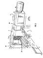
- Figures 1 to 4 show an electrical connector 1 for mounting an electrical device in accordance with the present invention.
- Figure 1 shows the connector without the electrical device mounted therein.
- the connector has a housing 2 having an electrical device insertion cavity 3.
- Walls 4 of the cavity have an inner surface which form a cross section substantially corresponding to a cross section of a peripheral surface of the electrical device 8 to be inserted into the cavity 3, so that the device can be supported in the cavity.
- the cavity walls 4 defining in one face of the cavity an entry port 5 through which the electrical device may be placed into the cavity 3.
- a stop 35 extending into or defining an end of the cavity ensures that, when the device is fully inserted into the cavity, terminals on the bottom of the device 8 (not shown) will be in proper alignment with power terminals 37 which extend into the cavity 3.
- a locking piece 6 is insertable into a slot 7 in the housing 2 adjacent to the entry port 5, the insertion of the locking piece 6 into the slot 7 obstructing at least a portion of the entry port 5 .
- the locking piece 6 is formed from metal, though any suitable alternative material may also be used.
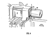
- Figures 2 to 4 show a portion of the connector of Figure 1 with an electrical device 8 in varying degrees of insertion into the cavity 3.
- the electrical device 8 is preferably a vibration motor having a motor body 8a, which is surrounded by a rubber sleeve, and an off-center shaft 8b which causes the vibration when the motor is activated.
- An example of the type of vibration or vibrator motor is that manufactured by the Matsushita Electric Industry Company Limited.
- the locking piece 6 is positioned within the slot 7, but not moved into a position whereby it obstructs the entry port 5.
- the locking piece 6 may be slid across the entry port 5 in the slot 7 so as to obstruct a portion of the entry port.
- the obstruction of the entry port prevents the vibration motor contained therein from falling or slipping out of the cavity 3, thereby holding the device in a contained position.
- the electrical device 1 is preferably an input/ output (I/O) connector for use in a wireless telephone. As such it incorporates a plurality of functional components in addition to the housing for the vibration motor. These typically include a recharger pads 9 adapted to cooperate with a power supply for recharging the wireless telephone, a housing 10 for a microphone (not shown), and a plurality of terminal connectors 11 for establishing an electrical connection between electrical device 1 and the remaining portion of the wireless telephone.
- the electrical device 1 is also provided with engagement means 12 adapted to secure the electrical device within the wireless telephone.
- the engagement means 12 are typically threaded apertures which co-operate with a screw or nut (not shown) so as to secure and retain the electrical device within the telephone.
- a DC power port 30 adapted for car recharging situations and/or a stereo jack connector 31 may additionally be provided.
- Figure 5 shows the electrical device 1 with a portion of a flexible cable 13 mounted thereon.
- the flexible cable 13 is provided with a plurality of connection apertures 14 electrically connected to conductive strips (not shown) which are part of the cable 13.
- the apertures 14 are adapted to be soldered to terminals 11 on the device 1.
- the flexible cable electrically connects the electrical device 1 with the remainder of the wireless telephone (not shown). It will be appreciated by those skilled in the art that a small bend radius in the cable will take up less volume.
- the flexible cable 13 may additionally be provided with a plurality of bend apertures 15. These apertures 15 enable a bend region to be formed along the axis of the apertures 15. The provision of the apertures ensures that the bend region is formed with a small bend radius and thus take up less volume.
- Figure 6 shows the combined electrical device 1 and flexible cable 13 of Figure 4 with a bend region or bend portion 16 formed therein.
- the bend portion 16 is formed with a small bend radius, typically in the range of 0.5 mm to 1.0 mm, and more preferably about 0.8 mm.
- the provision of the bend region 16 allows the connection region of the device 1 and connector 13 to be formed substantially perpendicular to a main portion 13a of the flexible connector 13, which is advantageous when mounting the device within an interior portion of a wireless phone casing 18, as shown in Figures 7 and 8.
- the device 1 is mounted and retained against a base portion 19 of the phone casing 18, with mounting screws 20 co-operating with the engagement apertures 12 of the electrical device 1.
- the electrical device 1 with the vibrator motor 8 previously secured therein, is positioned within the phone casing 18, and retained therein by passing the mounting screws 20 though the base portion 19 and threading them through the co-operating engagement apertures 12 of the electrical device.
- the electrical device 1 is thereby securely retained within the phone casing 18.
Landscapes
- Engineering & Computer Science (AREA)
- Power Engineering (AREA)
- Signal Processing (AREA)
- Telephone Set Structure (AREA)
- Apparatuses For Generation Of Mechanical Vibrations (AREA)
- Motor Or Generator Frames (AREA)
- Connection Of Motors, Electrical Generators, Mechanical Devices, And The Like (AREA)
- Mobile Radio Communication Systems (AREA)
Abstract
Description
Claims (22)
- A housing for an electrical device, the housing being mountable within a wireless telephone, the housing comprising:a device insertion cavity having side walls and a stop extending into the cavity, the inner surface of the walls forming a cross section substantially corresponding to the cross section of the outer surface of the device to be housed, such that the cavity is adapted to receive and constrain at least a portion of the device within the cavity;an entry port through which the device may be inserted into the cavity; anda retaining device, the retaining device adapted to be moveable into a position that obstructs at least a portion of the entry port, thereby retaining with said stop an inserted device within the insertion cavity.
- The housing as claimed in claim 1 wherein the electrical device is a vibrator motor.
- The housing as claimed in claim 1 wherein the retaining device is a latch, adapted to be moveable between an open position where the entry port is unobstructed and the electrical device is free to move into and out of the cavity and a closed position wherein the entry port is at least partially obstructed thereby preventing the movement of the electrical device into or out of the cavity.
- The housing as claimed in claim 3 further comprising a channel, at least a portion of the latch being slideable within the channel between the open and closed positions.
- The housing as claimed in claim 1 further comprising terminals adapted to be electrically engagable with corresponding terminals on the electrical device, the terminals being positioned adjacent the cavity such that on insertion of the electrical device fully into the cavity, when a leading edge of the electrical device engages the stop, the terminals adjacent the cavity and the terminals on the electrical device are in electrical engagement.
- The housing as claimed in claim 1 wherein the housing is integrally formed on an electrical connector, the electrical connector having mounting means adapted to effect the mounting of the housing in the telephone.
- The housing as claimed in claim 6 wherein the electrical connector further comprising mounting means adapted to receive a microphone.
- The housing as claimed in claim 6 wherein the electrical connector further comprises an electrical power connector, the electrical power connector adapted to be connectable with a power supply.
- The housing as claimed in claim 8 wherein the power supply is a battery recharging supply, the connection of the power supply with the electrical power connector effecting a re-charging of a battery within the wireless telephone.
- An electrical connector for mounting an electrical device, comprising:a housing having an electrical device insertion cavity with side walls and a stop extending into the cavity, the inner surface of the side walls forming a cross section substantially corresponding to a cross section of a peripheral surface of the electrical device so that the device can be supported in the cavity;the cavity walls defining in one face of the cavity an entry port through which the electrical device may be placed into the cavity; anda locking piece insertable into a slot in the housing adjacent to the entry port, the insertion of the locking piece into the slot obstructing at least a portion of the entry port and preventing the electrical device from moving out of the device insertion cavity, thereby restraining with the stop the device in a contained position.
- The electrical connector as claimed in claim 10 further comprising terminals adjacent the cavity adapted to engage terminals on the electrical device, the terminals adjacent the cavity being positioned such that on insertion of the electrical device fully into the cavity, when a leading edge of the electrical device engages the stop, the terminals adjacent the cavity and the terminals on the electrical device are in electrical engagement.
- The electrical connector of claims 10 wherein said locking piece is slideable within the slot between an open position whereby the entry port is not obstructed and the electrical device can be inserted and removed from the device insertion cavity, and a closed position whereby the entry port is obstructed.
- The electrical connector of claim 12 wherein said locking piece is made of stamped and formed metal.
- The electrical connector of claims 12 wherein said locking piece is formed integral with the housing.
- The electrical connector as claimed in claim 10 further comprising mounting means adapted to effect the mounting of the electrical connector within a wireless telephone.
- The electrical connector as claimed in claim 15 further adapted to be electrically connectable to a printed circuit board within the telephone body, the electrical connection being effected by a flexible cable in contact with both the electrical connector and the printed circuit board.
- The electrical connector as claimed in claim 16 further comprising connection terminals located substantially parallel to a base portion of the telephone, the flexible cable having holes or apertures defined therein adjacent to the electrical connector enabling the flexible cable to form a bend with a small bend radius, an end portion of the flexible cable being adapted to be connectable with the connection terminals of the electrical connector.
- An electrical connector for mounting an electrical device, the device having a peripheral surface and a longitudinal axis generally parallel to the peripheral surface, comprising:a housing having an electrical device insertion cavity forming a cross section corresponding to the cross section of the peripheral surface of the electrical device so that the device can be supported in the cavity, the device insertion cavity axis being parallel to the longitudinal axis of the device;terminals adjacent the cavity designed to engage terminals on the electrical device;a stop extending into the cavity adapted to contact a portion of the device when the motor is fully inserted in the cavity in a final position, so that the terminals adjacent the cavity and on the electrical device are in electrical engagement with one another when the device is in the final position; anda locking piece insertable into a slot in the housing in a direction perpendicular to the device insertion axis preventing the electrical device from moving out of the device insertion cavity and holding the device with the stop in the final position.
- The electrical connector of claim 18 wherein said locking piece is insertable into said slot into a partially inserted position whereby the locking piece is not in engagement with the electrical device and whereby the electrical device can be inserted and removed from the device insertion cavity.
- The electrical connector of claim 18 wherein said locking piece is made of stamped and formed metal.
- The electrical connector of claims 18 wherein said locking piece is formed integral with the housing.
- A wireless telephone having an electrical connector as claimed in claim 10.
Applications Claiming Priority (2)
| Application Number | Priority Date | Filing Date | Title |
|---|---|---|---|
| US574056 | 1995-12-18 | ||
| US09/574,056 US6254416B1 (en) | 2000-05-18 | 2000-05-18 | Vibrator motor holder |
Publications (2)
| Publication Number | Publication Date |
|---|---|
| EP1160955A2 true EP1160955A2 (en) | 2001-12-05 |
| EP1160955A3 EP1160955A3 (en) | 2004-12-15 |
Family
ID=24294507
Family Applications (1)
| Application Number | Title | Priority Date | Filing Date |
|---|---|---|---|
| EP01112114A Withdrawn EP1160955A3 (en) | 2000-05-18 | 2001-05-17 | Vibrator motor holder |
Country Status (4)
| Country | Link |
|---|---|
| US (1) | US6254416B1 (en) |
| EP (1) | EP1160955A3 (en) |
| JP (2) | JP2002153007A (en) |
| CN (1) | CN1205828C (en) |
Families Citing this family (3)
| Publication number | Priority date | Publication date | Assignee | Title |
|---|---|---|---|---|
| US6347945B1 (en) * | 2001-02-13 | 2002-02-19 | Nokia Mobile Phones Ltd. | Method and device for improving electrical contact of spring connectors |
| CN1881712B (en) * | 2006-05-07 | 2011-07-06 | 干方飞 | Electric connector of flat type vibration source |
| US8417298B2 (en) | 2008-04-01 | 2013-04-09 | Apple Inc. | Mounting structures for portable electronic devices |
Family Cites Families (12)
| Publication number | Priority date | Publication date | Assignee | Title |
|---|---|---|---|---|
| JPS5811016Y2 (en) * | 1977-05-13 | 1983-03-01 | オリンパス光学工業株式会社 | Battery box removal device |
| US4390198A (en) * | 1980-05-27 | 1983-06-28 | Motorola, Inc. | Molded multifunction latch mechanism |
| US5211579A (en) | 1992-05-15 | 1993-05-18 | Molex Incorporated | Battery holder |
| US6133657A (en) * | 1994-09-20 | 2000-10-17 | Motorola, Inc. | Vibrator bracket |
| JP2736023B2 (en) * | 1994-12-27 | 1998-04-02 | ユニデン株式会社 | Vibrator mounting structure, vibrator mounting holder, and vibrator mounting method |
| US5586907A (en) | 1995-08-25 | 1996-12-24 | The Whitaker Corporation | Battery connector |
| CN100350823C (en) | 1996-08-29 | 2007-11-21 | 松下电器产业株式会社 | Vibrator holder |
| GB2316814B (en) * | 1996-08-30 | 2001-02-28 | Nokia Mobile Phones Ltd | A radio telephone connector |
| US5980309A (en) | 1996-10-31 | 1999-11-09 | The Whitaker Corporation | Battery connector |
| US5830007A (en) | 1997-03-04 | 1998-11-03 | Molex Incorporated | Electrical connector for a microphone |
| JPH11252883A (en) * | 1998-03-02 | 1999-09-17 | Copal Co Ltd | Small DC motor and method of manufacturing the same |
| US6227901B1 (en) * | 1998-07-10 | 2001-05-08 | Thomas & Betts International, Inc. | Motor boot for a circuit board |
-
2000
- 2000-05-18 US US09/574,056 patent/US6254416B1/en not_active Expired - Fee Related
-
2001
- 2001-05-17 EP EP01112114A patent/EP1160955A3/en not_active Withdrawn
- 2001-05-17 JP JP2001187324A patent/JP2002153007A/en active Pending
- 2001-05-18 CN CNB011221232A patent/CN1205828C/en not_active Expired - Fee Related
-
2004
- 2004-12-24 JP JP2004007598U patent/JP3110205U/en not_active Expired - Lifetime
Also Published As
| Publication number | Publication date |
|---|---|
| EP1160955A3 (en) | 2004-12-15 |
| JP2002153007A (en) | 2002-05-24 |
| JP3110205U (en) | 2005-06-16 |
| CN1325255A (en) | 2001-12-05 |
| US6254416B1 (en) | 2001-07-03 |
| CN1205828C (en) | 2005-06-08 |
Similar Documents
| Publication | Publication Date | Title |
|---|---|---|
| KR920000161B1 (en) | Holding structure for a paging receiver having extra functions | |
| KR100359425B1 (en) | Auxiliary component connector including microphone channel | |
| US6129582A (en) | Electrical connector for telephone handset | |
| US5540596A (en) | Electric plug for supplying current to electric appliances | |
| KR100544246B1 (en) | Electrical connector and electrical connector assembly | |
| US5732361A (en) | Adapter for mobile phone | |
| WO2003038929A3 (en) | Battery system | |
| US6654464B2 (en) | Connector for printed circuit and equipment which includes it | |
| US5254927A (en) | Battery charger with appliance plug socket | |
| JPH10126478A (en) | Holder for portable electronic device | |
| JPH0636749A (en) | Battery-incorporated electronic equipment device | |
| EP0617535A2 (en) | Mounting assembly for a radio telephone | |
| EP1235312A1 (en) | Power conversion adapter | |
| US6254416B1 (en) | Vibrator motor holder | |
| US6307934B1 (en) | Multiconnector for mobile telephones | |
| US5586188A (en) | Hearing aid | |
| US6733342B2 (en) | Cigarette lighter plug that can be inserted into sockets of different dimensions | |
| JP2877749B2 (en) | Small electrical equipment with a built-in printed circuit board | |
| KR200338329Y1 (en) | Device of I/O connection Interface of digital cellular phone | |
| US6328607B1 (en) | Vibrator connector | |
| KR200330061Y1 (en) | A Line Connecting Part Structure For Mobile Electronic Machine | |
| KR200233069Y1 (en) | hands free set and cell-phone for it | |
| JPH0982297A (en) | Electrical equipment | |
| JPH05343136A (en) | Connector for external interface of wireless terminal | |
| KR19990024332U (en) | Mobile communication device equipped with a slotted contact terminal |
Legal Events
| Date | Code | Title | Description |
|---|---|---|---|
| PUAI | Public reference made under article 153(3) epc to a published international application that has entered the european phase |
Free format text: ORIGINAL CODE: 0009012 |
|
| AK | Designated contracting states |
Kind code of ref document: A2 Designated state(s): AT BE CH CY DE DK ES FI FR GB GR IE IT LI LU MC NL PT SE TR |
|
| AX | Request for extension of the european patent |
Free format text: AL;LT;LV;MK;RO;SI |
|
| PUAL | Search report despatched |
Free format text: ORIGINAL CODE: 0009013 |
|
| AK | Designated contracting states |
Kind code of ref document: A3 Designated state(s): AT BE CH CY DE DK ES FI FR GB GR IE IT LI LU MC NL PT SE TR |
|
| AX | Request for extension of the european patent |
Extension state: AL LT LV MK RO SI |
|
| 17P | Request for examination filed |
Effective date: 20050606 |
|
| AKX | Designation fees paid |
Designated state(s): DE FR GB IT |
|
| 17Q | First examination report despatched |
Effective date: 20060413 |
|
| STAA | Information on the status of an ep patent application or granted ep patent |
Free format text: STATUS: THE APPLICATION IS DEEMED TO BE WITHDRAWN |
|
| 18D | Application deemed to be withdrawn |
Effective date: 20071108 |