EP1160933A2 - Shield connector - Google Patents
Shield connector Download PDFInfo
- Publication number
- EP1160933A2 EP1160933A2 EP01112732A EP01112732A EP1160933A2 EP 1160933 A2 EP1160933 A2 EP 1160933A2 EP 01112732 A EP01112732 A EP 01112732A EP 01112732 A EP01112732 A EP 01112732A EP 1160933 A2 EP1160933 A2 EP 1160933A2
- Authority
- EP
- European Patent Office
- Prior art keywords
- electric wire
- outer coating
- shield
- rubber plug
- shielded electric
- Prior art date
- Legal status (The legal status is an assumption and is not a legal conclusion. Google has not performed a legal analysis and makes no representation as to the accuracy of the status listed.)
- Granted
Links
- 238000003780 insertion Methods 0.000 claims abstract description 14
- 230000037431 insertion Effects 0.000 claims abstract description 14
- 239000011248 coating agent Substances 0.000 claims description 33
- 238000000576 coating method Methods 0.000 claims description 33
- 239000002184 metal Substances 0.000 claims description 24
- 238000009751 slip forming Methods 0.000 claims description 2
- 230000000717 retained effect Effects 0.000 description 4
- 229910001111 Fine metal Inorganic materials 0.000 description 1
- 230000013011 mating Effects 0.000 description 1
- 238000012986 modification Methods 0.000 description 1
- 230000004048 modification Effects 0.000 description 1
- 238000004078 waterproofing Methods 0.000 description 1
Images

Classifications
-
- H—ELECTRICITY
- H01—ELECTRIC ELEMENTS
- H01R—ELECTRICALLY-CONDUCTIVE CONNECTIONS; STRUCTURAL ASSOCIATIONS OF A PLURALITY OF MUTUALLY-INSULATED ELECTRICAL CONNECTING ELEMENTS; COUPLING DEVICES; CURRENT COLLECTORS
- H01R13/00—Details of coupling devices of the kinds covered by groups H01R12/70 or H01R24/00 - H01R33/00
- H01R13/648—Protective earth or shield arrangements on coupling devices, e.g. anti-static shielding
- H01R13/658—High frequency shielding arrangements, e.g. against EMI [Electro-Magnetic Interference] or EMP [Electro-Magnetic Pulse]
- H01R13/6591—Specific features or arrangements of connection of shield to conductive members
- H01R13/6592—Specific features or arrangements of connection of shield to conductive members the conductive member being a shielded cable
- H01R13/6593—Specific features or arrangements of connection of shield to conductive members the conductive member being a shielded cable the shield being composed of different pieces
Definitions
- the present invention relates to a shield connector including a connector housing in which a wire insertion inlet is closed by a rubber plug.
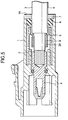
- this shield connector includes a cylindrical shield shell 2 inside a connector housing 1, and an end portion of a shielded electric wire 3 is contained at a position surrounded by the shield shell 2.
- a terminal metal 4 is fixed to the end portion of the shielded wire 3, and in addition, a conductive ring 5, a rubber plug 6 and a rubber plug holder 7 are inserted so as to cover the shielded wire 3.
- a shield layer 3A is clamped between the conductive ring 5 and an underlying ring 8 which is integrally formed with the conductive ring 5.
- Abackward end of the conductive ring 5 is connected to the shield shell 2, an electric wire insertion inlet 1A of the connector housing 1 is covered with the rubber plug 6, and the rubber plug 6 is further retained by the rubber plug holder 7 so as not to drop out.
- the rubber plug holder 7 has been provided on purpose for retaining the rubber plug 6 so as not to drop out, and therefore, components have increased in number and assembling work has been annoying.
- the present invention has been made in view of the above described circumstances, and it is an object of the invention to provide a shield connector which is excellent in assembling ability as compared with the shield connector according to the related art.
- a shield connector comprising:
- a shield connector comprising:
- the shield connector according to any one of the first and second aspects of the invention, wherein the underlying member is formed with a locking projection projecting toward the outer coating of the shielded wire.
- the underlying member has such a structure that the metal plate is curved in a U-shape, the underlying member can be attached to the shielded wire from a lateral side. Therefore, assembling ability of the underlying member increases as compared with the underlying ring, according to the related art, which has been in a cylindrical shape. Further, there will be no fear that the underlying member may move during assembling, since the underlying member has been fixed to the shielded wire by caulking.
- the underlying member is fixed to the shielded wire by caulking the first barrel portion
- the rubber plug is fixed to the underlying member by caulking the second barrel portion to the small diametered portion of the rubber plug.
- the underlying member is formed with the locking projection which projects so as to bite the outer coating of the shielded wire, the underlying member can be more reliably fixed to the shielded wire.
- Fig. 1 is a sectional side view of a shield connector according to an embodiment of the invention.
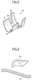
- Fig. 2 is a perspective view of an underlying member.
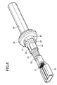
- Fig. 3 is an enlarged perspective view of a locking projection.
- Fig. 4 is a perspective view of a shielded wire with a rubber plug locked by the underlying member.
- Fig. 5 is a sectional side view of a conventional shield connector.
- a connector housing 10 provided in a shield connector in the present embodiment (hereinafter referred to simply as "a housing 10") has a containing part 11 in a cylindrical shape.
- the containing part 11 has a forward cylindrical part 12 and a backward cylindrical part 13 arranged in an axial direction. Respective one ends of the forward cylindrical part 12 and the backward cylindrical part 13 are overlapped in a radial direction and connected by connecting walls 14 at a plurality of positions in a circumferential direction.
- a shield shell 16 formed of a metal plate curved in a cylindrical shape is inserted and assembled into a gap between both the forward and the backward cylindrical parts 12, 13.
- a shielded electric wire 20, to which this shield connector is fitted has a core wire 21, an inner insulating layer 22 covering the core wire 21, a shield layer 23 braided with fine metal wires and lying outside the inner insulating layer 22, and an outer coating 24 lying at the outermost side.
- the core wire 21, the inner insulating layer 22 and the shield layer 23 are exposed from the outer coating 24 in order from its distal end.
- a terminal metal 25 is pressure fitted to the core wire 21 and inserted into the containing part 11.
- the shielded wire 20 is retained in the containing part 11 through a lock with a terminal locking mechanism (a lance 15, specifically) which is provided in a depth of the containing part 11 and the terminal metal 25.
- a rubber plug 30 Over an intermediate portion of the outer coating 24 of the shielded wire 20, is inserted a rubber plug 30.
- the rubber plug 30 is in a cylindrical shape and in tight contact with both the outer coating 24 of the shielded wire 20 and an inner face of the housing 10.
- the underlying member 40 On the outer coating 24 of the shielded wire 20, is mounted an underlying member 40. As shown in Fig. 2 in a state before the underlying member is mounted on the shielded wire 20, the underlying member 40 has a first and a second barrel portions 41, 42 formed of a metal plate curved in a U-shape, and connected by a connecting wall 42.
- the first barrel portion 41 is curved with a curvature corresponding to an outer diameter of the outer coating 24, and the second barrel portion 42 is curved with a curvature corresponding to an outer diameter of the small diametered portion 31 of the rubber plug 30.
- a locking projection 44 is formed in a bottom of the first barrel portion 41 by cutting out. As shown enlarged in Fig. 3, the locking projection 44 is constructed in such a manner that a rectilinear cut out 45 is formed in the metal plate which constitutes the first barrel portion 41 in a direction intersecting an axial direction of the shielded wire 20, and a forward side of the metal plate (a side of the cut out 45 remote from the second barrel portion 42) is stamped out to project toward the shielded wire 20.
- An electrically conductive sleeve 50 is mounted around the first barrel portion 41 as shown in Fig. 1 so as to clamp the shield layer 23 between the electrically conductive sleeve 50 and the first barrel portion 41.
- the electrically conductive sleeve 50 has a small cylindrical part 51 and a large cylindrical part 52 interconnected at their respective one ends by a disc wall 53. As shown in Fig. 1, the small cylindrical part 51 is engaged with an outer face of the first barrel portion 41 interposing the shield layer 23 therebetween, and the large cylindrical part 52 is engaged in the shield shell 16.
- the rubber plug 30 is first inserted over the shielded wire 20, and the underlying member 40 is applied to the outer coating 24 of the shielded wire 20 from a lateral side.
- the first and the second barrel portions 41, 42 are caulked by means of a tool which is not shown.
- the first barrel portion 41 is pressed to the outer coating 24, and the locking projection 44 formed in the first barrel portion 41 bites the outer coating 24, whereby the underlying member 40 is reliably fixed to the shielded wire 20 so as not to move.
- the second barrel portion 42 is fixed to the rubber plug 30 by caulking, the rubber plug 30 and the underlying member 40 are fixed to each other, and in this manner, the rubber plug 30 is made immovable with respect to the shielded wire 20.
- the electrically conductive sleeve 50 is inserted over the shielded wire 20 from the distal end, and mounted in a state that the shield layer 23 is folded back to be interposed between the small diametered portion 51 of the electrically conductive sleeve 50 and the first barrel portion 41.
- the terminal metal 25 is pressure fitted to the core wire 21 of the shielded wire 20.
- the rubber plug 30 is brought into tight contact with an inner periphery of the wire insertion inlet 18 to attain waterproofing of the wire insertion inlet 18.
- the large diametered portion 52 of the electrically conductive sleeve 50 is pushed into the shield shell 16 and brought into tight contact therewith.
- the shield layer 23 and the shield shell 16 are electrically connected to each other by way of the electrically conductive sleeve 50.
- the lance 15 comes into engagement with the terminal metal 25, and the shielded wire 20 is thus retained in the containing part 11 so as not to drop out.
- the rubber plug 30 receives a force in such a direction that it is pushed out from the wire insertion inlet 18.
- the rubber plug 30 is retained by the second barrel portion 42 of the underlying member 40 which is fixed to the shielded wire 20, and locked so as not to move in the axial direction of the shielded wire 20. Accordingly, the rubber plug 30 will not drop out from the wire insertion inlet 18.
- the rubber plug 30 is immovably fixed to the shielded wire 20 by means of the underlying member 40 and prevented from dropping out from the wire insertion inlet 18, the rubber plug holder which has been required in the shield connector according to the related art is unnecessary. Thus, the number of the components can be reduced and the assembling workability will be improved. Further, since the underlying member 40 has such a structure that the metal plate is curved in a U-shape, the underlying member 40 can be attached to the shielded wire 20 from the lateral side. Therefore, the underlying member 40 can attain better assembling ability as compared with the underlying ring according to the related art which has been simply in a cylindrical shape.
- the present invention is not limited to the embodiment as herein described referring to the above description and the drawings, but various modifications can be made within a scope of the gist of the invention.
- the underlying member 40 in the described embodiment has the second barrel portion 42 to be fixed to the rubber plug 30, the underlying member may be of such a structure that the underlying member has only the first barrel portion without providing the second barrel portion, and may not be fixed to the rubber plug.
Landscapes
- Details Of Connecting Devices For Male And Female Coupling (AREA)
- Coupling Device And Connection With Printed Circuit (AREA)
Abstract
Description
Claims (4)
- A shield connector comprising:a connector housing adapted to accommodate a distal end portion of a shielded electric wire provided with a metal terminal so as not to drop out;a shield shell adapted to cover the metal terminal;a connecting member adapted to electrically connect the shield shell to a shield layer of the shielded electric wire which is exposed from an outer coating of the shielded electric wire;a rubber plug which is fitted to an intermediate portion of the shielded electric wire to close a wire insertion inlet formed in the connector housing through which the shielded electric wire is inserted; anda underlying member formed of a metal plate curved in a U-shape, caulked and fixed to the outer coating of the shielded electric wire in a state where the outer coating is disposed inside the underlying member,wherein the shield layer is folded back over the outer coating to dispose the underlying member between the shield layer and the outer coating so as to clamp the shield layer between the underlying member and the connecting member.
- A shield connector comprising:a connector housing adapted to accommodate a distal end portion of a shielded electric wire provided with a metal terminal so as not to drop out;a shield shell adapted to cover the terminal metal;a connecting member adapted to electrically connect the shield shell to a shield layer of the shielded electric wire which is exposed from an outer coating of the shielded electric wire;a rubber plug which is fitted to an intermediate portion of the shielded electric wire to close a wire insertion inlet formed in the connector housing through which the shielded electric wire is inserted; anda underlying member having a first and second barrel portions formed of metal plate curved in a U-shape and is continuously formed along the shielded electric wire,wherein the rubber plug has a small diametered portion extending from an end face of the rubber plug toward the underlying member;the shield layer is folded back over the outer coating to dispose an underlying member between the shield layer and the outer coating so as to clamp the shield layer between the underlying member and the connecting member;the first barrel portion is caulked and fixed to the outer coating, covered with the shield layer on the outside of the first barrel, and provided with the connecting member from the outside thereof,the second barrel portion is caulked and fixed to the small diametered portion of the rubber plug.
- The shield connector according to claim 1, wherein the underlying member is formed with a locking projection projecting toward the outer coating of the shielded wire.
- The shield connector according to claim 2, wherein the underlying member is formed with a locking projection projecting toward the outer coating of the shielded wire.
Applications Claiming Priority (2)
| Application Number | Priority Date | Filing Date | Title |
|---|---|---|---|
| JP2000164113 | 2000-06-01 | ||
| JP2000164113A JP3788722B2 (en) | 2000-06-01 | 2000-06-01 | Shield connector |
Publications (3)
| Publication Number | Publication Date |
|---|---|
| EP1160933A2 true EP1160933A2 (en) | 2001-12-05 |
| EP1160933A3 EP1160933A3 (en) | 2005-03-16 |
| EP1160933B1 EP1160933B1 (en) | 2006-09-27 |
Family
ID=18667776
Family Applications (1)
| Application Number | Title | Priority Date | Filing Date |
|---|---|---|---|
| EP01112732A Expired - Lifetime EP1160933B1 (en) | 2000-06-01 | 2001-05-25 | Shield connector |
Country Status (4)
| Country | Link |
|---|---|
| US (1) | US6528727B2 (en) |
| EP (1) | EP1160933B1 (en) |
| JP (1) | JP3788722B2 (en) |
| DE (1) | DE60123325T8 (en) |
Families Citing this family (8)
| Publication number | Priority date | Publication date | Assignee | Title |
|---|---|---|---|---|
| US20050272313A1 (en) * | 2002-07-31 | 2005-12-08 | Shozo Ichikawa | Electrical connector |
| JP2004185918A (en) * | 2002-12-02 | 2004-07-02 | Sumitomo Wiring Syst Ltd | Waterproof connector |
| JP2005019319A (en) * | 2003-06-27 | 2005-01-20 | Auto Network Gijutsu Kenkyusho:Kk | Connector for equipment |
| JP4377727B2 (en) * | 2004-03-25 | 2009-12-02 | 株式会社オートネットワーク技術研究所 | Shield connector |
| US9039450B2 (en) * | 2013-01-15 | 2015-05-26 | Delphi Technologies, Inc. | Termination arrangement for a cable bundle |
| US10404048B2 (en) * | 2013-11-26 | 2019-09-03 | Commscope Technologies Llc | Adapter for sealing cover for electrical interconnections |
| FR3079077B1 (en) * | 2018-03-16 | 2020-09-18 | Raydiall | ELECTRICAL CONNECTION ASSEMBLY WITH AN ELECTRICAL CONNECTOR MOUNTED AND MOLDED ON AN ELECTRIC CABLE, ASSOCIATED REALIZATION PROCESS |
| FR3128571A1 (en) * | 2021-10-22 | 2023-04-28 | Raydiall | Pre-assembled connector sub-assembly comprising a central contact and two crimping parts of different material and/or thickness, coil of sub-assemblies and associated method of assembling a connector to a cable. |
Family Cites Families (13)
| Publication number | Priority date | Publication date | Assignee | Title |
|---|---|---|---|---|
| US1397040A (en) * | 1919-02-24 | 1921-11-15 | American Mine Door Company | Cable-splice |
| US2013217A (en) * | 1934-06-21 | 1935-09-03 | Harvey M Olmstead | Method and means for coupling electric conduits |
| US2777894A (en) * | 1956-03-05 | 1957-01-15 | Jerrold Electronics Corp | Male connector |
| US2941028A (en) * | 1956-08-10 | 1960-06-14 | Phelps Dodge Copper Prod | Solderless coaxial cable fitting |
| US3828298A (en) | 1973-01-22 | 1974-08-06 | Amp Inc | Electrical terminal for a braided shield on a coaxial cable |
| US5127843A (en) * | 1990-05-30 | 1992-07-07 | Amp Incorporated | Insulated and shielded connector |
| US5217392A (en) * | 1992-11-13 | 1993-06-08 | The Whitaker Corporation | Coaxial cable-to-cable splice connector |
| SE505224C2 (en) * | 1993-12-07 | 1997-07-21 | Ericsson Telefon Ab L M | Connectors, especially designed to connect a coaxial cable to a connector |
| JP3097816B2 (en) * | 1995-03-10 | 2000-10-10 | 矢崎総業株式会社 | Sheath displacement prevention structure of shielded wire |
| JP3419638B2 (en) * | 1996-11-12 | 2003-06-23 | 住友電装株式会社 | Shield connector |
| US5965847A (en) | 1996-11-12 | 1999-10-12 | Sumitomo Wiring Systems, Ltd. | Shield connector |
| GB2329283A (en) * | 1997-09-12 | 1999-03-17 | Itt Mfg Enterprises Inc | Screened cable terminating ferrule |
| US6270377B1 (en) | 1998-07-16 | 2001-08-07 | Harness System Technologies Research, Ltd. | Shielding connector |
-
2000
- 2000-06-01 JP JP2000164113A patent/JP3788722B2/en not_active Expired - Fee Related
-
2001
- 2001-04-23 US US09/839,145 patent/US6528727B2/en not_active Expired - Fee Related
- 2001-05-25 EP EP01112732A patent/EP1160933B1/en not_active Expired - Lifetime
- 2001-05-25 DE DE60123325T patent/DE60123325T8/en not_active Expired - Fee Related
Also Published As
| Publication number | Publication date |
|---|---|
| EP1160933B1 (en) | 2006-09-27 |
| EP1160933A3 (en) | 2005-03-16 |
| DE60123325D1 (en) | 2006-11-09 |
| DE60123325T2 (en) | 2007-04-05 |
| US6528727B2 (en) | 2003-03-04 |
| JP3788722B2 (en) | 2006-06-21 |
| DE60123325T8 (en) | 2007-08-16 |
| US20010047877A1 (en) | 2001-12-06 |
| JP2001345154A (en) | 2001-12-14 |
Similar Documents
| Publication | Publication Date | Title |
|---|---|---|
| CN111697384B (en) | Connector and method for assembling connector | |
| US7927136B2 (en) | Connector with shielding connecting portion and press-crimping member | |
| EP1098397B1 (en) | Equipment direct-mounting type shield electric connector assembly | |
| JP3097816B2 (en) | Sheath displacement prevention structure of shielded wire | |
| JPH06203919A (en) | Shielding connector | |
| JP3262501B2 (en) | Termination structure of shielded wires | |
| EP1160933B1 (en) | Shield connector | |
| US11374350B2 (en) | Waterproof communication cable | |
| JP2000286016A (en) | Shield connector | |
| JP2008181810A (en) | Shield terminal | |
| JP3074441B2 (en) | Contact movement prevention structure | |
| JPH11354218A (en) | Shield connector | |
| JPH10144405A (en) | Shield connector | |
| JP2005174813A (en) | connector | |
| JP3595132B2 (en) | Shield structure of shield connector directly attached to equipment | |
| JP2004158376A (en) | Shielded connector | |
| JP3174236B2 (en) | Braided connection structure of shielded connector | |
| JP6195137B1 (en) | connector | |
| JP3362842B2 (en) | Shield connector | |
| JP4392381B2 (en) | Shield connector | |
| JP2001326034A (en) | Electrical connector with shield function | |
| JP3375280B2 (en) | Shield connector | |
| JPH11262151A (en) | Termination structure of shielded wires | |
| JP3283468B2 (en) | Shield connector | |
| JP2000268919A (en) | Shield connector |
Legal Events
| Date | Code | Title | Description |
|---|---|---|---|
| PUAI | Public reference made under article 153(3) epc to a published international application that has entered the european phase |
Free format text: ORIGINAL CODE: 0009012 |
|
| AK | Designated contracting states |
Kind code of ref document: A2 Designated state(s): AT BE CH CY DE DK ES FI FR GB GR IE IT LI LU MC NL PT SE TR |
|
| AX | Request for extension of the european patent |
Free format text: AL;LT;LV;MK;RO;SI |
|
| PUAL | Search report despatched |
Free format text: ORIGINAL CODE: 0009013 |
|
| AK | Designated contracting states |
Kind code of ref document: A3 Designated state(s): AT BE CH CY DE DK ES FI FR GB GR IE IT LI LU MC NL PT SE TR |
|
| AX | Request for extension of the european patent |
Extension state: AL LT LV MK RO SI |
|
| RIC1 | Information provided on ipc code assigned before grant |
Ipc: 7H 01R 9/05 B Ipc: 7H 01R 13/658 A Ipc: 7H 01R 13/52 B |
|
| 17P | Request for examination filed |
Effective date: 20050602 |
|
| AKX | Designation fees paid |
Designated state(s): DE FR |
|
| GRAP | Despatch of communication of intention to grant a patent |
Free format text: ORIGINAL CODE: EPIDOSNIGR1 |
|
| GRAS | Grant fee paid |
Free format text: ORIGINAL CODE: EPIDOSNIGR3 |
|
| GRAA | (expected) grant |
Free format text: ORIGINAL CODE: 0009210 |
|
| RIN1 | Information on inventor provided before grant (corrected) |
Inventor name: MIYAZAKI, SHO,C/O AUTONETWORKS TECHNOLOGIES, LTD. |
|
| AK | Designated contracting states |
Kind code of ref document: B1 Designated state(s): DE FR |
|
| REF | Corresponds to: |
Ref document number: 60123325 Country of ref document: DE Date of ref document: 20061109 Kind code of ref document: P |
|
| ET | Fr: translation filed | ||
| PLBE | No opposition filed within time limit |
Free format text: ORIGINAL CODE: 0009261 |
|
| STAA | Information on the status of an ep patent application or granted ep patent |
Free format text: STATUS: NO OPPOSITION FILED WITHIN TIME LIMIT |
|
| 26N | No opposition filed |
Effective date: 20070628 |
|
| PGFP | Annual fee paid to national office [announced via postgrant information from national office to epo] |
Ref country code: DE Payment date: 20090527 Year of fee payment: 9 Ref country code: FR Payment date: 20090515 Year of fee payment: 9 |
|
| REG | Reference to a national code |
Ref country code: FR Ref legal event code: ST Effective date: 20110131 |
|
| PG25 | Lapsed in a contracting state [announced via postgrant information from national office to epo] |
Ref country code: DE Free format text: LAPSE BECAUSE OF NON-PAYMENT OF DUE FEES Effective date: 20101201 |
|
| PG25 | Lapsed in a contracting state [announced via postgrant information from national office to epo] |
Ref country code: FR Free format text: LAPSE BECAUSE OF NON-PAYMENT OF DUE FEES Effective date: 20100531 |