EP1160798A1 - Spacer spring force adjustment tool and method of adjusting the spacer spring force - Google Patents
Spacer spring force adjustment tool and method of adjusting the spacer spring force Download PDFInfo
- Publication number
- EP1160798A1 EP1160798A1 EP01304615A EP01304615A EP1160798A1 EP 1160798 A1 EP1160798 A1 EP 1160798A1 EP 01304615 A EP01304615 A EP 01304615A EP 01304615 A EP01304615 A EP 01304615A EP 1160798 A1 EP1160798 A1 EP 1160798A1
- Authority
- EP
- European Patent Office
- Prior art keywords
- spring
- arm
- spacer
- probe
- micrometer
- Prior art date
- Legal status (The legal status is an assumption and is not a legal conclusion. Google has not performed a legal analysis and makes no representation as to the accuracy of the status listed.)
- Withdrawn
Links
- 125000006850 spacer group Chemical group 0.000 title claims abstract description 70
- 238000000034 method Methods 0.000 title claims description 7
- 239000000523 sample Substances 0.000 claims abstract description 35
- 239000003758 nuclear fuel Substances 0.000 claims description 11
- 238000003780 insertion Methods 0.000 claims description 5
- 230000037431 insertion Effects 0.000 claims description 5
- 230000004044 response Effects 0.000 claims description 3
- 230000003247 decreasing effect Effects 0.000 abstract 1
- 239000000446 fuel Substances 0.000 description 8
- 230000036316 preload Effects 0.000 description 6
- 238000006073 displacement reaction Methods 0.000 description 3
- 238000004519 manufacturing process Methods 0.000 description 3
- 230000000712 assembly Effects 0.000 description 2
- 238000000429 assembly Methods 0.000 description 2
- 239000000463 material Substances 0.000 description 2
- 230000009467 reduction Effects 0.000 description 2
- 230000009471 action Effects 0.000 description 1
- 238000005452 bending Methods 0.000 description 1
- 230000008859 change Effects 0.000 description 1
- 230000000694 effects Effects 0.000 description 1
- 238000005259 measurement Methods 0.000 description 1
- 230000007246 mechanism Effects 0.000 description 1
Images

Classifications
-
- G—PHYSICS
- G21—NUCLEAR PHYSICS; NUCLEAR ENGINEERING
- G21C—NUCLEAR REACTORS
- G21C3/00—Reactor fuel elements and their assemblies; Selection of substances for use as reactor fuel elements
- G21C3/30—Assemblies of a number of fuel elements in the form of a rigid unit
- G21C3/32—Bundles of parallel pin-, rod-, or tube-shaped fuel elements
- G21C3/34—Spacer grids
- G21C3/356—Spacer grids being provided with fuel element supporting members
-
- G—PHYSICS
- G21—NUCLEAR PHYSICS; NUCLEAR ENGINEERING
- G21C—NUCLEAR REACTORS
- G21C3/00—Reactor fuel elements and their assemblies; Selection of substances for use as reactor fuel elements
- G21C3/30—Assemblies of a number of fuel elements in the form of a rigid unit
- G21C3/32—Bundles of parallel pin-, rod-, or tube-shaped fuel elements
- G21C3/34—Spacer grids
- G21C3/3424—Fabrication of spacer grids
-
- Y—GENERAL TAGGING OF NEW TECHNOLOGICAL DEVELOPMENTS; GENERAL TAGGING OF CROSS-SECTIONAL TECHNOLOGIES SPANNING OVER SEVERAL SECTIONS OF THE IPC; TECHNICAL SUBJECTS COVERED BY FORMER USPC CROSS-REFERENCE ART COLLECTIONS [XRACs] AND DIGESTS
- Y02—TECHNOLOGIES OR APPLICATIONS FOR MITIGATION OR ADAPTATION AGAINST CLIMATE CHANGE
- Y02E—REDUCTION OF GREENHOUSE GAS [GHG] EMISSIONS, RELATED TO ENERGY GENERATION, TRANSMISSION OR DISTRIBUTION
- Y02E30/00—Energy generation of nuclear origin
- Y02E30/30—Nuclear fission reactors
Definitions
- the present invention generally relates to spacers for a nuclear fuel bundle and particularly relates to an adjustment tool and method of using the tool for adjusting the spring force of the spacer springs.
- Nuclear fuel rod spacers for nuclear fuel rod assemblies are typically designed with spring mechanisms in the spacers that exert preload forces normal to each fuel rod in each fuel rod cell of the spacer.
- preload forces is meant the forces applied in initially manufactured spacers before irradiation or other activities that would potentially stress the springs and result in a reduction of the spring forces.
- these preload forces are specified in the range of about one to three pounds for each spacer cell.
- a spring force outside of the specified range is grounds for rejection of the entire spacer.
- a known device for example, see U.S. Patent No. 5,215,705, can measure the spring force of the spacer spring.
- the device disclosed in that patent does not adjust the spring force of the spacer spring. Accordingly, there is a need for a tool for adjusting the spring force of spacer springs after initial manufacture of the spacer should the spring preload forces lie outside a predetermined range of preload forces.
- a pair of adjustment tools for making calibrated adjustments in the spacer spring dimensions thereby to alter the spring forces in fabricated spacer assemblies. It is necessary to make adjustment to the spring forces in fabricated spacers in a manner that can be both calibrated and will not result in unacceptable damage to the spacers.
- Such tools must also meet standard requirements for nuclear fuel manufacturing including fabrication of the tools from nuclear grade materials and tools which will not damage the spacers or springs during insertion or removal nor contaminate the spacer with foreign materials or debris.
- Two distinct tools are provided for respectively displacing the spacer spring in an outward or an inward direction, depending upon the measured spring force.
- the tool For displacing the spring in an outward direction to adjust the spring force, the tool includes a holder having a head, a probe depending from the head for insertion into the spacer opening and a lever pivoted to the holder.
- a micrometer is preferably secured to the head and has a displaceable drive head for engaging one end of the pivoted arm. By displacing the one end of the pivoted arm, the opposite end engages the spring and displaces the spring outwardly relative to the probe and spacer opening to adjust, i.e., decrease, the spring force.
- the second tool includes a holder having a probe, a depending pivotal arm laterally outwardly of the probe and a micrometer attached to the head.
- the probe and pivotal arm are located in the spacer to straddle the spring.
- the change in spring force is established by calibrating the micrometer setting against a resulting spring force for springs in test or calibration spacers, e.g., as measured by a spring force measurement tool such as described in the aforementioned U.S. Patent No. 5,215,705.
- a spring force measurement tool such as described in the aforementioned U.S. Patent No. 5,215,705.
- the deformation constant is determined from empirical data collected by measuring the spring force before and after bending the spring with the tool hereof to various recorded set points. Once this constant has been determined the amount of deflection needed to alter the spring force to any given value can be readily determined using this equation.
- apparatus for adjusting the spring force of springs of a spacer for a nuclear fuel bundle comprising a tool including a tool holder probe for insertion into the opening of a spacer and a movable drive head and an arm carried by the tool and pivoted intermediate opposite ends thereof, the arm extending generally parallel to the probe and having a drive head engaging surface for pivoting the arm in response to movement of the tool drive head and a spacer spring engaging surface adjacent an opposite end thereof for displacing the spring thereby adjusting the spring force of the spring.
- a method of adjusting the spring force of a spring in a spacer cell opening of a spacer for a nuclear fuel bundle comprising the steps of providing a holder having a probe and a displaceable arm, inserting the probe into the spacer opening and displacing the arm to displace the spring to thereby adjust the spring force of the spacer spring.
- FIG. 1 there is illustrated a form of an adjustment tool, generally designated 10, for adjusting the spring force of a spacer spring 12 by displacing the spring in an outward direction relative to the spacer opening in which the spring resides and in which opening a nuclear fuel rod, not shown, is located in use.
- the tool 10 includes a tool holder 14 having a tool head 16 and a probe 18.
- the holder 14 also includes a bracket 20 to which a micrometer 22 is secured.
- the holder head 16 includes a lateral through opening 24 for receiving a head of micrometer 22 and an opening 26 normal thereto.
- the bracket 20 is a right angle bracket having a circular opening 28 in registration with opening 26.
- the probe 18 is received through the circular opening 28.
- the holder head 16 is secured to the bracket 14 by screws 30.
- the end of the micrometer 22 includes a displaceable drive head 32 which is displaceable in and out relative to the micrometer in response to rotary movement of the micrometer handle 34.
- Probe 18 has a cross-sectional configuration sized for reception within a spacer cell opening.
- a representative spacer cell 36 is illustrated in Figure 2. It will be appreciated that the spacer cell comprises one of a plurality of spacer cells formed in a rectilinear array thereof, for example, a 9x9 or 10x10 array of cells for receiving nuclear fuel rods and forms part of a nuclear fuel bundle, not shown.
- a representative spacer disclosing an example of a typical spacer cell for use with the tool of the present invention is described and illustrated in U.S. Patent No. 5,186,891.
- Each cell 36 comprises upper and lower bands, only the lower band 37 being illustrated, each band having a pair of stops 38 at right angularly related sides and a pair of inwardly directed springs 40 on opposite sides of the cell from the stops.
- Each spring 40 extends between the upper and lower bands, projects inwardly of the bands and has an intermediate dimple 42 for engagement with the fuel rod extending through the spacer cell.
- the probe 18 is sized to engage the stops 38 and dimples 42 of the springs 40.
- an arm 44 is pivotally mounted to the tool holder 14 for pivotal movement about an axis 46.
- the proximal or upper end of the arm 44 has a micrometer drive head engaging surface 48 for engagement with the micrometer head 32.
- the distal end of the arm 44 includes a spring engaging surface 50 ( Figure 1).
- the probe 18 is inserted into the cell 36 to engage the spring stops 38 and springs 40. It will be appreciated that the probe 18 and arm 44 are dimensioned such that, upon insertion, the spring engaging surface 50 of arm 44 lies at an elevation for engagement with the dimple 42 of the spring 40.
- the micrometer 22 is previously calibrated to a micrometer setting which will obtain a desired spring force for the spring within the predetermined range of spring forces corresponding to the preload forces. After the probe 18 has been inserted and the surface 50 of arm 44 is aligned with the dimple 42 of the spring whose spring force is to be adjusted, the micrometer is set to the predetermined setting. This causes the micrometer drive head 32 to engage the drive head engaging surface 48 of arm 44, pivoting arm 44 about axis 46.
- the tool is configured to adjust, i.e., increase the spring force by adjusting or displacing the spring in a direction toward the spacer opening which receives the fuel rod.
- the tool 60 includes a tool holder 61, probe 62, a tool head 64, a lateral opening 65, a micrometer 66 secured to the tool head 64, the micrometer having a micrometer drive head 68 extending through opening 65.
- An arm 70 is pivoted about a pin 72 secured to head 64, the proximal or upper end 74 of the arm being disposed between a spring 76 and the micrometer drive head 68 and having a drive head engaging surface 77.
- the lower or distal end 80 of the arm 70 carries a drive head comprised of a pivotal element 82 for pivotal movement about an axis 84.
- the pivotal element 82 is located relative to the head a distance such that the opposite ends of element 82, i.e., spring-engaging or contact surfaces 86, straddle the dimple 42 on the spring 40.
- the probe 62 also includes an elongated slot 88 extending its length lying opposite arm 70. Slot 88 has a width sufficient to receive the spring 40.
- the probe 62 is inserted into the spacer cell opening 36 with the arm 80 and element 82 extending along the outside of the spacer cell. That is, the probe 62 and the arm 80 and element 82 straddle the spring 40.
- the pivotal element has opposite ends which straddle the dimple 42.
- rotation of the micrometer handle 67 to the predetermined setting displaces the drive head 68 forwardly to pivot the arm 70, causing the element 82 to displace the spring 40 in a direction inwardly of the cell into spring slot 88. This displacement increases the spring force of the spring 40 on the fuel rod when the spacer is in assembly with the fuel bundle.
- the micrometer setting is returned to its original setting and the tool 60 is withdrawn from the spacer cell.
- the adjoining spring may likewise be adjusted as necessary or desirable. It will also be appreciated that one of the springs of the spacer cells may require an increase in spring force, while the adjacent spring may require a decrease in spring force. Thus, both tools may be used in a particular spacer cell.
Landscapes
- Physics & Mathematics (AREA)
- Engineering & Computer Science (AREA)
- Plasma & Fusion (AREA)
- General Engineering & Computer Science (AREA)
- High Energy & Nuclear Physics (AREA)
- Fuel Cell (AREA)
- Monitoring And Testing Of Nuclear Reactors (AREA)
Abstract
Description
- The present invention generally relates to spacers for a nuclear fuel bundle and particularly relates to an adjustment tool and method of using the tool for adjusting the spring force of the spacer springs.
- Nuclear fuel rod spacers for nuclear fuel rod assemblies are typically designed with spring mechanisms in the spacers that exert preload forces normal to each fuel rod in each fuel rod cell of the spacer. By preload forces is meant the forces applied in initially manufactured spacers before irradiation or other activities that would potentially stress the springs and result in a reduction of the spring forces. Typically, these preload forces are specified in the range of about one to three pounds for each spacer cell. A spring force outside of the specified range is grounds for rejection of the entire spacer. A known device, for example, see U.S. Patent No. 5,215,705, can measure the spring force of the spacer spring. However, the device disclosed in that patent does not adjust the spring force of the spacer spring. Accordingly, there is a need for a tool for adjusting the spring force of spacer springs after initial manufacture of the spacer should the spring preload forces lie outside a predetermined range of preload forces.
- In accordance with a preferred embodiment of the present invention, there are provided a pair of adjustment tools for making calibrated adjustments in the spacer spring dimensions thereby to alter the spring forces in fabricated spacer assemblies. It is necessary to make adjustment to the spring forces in fabricated spacers in a manner that can be both calibrated and will not result in unacceptable damage to the spacers. Such tools must also meet standard requirements for nuclear fuel manufacturing including fabrication of the tools from nuclear grade materials and tools which will not damage the spacers or springs during insertion or removal nor contaminate the spacer with foreign materials or debris. Two distinct tools are provided for respectively displacing the spacer spring in an outward or an inward direction, depending upon the measured spring force. For displacing the spring in an outward direction to adjust the spring force, the tool includes a holder having a head, a probe depending from the head for insertion into the spacer opening and a lever pivoted to the holder. A micrometer is preferably secured to the head and has a displaceable drive head for engaging one end of the pivoted arm. By displacing the one end of the pivoted arm, the opposite end engages the spring and displaces the spring outwardly relative to the probe and spacer opening to adjust, i.e., decrease, the spring force.
- Where the spring requires displacement inwardly toward the opening, the second tool includes a holder having a probe, a depending pivotal arm laterally outwardly of the probe and a micrometer attached to the head. The probe and pivotal arm are located in the spacer to straddle the spring. By displacing the drive head of the micrometer in engagement with one end of the pivoted arm, the opposite end of the pivoted arm engages the spring to displace the spring inwardly toward the probe thereby adjusting, i.e., increasing the spring force of the spacer spring in the cell receiving the probe. In both tools, the change in spring force is established by calibrating the micrometer setting against a resulting spring force for springs in test or calibration spacers, e.g., as measured by a spring force measurement tool such as described in the aforementioned U.S. Patent No. 5,215,705. There is a linear relationship where the deformation constant is determined from empirical data collected by measuring the spring force before and after bending the spring with the tool hereof to various recorded set points. Once this constant has been determined the amount of deflection needed to alter the spring force to any given value can be readily determined using this equation. The deformation constant is given by the equation: Δ Spring Force = (Deformation Constant) (Δ Spring Deflection).
- In a preferred embodiment according to the present invention, there is provided apparatus for adjusting the spring force of springs of a spacer for a nuclear fuel bundle, comprising a tool including a tool holder probe for insertion into the opening of a spacer and a movable drive head and an arm carried by the tool and pivoted intermediate opposite ends thereof, the arm extending generally parallel to the probe and having a drive head engaging surface for pivoting the arm in response to movement of the tool drive head and a spacer spring engaging surface adjacent an opposite end thereof for displacing the spring thereby adjusting the spring force of the spring.
- In a further preferred embodiment according to the present invention, there is provided a method of adjusting the spring force of a spring in a spacer cell opening of a spacer for a nuclear fuel bundle, comprising the steps of providing a holder having a probe and a displaceable arm, inserting the probe into the spacer opening and displacing the arm to displace the spring to thereby adjust the spring force of the spacer spring.
- Embodiments of the invention will now be described, by way of example, with reference to the accompanying drawings, in which:
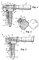
- FIGURE 1 is a side elevational view of an adjustment tool according to the present invention with a portion of the spacer spring being illustrated;
- FIGURE 2 is a cross-sectional view thereof taken generally about on line 2-2 in Figure 1 and illustrating the tool disposed in a spacer opening;
- FIGURE 3 is a view similar to Figure 1 illustrating adjustment of the spring force of the spring by the tool;
- FIGURE 4 is a cross-sectional view of a further form of adjustment tool hereof;
- FIGURE 5 is a cross-sectional view thereof taken generally about on line 5-5 in Figure 4 and illustrating portions of the tool disposed on opposite sides of a spacer spring; and
- FIGURE 6 is a view similar to Figure 4 illustrating the displacement of the spring in a direction inwardly of the spacer opening.
-
- Referring now to Figure 1, there is illustrated a form of an adjustment tool, generally designated 10, for adjusting the spring force of a
spacer spring 12 by displacing the spring in an outward direction relative to the spacer opening in which the spring resides and in which opening a nuclear fuel rod, not shown, is located in use. Thetool 10 includes atool holder 14 having atool head 16 and aprobe 18. Theholder 14 also includes abracket 20 to which amicrometer 22 is secured. - The
holder head 16 includes a lateral through opening 24 for receiving a head ofmicrometer 22 and an opening 26 normal thereto. Thebracket 20 is a right angle bracket having acircular opening 28 in registration with opening 26. Theprobe 18 is received through thecircular opening 28. Theholder head 16 is secured to thebracket 14 byscrews 30. As illustrated in Figure 3, the end of themicrometer 22 includes adisplaceable drive head 32 which is displaceable in and out relative to the micrometer in response to rotary movement of themicrometer handle 34. -
Probe 18 has a cross-sectional configuration sized for reception within a spacer cell opening. Arepresentative spacer cell 36 is illustrated in Figure 2. It will be appreciated that the spacer cell comprises one of a plurality of spacer cells formed in a rectilinear array thereof, for example, a 9x9 or 10x10 array of cells for receiving nuclear fuel rods and forms part of a nuclear fuel bundle, not shown. A representative spacer disclosing an example of a typical spacer cell for use with the tool of the present invention is described and illustrated in U.S. Patent No. 5,186,891. Eachcell 36 comprises upper and lower bands, only thelower band 37 being illustrated, each band having a pair ofstops 38 at right angularly related sides and a pair of inwardly directedsprings 40 on opposite sides of the cell from the stops. Eachspring 40 extends between the upper and lower bands, projects inwardly of the bands and has anintermediate dimple 42 for engagement with the fuel rod extending through the spacer cell. As illustrated in Figure 2, theprobe 18 is sized to engage thestops 38 and dimples 42 of thesprings 40. - Referring back to Figure 3, an
arm 44 is pivotally mounted to thetool holder 14 for pivotal movement about anaxis 46. The proximal or upper end of thearm 44 has a micrometer drivehead engaging surface 48 for engagement with themicrometer head 32. On the opposite side ofarm 44 fromsurface 48 there is provided aspring 49, the force of which is adjustable by a sockethead cap screw 51. The distal end of thearm 44 includes a spring engaging surface 50 (Figure 1). - To use
tool 10, theprobe 18 is inserted into thecell 36 to engage thespring stops 38 andsprings 40. It will be appreciated that theprobe 18 andarm 44 are dimensioned such that, upon insertion, the springengaging surface 50 ofarm 44 lies at an elevation for engagement with the dimple 42 of thespring 40. Themicrometer 22 is previously calibrated to a micrometer setting which will obtain a desired spring force for the spring within the predetermined range of spring forces corresponding to the preload forces. After theprobe 18 has been inserted and thesurface 50 ofarm 44 is aligned with the dimple 42 of the spring whose spring force is to be adjusted, the micrometer is set to the predetermined setting. This causes themicrometer drive head 32 to engage the drivehead engaging surface 48 ofarm 44, pivotingarm 44 aboutaxis 46. This pivoting action, as illustrated in Figure 3, causes the spacer springengaging surface 50 to displace the spring in a direction outwardly of thespacer cell 36 thereby adjusting the spring force. Once the spring force has been adjusted, the micrometer is set back to an original setting and the tool is withdrawn for use in adjusting the second spring in the spacer cell as necessary or desirable.Spring 49 biases the upper end of thearm 44 into following engagement with the micrometer head. Screw 51 also limits the range of travel ofarm 44 to prevent damage tospring 12. It will be appreciated that the foregoing causes a reduction in the force ofspring 40 thereby lowering the force of thespring 40 on a fuel rod received on the cell when the fuel bundle is assembled. - Referring now to the embodiment hereof illustrated in Figures 4-6, a similar tool, generally designated 60, is provided. In this embodiment, however, the tool is configured to adjust, i.e., increase the spring force by adjusting or displacing the spring in a direction toward the spacer opening which receives the fuel rod. To accomplish this, the
tool 60 includes atool holder 61,probe 62, atool head 64, alateral opening 65, amicrometer 66 secured to thetool head 64, the micrometer having amicrometer drive head 68 extending throughopening 65. Anarm 70 is pivoted about apin 72 secured to head 64, the proximal orupper end 74 of the arm being disposed between aspring 76 and themicrometer drive head 68 and having a drivehead engaging surface 77. The lower ordistal end 80 of thearm 70 carries a drive head comprised of apivotal element 82 for pivotal movement about anaxis 84. Thepivotal element 82 is located relative to the head a distance such that the opposite ends ofelement 82, i.e., spring-engaging or contact surfaces 86, straddle thedimple 42 on thespring 40. Theprobe 62 also includes anelongated slot 88 extending its length lying oppositearm 70.Slot 88 has a width sufficient to receive thespring 40. - To use the
tool 60 illustrated in Figures 4-6, theprobe 62 is inserted into the spacer cell opening 36 with thearm 80 andelement 82 extending along the outside of the spacer cell. That is, theprobe 62 and thearm 80 andelement 82 straddle thespring 40. When the prove is fully inserted, the pivotal element has opposite ends which straddle thedimple 42. As illustrated in Figure 6, rotation of the micrometer handle 67 to the predetermined setting displaces thedrive head 68 forwardly to pivot thearm 70, causing theelement 82 to displace thespring 40 in a direction inwardly of the cell intospring slot 88. This displacement increases the spring force of thespring 40 on the fuel rod when the spacer is in assembly with the fuel bundle. After the spring force has been adjusted, the micrometer setting is returned to its original setting and thetool 60 is withdrawn from the spacer cell. The adjoining spring may likewise be adjusted as necessary or desirable. It will also be appreciated that one of the springs of the spacer cells may require an increase in spring force, while the adjacent spring may require a decrease in spring force. Thus, both tools may be used in a particular spacer cell.
Claims (10)
- Apparatus for adjusting the spring force of springs (40) of a spacer for a nuclear fuel bundle, comprising:a tool (10, 60) including a tool holder (14, 61), a probe (18, 62) for insertion into the opening of a spacer and a movable drive head (32, 68); andan arm (44, 70) carried by said tool and pivoted intermediate opposite ends thereof, said arm extending generally parallel to said probe and having a drive head engaging surface (48, 77) for pivoting said arm in response to movement of the tool drive head and a spacer spring engaging surface (50, 86) adjacent an opposite end thereof for displacing the spring thereby adjusting the spring force of the spring.
- Apparatus according to Claim 1 wherein said tool comprises a micrometer (22, 66) having a setting for establishing a predetermined resulting spring force for the spacer spring.
- Apparatus according to Claim 1 wherein said spacer spring engaging surface (86) of said arm comprises an element pivoted on said opposite end of said arm and having a pair of spring contact surfaces (86).
- Apparatus according to Claim 1 wherein said arm (44, 70) is pivotally carried by said probe.
- Apparatus according to Claim 1 wherein said holder (61) includes a head (64), said probe (62) projecting from said holder head, said arm (70) being pivotally carried by said head (64).
- Apparatus according to Claim 1 wherein said holder (14, 61) includes a head (16, 64) mounted adjacent a proximal end of said probe (18, 62) and having an opening (26), said tool including a micrometer (22, 66) carried by said head (16, 64) with said drive head (32, 68) extending into said opening, said holder head (16, 64) including a second opening for receiving a portion of said arm (44, 70) and enabling registration of said drive head (32, 68) and said drive head (46, 77) engaging surface within said holder head.
- A method of adjusting the spring force of a spring (40) in a spacer cell opening of a spacer for a nuclear fuel bundle, comprising the steps of:providing a holder (14, 61) having a probe (18, 62) and a displaceable arm (44, 70);inserting the probe into the spacer opening; anddisplacing the arm to displace the spring to thereby adjust the spring force of the spacer spring.
- A method according to Claim 7 wherein a micrometer (22, 66) is secured to the holder (14, 61) and including the step of displacing the arm a predetermined distance in accordance with a predetermined setting on the micrometer to provide a predetermined spring force to the spring.
- A method according to Claim 7 wherein a micrometer (22) is secured to the holder (14) and including the steps of displacing the arm (44) a predetermined distance in accordance with a predetermined setting on the micrometer to provide a predetermined spring force to the spring and displacing the arm such that a spring engaging portion (50) thereof is displaced outwardly away from said probe.
- A method according to Claim 7 wherein a micrometer (66) is secured to the holder (61) and including the steps of displacing the arm (70) a predetermined distance in accordance with a predetermined setting on the micrometer to provide a predetermined spring force to the spring and displacing the arm such that a spring engaging surface (86) thereof is displaced inwardly toward the probe.
Applications Claiming Priority (2)
| Application Number | Priority Date | Filing Date | Title |
|---|---|---|---|
| US580490 | 1984-02-15 | ||
| US09/580,490 US6385269B1 (en) | 2000-05-30 | 2000-05-30 | Spacer spring force adjustment tool and method of adjusting the spacer spring force |
Publications (1)
| Publication Number | Publication Date |
|---|---|
| EP1160798A1 true EP1160798A1 (en) | 2001-12-05 |
Family
ID=24321314
Family Applications (1)
| Application Number | Title | Priority Date | Filing Date |
|---|---|---|---|
| EP01304615A Withdrawn EP1160798A1 (en) | 2000-05-30 | 2001-05-24 | Spacer spring force adjustment tool and method of adjusting the spacer spring force |
Country Status (3)
| Country | Link |
|---|---|
| US (1) | US6385269B1 (en) |
| EP (1) | EP1160798A1 (en) |
| JP (1) | JP2002090493A (en) |
Cited By (1)
| Publication number | Priority date | Publication date | Assignee | Title |
|---|---|---|---|---|
| TWI401134B (en) * | 2010-01-26 | 2013-07-11 | Macronix Int Co Ltd | Adjusting fixtures and applying correction methods |
Families Citing this family (2)
| Publication number | Priority date | Publication date | Assignee | Title |
|---|---|---|---|---|
| JP6183484B2 (en) * | 2015-07-31 | 2017-08-23 | 有限会社円研工業 | Internal angle measuring tool |
| US10438709B2 (en) * | 2015-12-31 | 2019-10-08 | Westinghouse Electric Company Llc | Measurement apparatus for determining compressive loading that will be applied to a fuel rod of a pressurized water reactor |
Citations (6)
| Publication number | Priority date | Publication date | Assignee | Title |
|---|---|---|---|---|
| US4427622A (en) * | 1980-09-04 | 1984-01-24 | Kraftwerk Union Aktiengesellschaft | Alignment tool for spacers of nuclear reactor fuel assemblies |
| US4652421A (en) * | 1985-09-05 | 1987-03-24 | Westinghouse Electric Corp. | Outer grid strap protruding spring repair apparatus |
| US4668466A (en) * | 1985-02-19 | 1987-05-26 | Westinghouse Electric Corp. | Grid cell spring force measurement apparatus and method |
| US5215705A (en) * | 1991-02-25 | 1993-06-01 | General Electric Company | Nuclear fuel bundle spacer spring force gauge |
| US5343504A (en) * | 1993-02-25 | 1994-08-30 | General Electric Company | Nuclear fuel bundle spacer spring constant gauge |
| US5490418A (en) * | 1993-11-12 | 1996-02-13 | Societe Franco-Belge De Fabrication De Combustibles | Device for measuring the force exerted by a grid spring |
Family Cites Families (1)
| Publication number | Priority date | Publication date | Assignee | Title |
|---|---|---|---|---|
| US5186891A (en) * | 1991-05-17 | 1993-02-16 | General Electric Company | Swirl vanes in inconel spacer |
-
2000
- 2000-05-30 US US09/580,490 patent/US6385269B1/en not_active Expired - Fee Related
-
2001
- 2001-05-24 EP EP01304615A patent/EP1160798A1/en not_active Withdrawn
- 2001-05-29 JP JP2001159775A patent/JP2002090493A/en not_active Withdrawn
Patent Citations (6)
| Publication number | Priority date | Publication date | Assignee | Title |
|---|---|---|---|---|
| US4427622A (en) * | 1980-09-04 | 1984-01-24 | Kraftwerk Union Aktiengesellschaft | Alignment tool for spacers of nuclear reactor fuel assemblies |
| US4668466A (en) * | 1985-02-19 | 1987-05-26 | Westinghouse Electric Corp. | Grid cell spring force measurement apparatus and method |
| US4652421A (en) * | 1985-09-05 | 1987-03-24 | Westinghouse Electric Corp. | Outer grid strap protruding spring repair apparatus |
| US5215705A (en) * | 1991-02-25 | 1993-06-01 | General Electric Company | Nuclear fuel bundle spacer spring force gauge |
| US5343504A (en) * | 1993-02-25 | 1994-08-30 | General Electric Company | Nuclear fuel bundle spacer spring constant gauge |
| US5490418A (en) * | 1993-11-12 | 1996-02-13 | Societe Franco-Belge De Fabrication De Combustibles | Device for measuring the force exerted by a grid spring |
Cited By (1)
| Publication number | Priority date | Publication date | Assignee | Title |
|---|---|---|---|---|
| TWI401134B (en) * | 2010-01-26 | 2013-07-11 | Macronix Int Co Ltd | Adjusting fixtures and applying correction methods |
Also Published As
| Publication number | Publication date |
|---|---|
| JP2002090493A (en) | 2002-03-27 |
| US6385269B1 (en) | 2002-05-07 |
Similar Documents
| Publication | Publication Date | Title |
|---|---|---|
| DE10102171B4 (en) | Longitudinal Linearity Compensation Method and Rotational Accuracy Compensation Method of a Meter | |
| DE102004015668B3 (en) | Apparatus for quick temperature measurement of a work piece on coordinate measurement apparatus with a measuring probe head and using a temperature sensor | |
| EP2249120A2 (en) | Tensioning device, holding device and storage device | |
| EP2096424A2 (en) | Actuating device for testing torque transmission keys | |
| EP0123895A1 (en) | Measuring apparatus | |
| EP0327669A2 (en) | Dial bore gage | |
| US6385269B1 (en) | Spacer spring force adjustment tool and method of adjusting the spacer spring force | |
| DE20220754U1 (en) | Fiber optic wafer probe for measuring the parameters of photodetectors and other optoelectronic devices in situ on a wafer, whereby the probe has a probe body with a tip from which an optical fiber extends towards a test object | |
| DE4100323A1 (en) | MULTI-COORDINATE KEY MEASURING DEVICE | |
| DE102024110271A1 (en) | Automatic measuring system and control or regulation method for an automatic measuring system | |
| JPS61189494A (en) | Measuring device for resilient force applied to fuel rod | |
| DE10296750T5 (en) | Fiber optic wafer probe | |
| EP2312261B1 (en) | Device for monitoring the precision of machine tools and measuring devices | |
| DE2721157C3 (en) | Pressure gauge | |
| DE19617023C1 (en) | Surface profile and/or roughness measuring device | |
| GB2055470A (en) | Gauge for checking sizes of mechanical parts | |
| DE29612475U1 (en) | Probe | |
| DE10055358C2 (en) | Coil spring tester | |
| US20240255367A1 (en) | Torque wrench loadcell holder | |
| EP2529850A1 (en) | Bending angle sensor and method for measuring a bending angle | |
| EP0560337B1 (en) | Method and device for measuring the insertion and pulling force of contacting plugs | |
| DE953922C (en) | Work piece gauge or measuring head | |
| DE4421372C2 (en) | Calibration device | |
| DE3634816C2 (en) | Measuring device for measuring the shape of cylinders | |
| DE19932961A1 (en) | Method for fitting a hand operated crimping or cutting tool with device for jaw travel measurement with amplified location resolution towards end of closure |
Legal Events
| Date | Code | Title | Description |
|---|---|---|---|
| PUAI | Public reference made under article 153(3) epc to a published international application that has entered the european phase |
Free format text: ORIGINAL CODE: 0009012 |
|
| AK | Designated contracting states |
Kind code of ref document: A1 Designated state(s): AT BE CH CY DE DK ES FI FR GB GR IE IT LI LU MC NL PT SE TR Kind code of ref document: A1 Designated state(s): CH DE ES LI |
|
| AX | Request for extension of the european patent |
Free format text: AL;LT;LV;MK;RO;SI |
|
| 17P | Request for examination filed |
Effective date: 20020605 |
|
| AKX | Designation fees paid |
Free format text: CH DE ES LI |
|
| STAA | Information on the status of an ep patent application or granted ep patent |
Free format text: STATUS: THE APPLICATION HAS BEEN WITHDRAWN |
|
| 18W | Application withdrawn |
Effective date: 20030414 |