EP1160742A2 - Coin mechanism - Google Patents
Coin mechanism Download PDFInfo
- Publication number
- EP1160742A2 EP1160742A2 EP01304289A EP01304289A EP1160742A2 EP 1160742 A2 EP1160742 A2 EP 1160742A2 EP 01304289 A EP01304289 A EP 01304289A EP 01304289 A EP01304289 A EP 01304289A EP 1160742 A2 EP1160742 A2 EP 1160742A2
- Authority
- EP
- European Patent Office
- Prior art keywords
- coin
- distributing device
- distributing
- yen
- hundred yen
- Prior art date
- Legal status (The legal status is an assumption and is not a legal conclusion. Google has not performed a legal analysis and makes no representation as to the accuracy of the status listed.)
- Withdrawn
Links
Images




Classifications
-
- G—PHYSICS
- G07—CHECKING-DEVICES
- G07D—HANDLING OF COINS OR VALUABLE PAPERS, e.g. TESTING, SORTING BY DENOMINATIONS, COUNTING, DISPENSING, CHANGING OR DEPOSITING
- G07D1/00—Coin dispensers
- G07D1/02—Coin dispensers giving change
- G07D1/06—Coin dispensers giving change dispensing the difference between a sum paid and a sum charged
-
- G—PHYSICS
- G07—CHECKING-DEVICES
- G07D—HANDLING OF COINS OR VALUABLE PAPERS, e.g. TESTING, SORTING BY DENOMINATIONS, COUNTING, DISPENSING, CHANGING OR DEPOSITING
- G07D3/00—Sorting a mixed bulk of coins into denominations
-
- G—PHYSICS
- G07—CHECKING-DEVICES
- G07D—HANDLING OF COINS OR VALUABLE PAPERS, e.g. TESTING, SORTING BY DENOMINATIONS, COUNTING, DISPENSING, CHANGING OR DEPOSITING
- G07D3/00—Sorting a mixed bulk of coins into denominations
- G07D3/16—Sorting a mixed bulk of coins into denominations in combination with coin-counting
-
- G—PHYSICS
- G07—CHECKING-DEVICES
- G07F—COIN-FREED OR LIKE APPARATUS
- G07F1/00—Coin inlet arrangements; Coins specially adapted to operate coin-freed mechanisms
- G07F1/04—Coin chutes
- G07F1/047—Coin chutes with means for temporarily storing coins
Definitions
- the present invention relates to a coin mechanism used for a vending machine or the like, and particularly, relates to the coin mechanism having a structure in which the coin inserted when buying a product is temporarily held.
- the coin mechanism used for the vending machine is well known, which has such a structure where a coin of the amount of money corresponding to five hundred yen is returned when a customer performs a return operation of the coin after throwing in a coin of five hundred yen.
- the basic structure of this coin mechanism is similar to that of the above described conventional coin mechanism. That is, when a coin is inserted for buying a product, first, whether the coin is specie or a forged coin is judged by a coin discriminating device, and furthermore, when it is judged that the coin is specie, the kind of the coin is also discriminated by this coin discriminating device. Then, the coin judged to be a forged coin by the coin discriminating device is returned to the change outlet, and on the other hand, the coin judged to be specie by the coin discriminating device is contained in the coin tube through the coin passage corresponding to each coin.
- This coin mechanism is different from the above described conventional coin mechanism in the action of processing the coin in the case where the customer has inserted a coin of five hundred yen.
- a temporary holding device performs the holding action, so that this coin of five hundred yen is held in the coin passage.
- the temporary holding device performs the release action, so that the holding state of the coin of five hundred yen is released.
- This coin of five hundred yen whose holding has been released rolls toward the first distributing device, and is distributed toward the coin tube for five hundred yen by this first distributing device.
- the temporary holding device performs the release operation, so that the holding state of the coin of five hundred yen is released, and the coin of five hundred yen rolls toward the first distributing device.
- This first distributing device distributes the coin of five hundred yen toward the second distributing device
- the second distributing device distributes the coin of five hundred yen toward the change outlet, so that the coin of five hundred yen is returned to the change outlet.
- the latter coin mechanism has such a structure where it returns the coin of five hundred yen inserted by the customer himself to the change outlet when the customer performs the return operation of the coin.
- the coin discriminating device wrongly judges that a forged coin of five hundred yen is specie
- the forged coin of five hundred yen returns to the customer as it is, and therefore, there is such a practical effect that the damage received when a forged coin of five hundred yen is inserted is decreased.
- Such another distributing device is usually provided at the upper part in the coin tube, and therefore, there has been such a problem that the number of coins to be contained in the coin tube is decreased. Furthermore, there has been such a problem that the coin tube must be large-sized corresponding to the providing of another distributing device, in order to solve the problem of decreasing of the number of coins to be contained.
- the coin tube for five hundred yen can select either the setting of the number of filling or the setting of a small number.
- This setting of the number of filling is a setting performed for holding a large number of coins of five hundred yen that are paid as the change in the coin tube.
- the setting of a small number (for example, four) is a setting performed for decreasing the damage caused by the throwing-in of the forged coin of five hundred yen by reducing the return of the coin of five hundred yen of the large amount of money as much as possible.
- the setting of a small number has been impossible since all coins of five hundred yen are introduced to the coin tube.
- a first invention is a coin mechanism of a vending machine, including: a coin discriminating device for discriminating the kind of a inserted coin; a temporary holding device for temporarily holding a specified coin on a coin passage among coins discriminated by the above described coin discriminating device; a distributing device for distributing the coin held by the above described temporary holding device to a coin containing part or a change outlet; and control means for controlling the above described temporary holding device and the above described distributing device, in which the above described distributing device includes an upper distributing device for distributing the coin to a change outlet or a coin containing passage connecting with the above described coin containing part, and a lower distributing device for distributing the coin distributed to the above described coin containing passage to a coin tube or a coin box, and the above described control means can control the above described upper distributing device so that the inserted coin is distributed toward the above described change outlet when a coin return command is given and can control the above described upper distributing device so that the inserted coin is distributed toward the above described coin containing passage when a
- the coin whose holding is released from the temporary holding device is distributed to the change outlet, the coin box, or the coin tube at the former stage of entering the coin containing part. That is, it is unnecessary to provide a distributing device at a part of the coin tube like the prior art, and therefore, the number of coins to be contained in the coin tube is increased.
- this setting can be realized by controlling the lower distributing device.
- the coin to be temporarily held is a coin of five hundred yen that is the largest amount of money among the coins to be inserted the vending machine.
- the coin of five hundred yen is unnecessary as the change.
- a case where one coin of five hundred yen is inserted, a case where two coins of one hundred yen are inserted, or a case where one coin of one hundred yen and one coin of fifty yen are inserted are considered, but in any case, it does not occur to use the coin of five hundred yen as the change.
- a product of the price of five hundred yen or more is purchased, similarly, it does not occur to use the coin of five hundred yen as the change.
- a coin box containing command switch is provided like the third invention and all coins of five hundred yen are contained in the coin box.
- control means judges whether there is a bill varidator or not and the lower distributing device is controlled so that the coin of five hundred yen is contained in the coin box when no bill varidator is mounted.
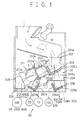
- FIG. 1 is an interior structural drawing showing a coin discriminating device and a coin distributing device of a coin mechanism.
- FIG. 2 is an illustration showing a structure of the coin distributing device and a coin containing part of the coin mechanism.
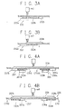
- FIGS. 3A and 3B are cross sectional views showing an action of a second distributing device.
- FIGS. 4A and 4B are cross sectional views showing an action of a sixth distributing device and a seventh distributing device.
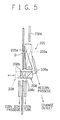
- FIG. 5 is a cross sectional view showing the action of a fifth distributing device and an eighth distributing device.
- FIG. 6 is a block diagram showing a drive control circuit of the coin mechanism.
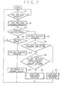
- FIG. 7 is a flow chart showing a temporary holding control of the coin.
- FIGS. 8A to 8D are rough explanation drawings showing a temporary holding action of one coin and a holding release action thereof.
- FIGS. 9A to 9E are rough explanation drawings showing a temporary holding action of two coins and a holding release action thereof.
- FIGS. 1 to FIG. 9 are drawings showing one embodiment of a coin mechanism to which the present invention is applied.
- This coin mechanism is mounted on, for example, a vending machine, and it comprises: a coin discriminating device 10 for discriminating the coin inserted from the coin insert 1 (for example, the coin of ten yen, the coin of fifty yen, the coin of one hundred yen, and the coin of five hundred yen that are Japanese currency); a coin distributing device 20 for distributing the coin discriminated by the coin discriminating device 10; and a coin containing part 30 for containing the coin distributed by the coin distributing device 20, and it performs the money processing for the bought product.
- a coin discriminating device 10 for discriminating the coin inserted from the coin insert 1 (for example, the coin of ten yen, the coin of fifty yen, the coin of one hundred yen, and the coin of five hundred yen that are Japanese currency)
- a coin distributing device 20 for distributing the coin discriminated by the coin discriminating device 10
- a coin containing part 30 for containing the coin distributed by the coin distributing device 20, and it performs the money
- the coin discriminating device 10 sends a signal of a specified frequency to the inserted coin, and on the basis of the change of the received frequency, it judges whether the inserted coin is specie or a forged coin. And furthermore, at the time of judging that the inserted coin is specie, it discriminates the kinds of the coin of one ten yen, the coin of fifty yen, the coin of one hundred yen, and the coin of five hundred yen.
- the coin distributing device 20 comprises first to eighth distributing devices 201 to 208, and the first to eighth distributing devices 201 to 208 are provided in turn along the coin passage through which the inserted coin passes.
- the first distributing device 201 is a device for distributing the inserted coin to the return passage or the second distributing device 202.
- the device 201 works based on the judgment of the specie or the judgment of the forged coin of the inserted coin discriminated by the coin discriminating device 10.
- the first distributing device 201 has a rotating flapper 201a that can rotate, and this rotating flapper 201a is arranged to turn by a solenoid SC1.
- the solenoid SC1 When the solenoid SC1 is in the non-excitation (OFF) state (when it is judged that the inserted coin is a forged coin), the inserted coin passes through the front surface of the rotating flapper 201a, and it is returned to the change outlet through a return passage that is not shown in the figure.
- the solenoid SC1 when the solenoid SC1 is in the excitation (ON) state (when it is judged that the inserted coin is specie), the rotating flapper 201a rotates, and the inserted coin drops toward the second distributing device 202 through the rear side of the rotating flapper 201a.
- the second distributing device 202 is a device for selecting the coin that is distributed by the first distributing device 201 to the coin of one hundred yen and other coins (the coin of ten yen, the coin of fifty yen, and the coin of five hundred yen).
- This second distributing device 202 has front and rear guides 202a, 202b that are branched into two ways, and the guides 202a, 202b are arranged to haunt in the coin passage A by the solenoid SC2.
- this solenoid SC2 is in the non-excitation (OFF) state, as shown in FIG.
- the coin of ten yen, the coin of fifty yen, and the coin of five hundred yen drop on the rear side guide 202b, and furthermore, rolls on the guide 202b to move toward the third distributing device 203.
- the solenoid SC2 when the solenoid SC2 is in the excitation (ON) state, as shown in FIG. 3B, the solenoid SC2 pulls the second distributing device 202 rearward. Consequently, the coin of one hundred yen drops on the front side guide 202a, and rolls on the guide 202a to move toward the fourth distributing device 204.
- the coin tube CT10 for the coin of ten yen and the coin tube CT50 for the coin of fifty yen move toward the fourth distributing device 204.
- the third distributing device 203 is a device for selecting the coin distributed by the second distributing device 202 to the coin of ten yen and the coin of fifty yen, and the coin of five hundred yen.
- This third distributing device 203 has a rotating flapper 203b extending diagonally upward from the rotary shaft 203a.
- a solenoid SC3 is connected, and the rotating flapper 203b is arranged to turn by the solenoid SC3.
- the first temporary holding device 211 is connected to the rotary shaft 203a of this third distributing device 203.
- the first temporary holding device 211 has a bar-shaped rotary arm 211a extending diagonally downward from the rotary shaft 203a, and has a holding projection 211b projecting toward the coin passage A at the tip of the rotary arm 211a.
- the rotating flapper 203b is separated from the coin passage A to open the coin passage A, and in the meantime, the rotary arm 211a rotates toward the coin passage A.
- the tip of the holding projection 211b hits the coin passage A, and as shown in FIGS. 8A, 8B, it prevents the coin from passing through the coin passage A.
- the rotating flapper 203b rotates toward the coin passage A to close the coin passage A, and in the meantime, the rotary arm 211a rotates to be separated from the coin passage A.
- the holding projection 211b is separated from the coin passage A, and as shown in FIG. 8C, that makes it possible for the coin to pass through the coin passage A.
- the second temporary holding device 212 is provided near the rotary shaft 203a in this coin passage A.
- the second temporary holding device 212 is provided so that it may freely haunt to the coin passage A.
- the solenoid SC4 is in the non-excitation (OFF) state, as shown in FIGS. 8A, 8D
- this second temporary holding device 212 projects to the surface of the coin passage A from the rear side of the coin passage A to prevent the coin from passing through the coin passage A.
- the second temporary holding device 212 is in the excitation (ON) state, as shown in FIGS. 8B, 8C, that draws back to the rear side of the coin passage A to make it possible for the coin to pass through the coin passage A.
- the fourth distributing device 204 is a device for distributing the coin of one hundred yen selected by the second distributing device 202 to the coin box passage B and the sixth distributing part 206.
- the fourth distributing device 204 has a rotating flapper 204a that can rotate, and this rotating flapper 204a is arranged to turn by the solenoid SC4 used in the above described second temporary holding device 212.
- the solenoid SC4 is in the excitation (ON) state (when the coin tube CT100 for one hundred yen is filled)
- the rotating flapper 204a rotates. Consequently, the coin of one hundred yen reaching the fourth distributing device 204 is introduced to the coin box passage B through the rear side of the rotating flapper 204a.
- the rotating flapper 204a closes the coin box passage B. Consequently, the coin of one hundred yen reaching the fourth distributing device 204 drops on the surface side of the rotating flapper 204a, and drops toward the sixth distributing device 206. Furthermore, when the coin of ten yen and the coin of fifty yen are distributed by the fourth distributing device 204, the solenoid SC4 is excited, and the coin of ten yen and the coin of fifty yen are introduced to the coin box passage B.
- the fifth distributing device is a device corresponding to the upper distributing device described in the claims.
- the fifth distributing device 205 is a device for distributing the coin of five hundred yen passing through the third distributing device 203 and each of the temporary holding devices 211, 212 to the return passage C and the coin containing passage D.
- This fifth distributing device 205 has a rotating flapper 205a that can rotate, and this rotating flapper 205a is arranged to rotate by the solenoid SC5.
- the solenoid SC5 When the solenoid SC5 is in the excitation (ON) state, the rotating flapper 205a rotates as shown by the solid line in FIG. 5. Consequently, the coin of five hundred yen is introduced to the return passage C as shown by the solid arrow in FIG. 5.
- the sixth distributing device 206, the seventh distributing device 207, and the eighth distributing device 208 are devices to be controlled by the solenoid SC6, and they are formed integrally with the connecting plate 209 connected to this solenoid SC6.
- the sixth distributing device 206 is a device for distributing the coin of one hundred yen distributed by the fourth distributing device 204 to the coin tube CT100 for one hundred yen and the extra tube CT0.
- the sixth distributing device 206 has front and rear guides 206a, 206b that are branched to two ways, and the guides 206a, 206b are arranged to haunt to the coin passage A by the solenoid SC6.
- this solenoid SC6 is in the non-excitation (OFF) state, as shown in FIG.
- the coin of one hundred yen drops on the rear side guide 206b, and furthermore, it rolls on the guide 206b, and after that, it drops to be contained in the coin tube CT100.
- the solenoid SC6 is in the excitation (ON) state, as shown in FIG. 4B, the connecting plate 209 is drawn rearward. Consequently, the coin of one hundred yen drops on the front side guide 206a, and furthermore, it rolls on the guide 206a, and after that, it drops to be contained in the extra coin tube CT0.
- the seventh distributing device 207 is a device for distributing the coins of ten yen and fifty yen distributed by the third distributing device 203 to the coin tube CT10 for ten yen and the coin tube CT50 for fifty yen.
- the seventh distributing device 207 has front and rear guides 207a, 207b that are branched to two ways, and the guides 207a, 207b are arranged to haunt to the coin passage A by the solenoid SC6. When this solenoid SC6 is in the non-excitation (OFF) state, as shown in FIG.
- the coin of one hundred yen drops on the rear side guide 207b, and furthermore, it rolls on the guide 207b, and after that, it drops to be contained in the coin tube CT10 for ten yen.
- the solenoid SC6 is in the excitation (ON) state, as shown in FIG. 4B, the connecting plate 209 is drawn rearward. Consequently, the coin of fifty yen drops on the front side guide 207a, and furthermore, it rolls on the guide 207a, and after that, it drops to be contained in the coin tube CT50 for fifty yen.
- the eighth distributing device 208 is a device corresponding to the lower distributing device described in the claims. As shown in FIG. 2 and FIG. 5, the eighth distributing device 208 is a device for distributing the coin of five hundred yen to the coin box passage B or the coin tube CT500.
- the eighth distributing device 208 is formed integrally with the connecting plate 209, and as shown in FIG. 2, it has forked guide walls 208a, 208b extending in parallel toward the tip. Furthermore, each of the guide walls 208a, 208b has a coin sliding surface diagonally inward, and by this coin sliding surface, the coin of five hundred yen is guided to the outlet 208c at the center of the bottom surface.
- the forged coin is distributed by the first distributing device 201, and it is returned to the change outlet through the return passage.
- the inserted coin of one hundred yen is distributed to the coin box passage B, the coin tube CT100, or the extra coin tube CT0 through the first distributing device 201, the second distributing device 202, the fourth distributing device 204, and the sixth distributing device 206.
- the inserted coin of ten yen is distributed to the coin box passage B or the coin tube CT10 through the first to fourth distributing devices 201 to 204, and the seventh distributing device 207.
- the inserted coin of fifty yen is distributed to the coin box passage B or the coin tube CT50 through the first to fourth distributing devices 201 to 204, and the seventh distributing device 207.
- the above described distributing action of the inserted coin is similar to that in the conventional coin mechanism, and the coin mechanism according to the present embodiment is characterized by the control when the coin of five hundred yen is inserted.
- the drive control circuit for controlling each of the solenoids SC1 to SC6 will be described by referring to FIG. 6. It has a microcomputer 40 as control means of the coin mechanism, and in the microcomputer 40, a timer 40a and a counter 40b are assembled. To the timer 40a, the excitation time at the time when each of the solenoids SC1 to SC6 is ON is set. Furthermore, the counter 40b is set to count the number of inserted coins such as the coin of five hundred yen.
- the following signal is inputted. Whether the inserted coin is specie or a forged coin is judged, and when it is judged that the coin is a forged coin, a judgment signal of the forged coin is inputted from the coin discriminating device 10. Furthermore, when it is judged that the inserted coin is specie, which the inserted coin is among the coin of ten yen, the coin of fifty yen, the coin of one hundred yen, or the coin of five hundred yen is judged, and a judgment signal of the kind of money corresponding to the inserted coin is inputted from the coin discriminating device 10.
- the product select button 41 is a button to be pressed by the customer when buying a product, and when this product select button 41 is pressed, a product buying signal is inputted.
- the over flow sensor 42 is a sensor provided to the coin tube CT500 for five hundred yen, and when the coin tube CT500 is filled with the coins of five hundred yen contained in the coin tube CT500, an over flow signal is inputted.
- the setting device 43 is a setting device for setting the number of containable coins to a small number, for example, setting the number of containable coins of the coin tube CT500 to four, and from this setting device 43, a number setting signal is inputted.
- the switch 44 is a switch for giving a command so that all coins of five hundred yen are contained in the coin box, and a command signal of containing in the coin box is inputted from the switch 44.
- the return lever 45 is a lever to be operated when the customer stops the product buying operation, and when the customer operates the return lever 45, a coin return signal is inputted.
- the microcomputer 40 controls each of the solenoids SC1 to SC6 through the solenoid drive circuit 46 on the basis of these signals, and it performs the temporary holding action and the holding release action of the coin of five hundred yen, and furthermore, the distributing control of the coin of five hundred yen.
- the solenoid SC4 is excited for a specified time, and the second temporary holding device 212 is moved to the rear side of the coin passage A. Consequently, as shown in FIG. 9B, the second temporary holding device 212 is separated from the coin passage A, and the first coin of five hundred yen shown in FIG. 9A rolls toward the first temporary holding device 211b, and it is held by the first temporary holding device 211b. Furthermore, as shown in FIG. 9C, the second coin of five hundred yen is introduced to the rear side of the third distributing device 203, and this second coin of five hundred yen is also held.
- first coin of five hundred yen and the second coin of five hundred yen are brought into contact with each other as shown by the two dot chain line in FIG. 1, and the state is made such that the second coin is held by the first coin (second coin is not brought into contact with the second temporary holding device 212).
- the holding release process of the coin of five hundred yen is performed (S5). In this holding release process, first, whether the number of inserted coins of five hundred yen is one or two is judged. When the number of inserted coins is one, the solenoid SC4 is excited for a specified time, and the second temporary holding device 212 is moved to the rear side of the coin passage A. Consequently, as shown in FIG.
- the holding state of the coin is released, and the coin rolls toward the holding projection 211b of the first temporary holding device 211.
- the solenoid SC4 is excited for a specified time. Consequently, as shown in FIG. 8C, the coin rolls toward the fifth distributing device 205 without being held by the holding projection 211b.
- the third distributing device 203 returns to the waiting state.
- This switch 44 is a switch to be inputted when no bill varidator (not shown in the drawing) is provided and it does not occur for the coin of five hundred yen to be the change.
- the coin box containing switch 44 is ON, containing the coin in the coin tube CT500 is unnecessary, and therefore, the coin box containing process is performed (S7).
- the solenoids SC5, SC6 are excited for a specified time. Consequently, as shown by the broken line in FIG. 5, the fifth distributing device 205 and the eighth distributing device 208 are operated, and the coins of five hundred yen pass through the coin containing passage D, and furthermore, all are contained in the coin box through the coin box passage B.
- This coin containing prohibition command is outputted when the coin tube CT500 is filled on the basis of a detection signal of the over flow sensor 42, and furthermore, it is outputted when the number of coins contained in the coin tube CT500 exceeds the set number of the setting device 43. Furthermore, it is arranged to set either the over flow sensor 42 or the setting device 43.
- a signal from the over flow sensor 42 is received, and on the other hand, in the case where it is arranged to prevent a lot of coins of five hundred yen from being stolen from the coin tube CT500, a signal from the setting device 43 is received.
- the containing of coins of five hundred yen to the coin tube CT500 is controlled, and the above described coin box containing process is performed (S7).
- the coin of five hundred yen is contained in the coin tube CT500 as usual (S9). In this coin tube containing process, only the solenoid SC5 is excited for a specified time, and the coin of five hundred is contained in the coin tube CT500 through the coin containing passage D.
- the coin mechanism according to the present embodiment the coin of five hundred yen whose holding has been released is distributed to the change outlet, the coin box, or the coin tube CT500 at the front stage of entering the coin containing part, and therefore, it is unnecessary to provide another distributing device in the coin tube like the prior art, and the number of coins to be contained in the coin tube CT500 is increased.
- the number of coins to be contained in the coin tube CT500 can be set to a small number.
- the coin mechanism according to the present embodiment is mounted to a vending machine having no bill varidator mounted or the like, it is possible to contain all inserted coins of five hundred yen in the coin box by turning ON the coin box containing command switch 44.
- the microcomputer 40 judges whether a bill varidator is mounted or not, and the eighth distributing device 208 is controlled on the basis of this judgment signal, and all coins of five hundred yen are contained in the coin box, instead of the coin box containing command switch 44.
Landscapes
- Physics & Mathematics (AREA)
- General Physics & Mathematics (AREA)
- Control Of Vending Devices And Auxiliary Devices For Vending Devices (AREA)
Abstract
Description
Claims (4)
- A coin mechanism of a vending machine, comprising:a coin discriminating device (10) for discriminating the kind of a inserted coin;temporary holding devices (211, 212) for temporarily holding a specified coin on a coin passage (A) among coins discriminated by said coin discriminating device (10);distributing devices (205,208) for distributing the coin held by said temporary holding devices (211, 212) to a coin containing part (CT500) or a change outlet; andcontrol means (40) for controlling said temporary holding devices (211, 212) and said distributing devices (205,208),wherein said distributing devices(205,208) include an upper distributing device (205) for distributing the coin to a change outlet or a coin containing passage (D) communicating with said coin containing part (CT500), and a lower distributing device (208) for distributing the coin distributed to said coin containing passage (D) to a coin tube (CT500) or a coin box, andsaid control means (40) can control said upper distributing device (205) so that the inserted coin is distributed toward said change outlet when a coin return command is given and can control said upper distributing device (205) so that the inserted coin is distributed toward said coin containing passage (D) when a product buying command is given, and furthermore, said control means (40) can normally control said lower distributing device (208) so that the inserted coin is distributed toward said coin tube (CT500) and can control said lower distributing device (208) so that the inserted coin is distributed toward said coin box when a containing prohibition command to said coin tube (CT500) is given.
- The coin mechanism according to claim 1, wherein said specified coin is a coin of the largest amount of money among the inserted coins.
- The coin mechanism according to claim 1 or 2, further comprising a coin box containing command switch (44),
wherein said control means (40) can control said lower distributing device (208) so that the inserted coin is distributed toward the coin box on the basis of a containing command signal from said coin box containing command switch (44). - The coin mechanism according to claim 1 or 2, wherein said control means (40) can perform the control so that said lower distributing device (208) distributes the coin toward the coin box when a bill varidator is mounted.
Applications Claiming Priority (2)
| Application Number | Priority Date | Filing Date | Title |
|---|---|---|---|
| JP2000145665A JP4542669B2 (en) | 2000-05-17 | 2000-05-17 | Coin handling equipment |
| JP2000145665 | 2000-05-17 |
Publications (2)
| Publication Number | Publication Date |
|---|---|
| EP1160742A2 true EP1160742A2 (en) | 2001-12-05 |
| EP1160742A3 EP1160742A3 (en) | 2002-12-18 |
Family
ID=18652136
Family Applications (1)
| Application Number | Title | Priority Date | Filing Date |
|---|---|---|---|
| EP01304289A Withdrawn EP1160742A3 (en) | 2000-05-17 | 2001-05-14 | Coin mechanism |
Country Status (3)
| Country | Link |
|---|---|
| US (1) | US6607063B2 (en) |
| EP (1) | EP1160742A3 (en) |
| JP (1) | JP4542669B2 (en) |
Families Citing this family (10)
| Publication number | Priority date | Publication date | Assignee | Title |
|---|---|---|---|---|
| US6520308B1 (en) * | 1996-06-28 | 2003-02-18 | Coinstar, Inc. | Coin discrimination apparatus and method |
| US7635059B1 (en) * | 2000-02-02 | 2009-12-22 | Imonex Services, Inc. | Apparatus and method for rejecting jammed coins |
| FR2834105B1 (en) * | 2001-12-24 | 2004-03-26 | Schlumberger Systems & Service | METHOD FOR MANAGING THE STORAGE IN A STORE OF COINS OF DIFFERENT VALUES |
| EP2187361B1 (en) * | 2008-11-06 | 2015-01-07 | Glory Ltd. | Coin processing unit |
| US9036890B2 (en) | 2012-06-05 | 2015-05-19 | Outerwall Inc. | Optical coin discrimination systems and methods for use with consumer-operated kiosks and the like |
| US8967361B2 (en) | 2013-02-27 | 2015-03-03 | Outerwall Inc. | Coin counting and sorting machines |
| US9022841B2 (en) | 2013-05-08 | 2015-05-05 | Outerwall Inc. | Coin counting and/or sorting machines and associated systems and methods |
| US9443367B2 (en) | 2014-01-17 | 2016-09-13 | Outerwall Inc. | Digital image coin discrimination for use with consumer-operated kiosks and the like |
| JP6227453B2 (en) * | 2014-03-24 | 2017-11-08 | 株式会社日本コンラックス | Coin processing equipment |
| JP2018198010A (en) * | 2017-05-24 | 2018-12-13 | グローリー株式会社 | Coin branching device and coin processing device |
Family Cites Families (18)
| Publication number | Priority date | Publication date | Assignee | Title |
|---|---|---|---|---|
| US3948377A (en) * | 1973-01-17 | 1976-04-06 | Nippon Coinco Co., Ltd. | Coin handling apparatus for a vending machine |
| JPS6057626B2 (en) * | 1976-04-30 | 1985-12-16 | 株式会社日本コインコ | Vending machine control device |
| US4512454A (en) * | 1981-10-29 | 1985-04-23 | Umc Industries, Inc. | Coin apparatus having coin escrow and return means |
| GB2186412B (en) * | 1986-02-12 | 1989-10-25 | Bally Mfg Corp | Bill validation & change system for a slot machine |
| DE3876364T2 (en) * | 1987-10-01 | 1993-06-24 | Sanden Corp | COIN TREATMENT DEVICE. |
| KR890007199A (en) * | 1987-10-01 | 1989-06-19 | 우시구보 도모아끼 | Coin selector |
| JPH0534060Y2 (en) * | 1987-10-08 | 1993-08-30 | ||
| DE3830920A1 (en) * | 1988-09-12 | 1990-03-15 | Harting Elektronik Gmbh | ACCEPTANCE OR RETURN DEVICE OF A COIN ENTERED IN THE COIN CHANNEL OF AN AUTOMATE |
| US5222583A (en) * | 1988-10-06 | 1993-06-29 | Th. Bergmann Gmbh & Co. | Method of monitoring change dispenser operation |
| JP3094228B2 (en) * | 1990-04-18 | 2000-10-03 | 株式会社日本コンラックス | Vending machine control device |
| DE69132067T2 (en) * | 1990-09-20 | 2000-11-16 | Kabushiki Kaisha Nippon Conlux, Tokio/Tokyo | Device for processing coins |
| US5092816A (en) * | 1990-09-25 | 1992-03-03 | Coin Acceptors, Inc. | Coin tube monitor and control means |
| JPH04177494A (en) * | 1990-11-08 | 1992-06-24 | Sanden Corp | Coin processor for automatic vending machine |
| DE4332400C2 (en) * | 1993-09-23 | 2002-11-21 | Nsm Ag | Switch for distributing coins |
| US5579886A (en) * | 1993-10-21 | 1996-12-03 | Kabushiki Kaisha Nippon Conlux | Coin processor |
| GB2326963B (en) * | 1997-07-02 | 2000-08-16 | Mars Inc | Method of operating a money-handling mechanism |
| JP3303771B2 (en) * | 1998-04-01 | 2002-07-22 | 富士電機株式会社 | Coin identification device |
| US6076649A (en) * | 1998-10-01 | 2000-06-20 | Coin Acceptors, Inc. | Programmable multiple coin tube changer |
-
2000
- 2000-05-17 JP JP2000145665A patent/JP4542669B2/en not_active Expired - Lifetime
-
2001
- 2001-05-14 EP EP01304289A patent/EP1160742A3/en not_active Withdrawn
- 2001-05-17 US US09/858,882 patent/US6607063B2/en not_active Expired - Fee Related
Also Published As
| Publication number | Publication date |
|---|---|
| EP1160742A3 (en) | 2002-12-18 |
| US6607063B2 (en) | 2003-08-19 |
| JP4542669B2 (en) | 2010-09-15 |
| JP2001325645A (en) | 2001-11-22 |
| US20020011394A1 (en) | 2002-01-31 |
Similar Documents
| Publication | Publication Date | Title |
|---|---|---|
| US20030080032A1 (en) | Dual cash box note and ticket validator | |
| WO1999022350A1 (en) | Gaming apparatus having note dispenser and method of operating an electronic gaming apparatus | |
| US6607063B2 (en) | Coin discriminating and distributing mechanism | |
| US6702092B2 (en) | Coin assorter | |
| JP2002150364A (en) | Coin processing equipment | |
| JPH11288480A (en) | Coin identification device | |
| JPH0357513B2 (en) | ||
| JP4526156B2 (en) | Coin handling equipment | |
| JP3869614B2 (en) | Coin processing equipment | |
| JP4839549B2 (en) | Coin processing equipment | |
| JP2600069Y2 (en) | Medal thrower | |
| JP2776564B2 (en) | Vending machine coin return device | |
| JP4753271B2 (en) | Banknote handling equipment | |
| JP4244505B2 (en) | Coin processing equipment | |
| JP3369333B2 (en) | Coin processing equipment | |
| JPS6351316B2 (en) | ||
| JP4244506B2 (en) | Coin processing equipment | |
| JP4139084B2 (en) | Coin processing equipment | |
| JPH0246882A (en) | Pachinko device | |
| JPH08147514A (en) | Coin processing equipment | |
| JP3320924B2 (en) | Coin processing equipment | |
| JPH0381190B2 (en) | ||
| JP5430303B2 (en) | Coin handling equipment | |
| JPH0677628B2 (en) | Money insertion device of Takuma ball lending machine | |
| JP2001195638A (en) | Coin processing equipment |
Legal Events
| Date | Code | Title | Description |
|---|---|---|---|
| PUAI | Public reference made under article 153(3) epc to a published international application that has entered the european phase |
Free format text: ORIGINAL CODE: 0009012 |
|
| AK | Designated contracting states |
Kind code of ref document: A2 Designated state(s): AT BE CH CY DE DK ES FI FR GB GR IE IT LI LU MC NL PT SE TR |
|
| AX | Request for extension of the european patent |
Free format text: AL;LT;LV;MK;RO;SI |
|
| PUAL | Search report despatched |
Free format text: ORIGINAL CODE: 0009013 |
|
| AK | Designated contracting states |
Kind code of ref document: A3 Designated state(s): AT BE CH CY DE DK ES FI FR GB GR IE IT LI LU MC NL PT SE TR |
|
| AX | Request for extension of the european patent |
Free format text: AL;LT;LV;MK;RO;SI |
|
| RIC1 | Information provided on ipc code assigned before grant |
Free format text: 7G 07F 5/00 A, 7G 07F 5/24 B, 7G 07F 7/04 B |
|
| 17P | Request for examination filed |
Effective date: 20030606 |
|
| AKX | Designation fees paid |
Designated state(s): ES FR |
|
| REG | Reference to a national code |
Ref country code: DE Ref legal event code: 8566 |
|
| GRAP | Despatch of communication of intention to grant a patent |
Free format text: ORIGINAL CODE: EPIDOSNIGR1 |
|
| STAA | Information on the status of an ep patent application or granted ep patent |
Free format text: STATUS: THE APPLICATION IS DEEMED TO BE WITHDRAWN |
|
| 18D | Application deemed to be withdrawn |
Effective date: 20100605 |