EP1160544A2 - Map display device, map display method, and computer program for use in map display device - Google Patents
Map display device, map display method, and computer program for use in map display device Download PDFInfo
- Publication number
- EP1160544A2 EP1160544A2 EP01304737A EP01304737A EP1160544A2 EP 1160544 A2 EP1160544 A2 EP 1160544A2 EP 01304737 A EP01304737 A EP 01304737A EP 01304737 A EP01304737 A EP 01304737A EP 1160544 A2 EP1160544 A2 EP 1160544A2
- Authority
- EP
- European Patent Office
- Prior art keywords
- map
- information
- display device
- curved surface
- map display
- Prior art date
- Legal status (The legal status is an assumption and is not a legal conclusion. Google has not performed a legal analysis and makes no representation as to the accuracy of the status listed.)
- Granted
Links
Images


Classifications
-
- G—PHYSICS
- G01—MEASURING; TESTING
- G01C—MEASURING DISTANCES, LEVELS OR BEARINGS; SURVEYING; NAVIGATION; GYROSCOPIC INSTRUMENTS; PHOTOGRAMMETRY OR VIDEOGRAMMETRY
- G01C21/00—Navigation; Navigational instruments not provided for in groups G01C1/00 - G01C19/00
- G01C21/26—Navigation; Navigational instruments not provided for in groups G01C1/00 - G01C19/00 specially adapted for navigation in a road network
- G01C21/34—Route searching; Route guidance
- G01C21/36—Input/output arrangements for on-board computers
- G01C21/3626—Details of the output of route guidance instructions
- G01C21/3635—Guidance using 3D or perspective road maps
-
- G—PHYSICS
- G09—EDUCATION; CRYPTOGRAPHY; DISPLAY; ADVERTISING; SEALS
- G09B—EDUCATIONAL OR DEMONSTRATION APPLIANCES; APPLIANCES FOR TEACHING, OR COMMUNICATING WITH, THE BLIND, DEAF OR MUTE; MODELS; PLANETARIA; GLOBES; MAPS; DIAGRAMS
- G09B29/00—Maps; Plans; Charts; Diagrams, e.g. route diagram
- G09B29/10—Map spot or coordinate position indicators; Map reading aids
Definitions
- the present invention relates to a map display device, a map display method, and a computer program for use in a map display device, and in particular relates to road map display techniques used in car navigation devices.
- Example applications for map display devices include a car navigation device.
- a map display device used in a car navigation device needs to enable the user, such as the driver, to comprehend a displayed map at a glance.
- various map display techniques have been devised so that the driver can understand information at once.
- One of such techniques is a method of displaying with emphasis on information which is likely to be desired by the driver.
- a conventional type of map display device displays an enlarged view of a point of interest and its vicinity. For example, when a car is approaching a main intersection, this type of map display device displays an enlarged view of the intersection and its vicinity, to help the driver judge which route he or she should take.
- some map display devices display the enlarged view over a part of a map which is being displayed on a screen, rather than displaying the enlarged view on the whole screen.
- map display devices that display, over a part of a map which is being displayed on a screen, a wide area view of the periphery of an area covered by the map on a larger scale. This method allows the driver to consult the map, and at the same time consult the wide area view to check which roads run around the area covered by the map.
- map display devices emphasize information which is likely to be desired by the driver, by displaying an enlarged view of the vicinity of a point of interest or a wide area view of the periphery of an area shown by a map. In this way, the driver can quickly comprehend information displayed on the screen.
- the driver when displaying the enlarged view of the vicinity of the point of interest on the whole screen, the driver can view the enlarged view but cannot view the map of the area outside the vicinity of the point of interest, and therefore cannot check the roads existing around the vicinity of the point of interest.
- the present invention has an object of providing a map display device that enables a driver to accurately and quickly comprehend map information displayed on a display screen.
- the map display device 10 is a device that maps map information on a curved surface having an intended form, perspective-projects the mapped map information, and displays an image obtained as a result of the projection. In so doing, a map is displayed with a desired portion enlarged or contracted, while maintaining connections of roads.
- the map display device 10 includes a map storing unit 110, a surface storing unit 140, a positional information receiving unit 155, a mapping unit 160, a projecting unit 170, and a displaying unit 180.
- the map display device 10 is implemented by software and hardware provided with a processor, a ROM (Read Only Memory) storing a program, and a working RAM (Random Access Memory).
- ROM Read Only Memory
- RAM Random Access Memory
- the map storing unit 110 stores map information which is made up of image information expressed in bitmap data and character information that includes character strings and designations about the positions of the character strings.
- each character position and each pixel position are expressed using coordinates in a two-dimensional orthogonal coordinate system which covers the entire map information, with such a coordinate system being hereafter referred to as "st coordinate system".
- FIG. 2 shows an example of the image information stored in the map storing unit 110.
- the drawing covers the range of 0 ⁇ s ⁇ 1000 and 0 ⁇ t ⁇ 1000.
- FIG. 3 shows an example of the character information stored in the map storing unit 110.
- Reference numeral 111 is a character information table which lists character strings and positions of the character strings.
- the surface storing unit 140 stores surface information that defines a curved surface which exists in a virtual space where perspective projection is performed (hereafter simply referred to as "virtual space") , and onto which the image information is to be mapped.
- virtual space is represented by a three-dimensional orthogonal coordinate system which is referred to as " xyz coordinate system" in this specification.
- the curved surface defined by the surface information in the surface storing unit 140 is designed so that an angle between a part of the curved surface to which a map portion to be enlarged is mapped and a line of sight in perspective projection is larger than any angles between the other parts of the curved surface and lines of sight in the perspective projection, and an angle between a part of the curved surface to which a map portion to be contracted is mapped and a line of sight in perspective projection is smaller than any angles between the other parts of the curved surface and lines of sight in the perspective projection.
- the effect achieved by this form is detailed in the description of the projecting unit 170.
- the surface storing unit 140 stores the surface information defining the curved surface, in one of the following forms.
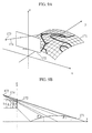
- FIGS. 4A and 4B each show an example curved surface defined by the surface information stored in the surface storing unit 140.
- geodesic lines are provided in 0.1 intervals for both of the x and y coordinates. Note that a curved surface in a virtual space can be similarly defined through the use of the above form (2) or (3) (not illustrated).
- the positional information receiving unit 155 receives car positional information relating to the current position and traveling direction of a car in which the map display device 10 is equipped, from an outside GPS (Global Positioning System) device or inertial navigation device. The positional information receiving unit 155 then outputs the car positional information to the mapping unit 160.
- GPS Global Positioning System
- FIG. 5 shows an example of the car positional information.
- Car positional information 156 is made up of information on the current position and traveling direction of the car.
- the car position is expressed by coordinates in the st coordinate system, and the traveling direction is expressed by an angle measured from the s axis counterclockwise.
- the mapping unit 160 receives the car positional information from the positional information receiving unit 155, calculates an area which is subjected to map display (hereafter called "display target area") in accordance with the received car positional information, and maps image information included in the calculated display target area onto the curved surface defined by the surface information stored in the surface storing unit 140. The details are explained below.
- the mapping unit 160 calculates a rectangular area which contains the current position of the car, as the display target area. As an example, the mapping unit 160 calculates an area having a range of 9km ahead of the car position, 1km to the rear, and 5km to both the left and the right.
- FIG. 6 shows the area calculated by the mapping unit 160.
- reference numeral 157 is the display target area, 158 the car position, and 159 the traveling direction.
- the mapping unit 160 finds a coordinate transformation which corresponds the st coordinates of the display target area to the xy coordinates of the virtual space.
- This transformation is composed of parallel translation and rotation according to the car position and the traveling direction, and contraction.
- the mapping unit 160 calculates the transformation f , based on the amount of parallel translation and the amount of rotation in accordance with the car position and the traveling direction, and the ratio of contraction.
- the mapping unit 160 calculates, for each pixel of the image information included in the display target area, a point (f(s0,t0),z0) on the curved surface to which a pixel at a pixel position (s0,t0) is to be mapped, in the following way.
- the mapping unit 160 maps each pixel of the image information to the obtained position (f(s0,t0),z0) on the curved surface.
- the mapping is conducted using conventional texture mapping.
- mapping unit 160 may be applied to the mapping by the mapping unit 160.
- FIG. 7 shows the result of mapping the image information included in the area 157 shown in FIG. 6, onto the curved surface 141 shown in FIG. 4A.
- FIG. 8 shows the result of mapping the same image information onto the curved surface 142 shown in FIG. 4B.
- geodesic lines are shown in both FIGS. 7 and 8.
- the projecting unit 170 perspective-projects the image information mapped by the mapping unit 160, onto a flat virtual screen. The details are explained below.
- FIG. 9A is a conceptual view showing the perspective projection performed by the projecting unit 170 for the mapping result of FIG. 7, where the positional relations between a curved surface 171, a virtual screen 172, an eyepoint 173, and a line of sight 174 are shown.
- the projecting unit 170 virtually positions the eyepoint 173 before the curved surface 171 in the traveling direction at an appropriate height, and positions the virtual screen 172 so as to provide appropriate vision.
- an image projected on the virtual screen 172 is analogous to a view when looking at an actual geographic area from the sky. This provides a realistic map to the driver, and helps the driver comprehend the perspective.
- Ls denotes the height of the virtual screen 172
- L1 denotes the length at which the nearer half of the curved surface 171 in the traveling direction is projected onto the virtual screen 172.
- L0 the length at which the nearer half of a flat surface which has the same range as the curved surface 171 in x and y coordinates is projected on the virtual screen 172 is shown by L0.
- a nearer part of the curved surface 171 in the traveling direction intersects a line of sight at a large angle ⁇ 1, while a farther part of the curved surface 171 in the traveling direction intersects a line of sight at a small angle ⁇ 2.
- the smaller an angle between the part of the curved surface and the line of sight the smaller an area at which the part of the curved surface is projected onto the virtual screen. Accordingly, in the image obtained as a result of perspective-projecting the map mapped on the curved surface 171, near-by areas are enlarged while distant areas are contracted. This is also demonstrated by L0 ⁇ L1.
- FIG. 10A is a conceptual view showing the perspective projection which is performed by the projecting unit 170 for the mapping result of FIG. 8.
- reference numeral 176 is a curved surface, 177 a virtual screen, 178 an eyepoint, and 179 a line of sight. Their positioning and the effects achieved by it are as described above.
- Ls denotes the height of the virtual screen 177
- L1 denotes the length at which the farther half of the curved surface 176 in the traveling direction is projected on the virtual screen 177
- L0 denotes the length at which the farther half of a flat surface having the same range as the curved surface 176 in x and y coordinates is projected on the virtual screen 177.
- a nearer part of the curved surface 176 in the traveling direction intersects a line of sight at a small angle ⁇ 1
- a farther part of the curved surface 176 in the traveling direction intersects a line of sight at a large angle ⁇ 2 .
- the curved surface is designed so that the angle between the part of the curved surface to which the map portion to be enlarged is mapped and the line of sight in perspective projection is larger than the angles between the other parts of the curved surface and the lines of sight, and the angle between the part of the curved surface to which the map portion to be contracted is mapped and the line of sight in perspective projection is smaller than the angles between the other parts of the curved surface and the lines of sight.
- the displaying unit 180 is equipped with a display screen realized by a liquid crystal panel, a cathode-ray tube, a plasma panel, an EL (electroluminescence) panel, or similar.
- the displaying unit 180 displays the character information and the image which is perspective-projected by the projecting unit 170, onto the display screen. The details are explained below.
- the displaying unit 180 enlarges or contracts the image perspective-projected on the virtual screen, and displays it on the whole display screen.
- the displaying unit 180 calculates a point (f(s0,t0),z0) on the curved surface corresponding to a position (s0,t0) of each character string included in the display target area, in the same way as the mapping unit 160.
- the displaying unit 180 further calculates a point on the virtual screen to which the point (f(s0,t0),z0) on the curved surface is perspective-projected, and displays character fonts of the character string, centering on a point on the display screen corresponding to the calculated point on the virtual screen.
- the map display device 10 does not subject the character fonts to mapping and perspective projection, when displaying the character information.
- the displaying unit 180 displays the character fonts at the position on the display screen determined in the above way, so as to prevent the character fonts from becoming deformed by mapping and perspective projection.
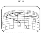
- FIG. 11 shows an example display by the displaying unit 180 for the perspective projection result of FIG. 9, whereas FIG. 12 shows an example display by the displaying unit 180 for the perspective projection result of FIG. 10.
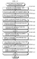
- a map display operation of the map display device 10 is explained below, with reference to FIG. 13.
- the positional information receiving unit 155 outputs the car positional information showing the car position and the traveling direction, to the mapping unit 160 (S101).
- the mapping unit 160 calculates the display target area based on the car position and the traveling direction (S102), and calculates the transformation f from st coordinates to xy coordinates (S103).
- the mapping unit 160 For each pixel of the image information included in the display target area (S104), the mapping unit 160 calculates the mapping position on the curved surface defined by the surface information stored in the surface storing unit 140 using the transformation f (S105), and maps the pixel to the mapping position (S106).
- the projecting unit 170 perspective-projects the image information mapped by the mapping unit 160, onto the virtual screen (S108).
- the displaying unit 180 enlarges or contracts the image perspective-projected on the virtual screen, and displays it on the whole display screen equipped therein (S109). Also, for each character string whose position is included in the display target area (S110), the displaying unit 180 calculates a display position on the screen (S111), and displays character fonts of the character string at the display position (S112).
- the map display device 10 maps the image information on the curved surface, perspective-projects the mapped image information, and displays it. As a result, a map can be displayed with a desired portion enlarged or contracted, while maintaining connections of roads.
- the curved surface is designed so that the angle formed between the part of the curved surface to which the map portion to be enlarged is mapped and the line of sight in perspective projection is larger than the angles formed between the other parts of the curved surface and the lines of sight, and the angle formed between the part of the curved surface to which the map portion to be contracted is mapped and the line of sight in perspective projection is smaller than the angles formed between the other parts of the curved surface and the lines of sight.
- the map display device 10 does not subject the character information to mapping and perspective projection, but directly displays character fonts at corresponding positions on the display screen. As a result, the deformation of the character fonts caused by mapping and perspective projection can be avoided.
- the map display device 20 is a device that provides undulations corresponding to altitudes to a curved surface of an intended form, maps map information onto the curved surface provided with the undulations, perspective-projects the mapped map information, and displays an image obtained as a result of the perspective projection. By doing so, a map which has a desired portion enlarged or contracted while maintaining connections of roads, and which has a three-dimensional appearance, is displayed.
- the features that are the same as those in the first embodiment are omitted, so that the following explanation focuses on the difference with the first embodiment.
- the map display device 20 includes the construction elements of the map display device 10 of the first embodiment, and further includes an altitude storing unit 120. Also, the mapping unit 160 includes a surface deforming unit 161.
- the altitude storing unit 120 stores altitude information which is made up of combinations of positions of altitude points and altitudes of the altitude points.
- FIG. 15 shows an example of the altitude information stored in the altitude storing unit 120.
- An altitude table 121 lists a position and an altitude for each altitude point. Here, the position is expressed in the st coordinate system.
- the mapping unit 160 receives the car positional information from the positional information receiving unit 155, calculates the display target area based on the received car positional information, and maps the image information included in the display target area onto a curved surface deformed by the surface deforming unit 161. The details are explained below.
- the mapping unit 160 calculates the display target area and the transformation f , in the same way as in the first embodiment.
- the mapping unit 160 notifies the surface deforming unit 161 of the display target area and the transformation f , instructs the surface deforming unit 161 to deform the curved surface defined by the surface information stored in the surface storing unit 140, and acquires surface information of the deformed curved surface from the surface deforming unit 161.
- the mapping unit 160 then calculates, for each pixel of the image information included in the display target area, a point (f(s0,t0),z0) on the deformed curved surface to which a pixel at a pixel position (s0, t0) is to be mapped. This calculation is done by bilinear interpolating the coordinates of sample points which are in the vicinity of f(s0,t0) in x and y coordinates, using the information acquired from the surface deforming unit 161. The mapping unit 160 then maps each pixel of the image information to the calculated point (f(s0,t0),z0), as in the first embodiment.
- the surface deforming unit 161 is notified by the mapping unit 160 of the display target area and the transformation f , deforms the curved surface defined by the surface information stored in the surface storing unit 140 in accordance with the altitude information, and outputs the result to the mapping unit 160. The details are explained below.
- the surface deforming unit 161 calculates, for each altitude point included in the display target area, a point (f(s0,t0),z0) on the curved surface corresponding to an altitude point at a position (s0,t0). The surface deforming unit 161 then calculates a point (f(s0,t0),z0+ah) by adding the result of multiplying an altitude h by a constant a, to z0. The surface deforming unit 161 notifies the mapping unit 160 of the calculated point, as a sample point which defines the deformed curved surface.
- the constant a is a scale for altitudes in the xyz coordinate system, and also represents the degree of emphasis on undulations. In other words, the greater the value of a , the more emphasis is placed on undulations.
- FIG. 16 is a conceptual view showing the deformation performed by the surface deforming unit 161.
- reference numeral 165 is the curved surface defined by the surface information stored in the surface storing unit 140, 166 an example point on the curved surface corresponding to a position of an altitude point, 167 a point when the point 166 is moved in the z direction in accordance with the altitude h, and 168 the deformed curved surface.
- the difference with the mean or minimum value of the altitude values included in the display target area may be set as h .
- the sample point may be calculated by interpolating altitudes of neighboring altitude points using bilinear interpolation or the like.
- FIG. 17 shows an example of the mapping result by the mapping unit 160 on the curved surface deformed by the surface deforming unit 161.
- FIG. 18 shows an example display by the displaying unit 180 for the image obtained by perspective-projecting the mapping result of FIG. 17 by the projecting unit 170.
- a map display operation of the map display device 20 is explained below, with reference to FIG. 19.
- the positional information receiving unit 155 outputs the car positional information showing the car position and the traveling direction, to the mapping unit 160 (S201).
- the mapping unit 160 calculates the display target area based on the car position and the traveling direction (S202), and calculates the transformation f (S203).
- the surface deforming unit 161 deforms the curved surface defined by the surface information stored in the surface storing unit 140, in accordance with the altitude information which relates to the display target area (S204).
- the mapping unit 160 For each pixel of the image information included in the display target area (S205), the mapping unit 160 calculates a mapping position on the curved surface deformed by the surface deforming unit 161 (S206), and maps the pixel to the mapping position (S207).
- the projecting unit 170 perspective-projects the image information mapped by the mapping unit 160, onto the virtual screen (S209).
- the displaying unit 180 enlarges or contracts the image perspective-projected on the virtual screen, and displays it on the whole display screen equipped therein (S210). Also, for each character string whose position is included in the display target area (S211), the displaying unit 180 calculates a display position on the display screen (S212), and displays character fonts of the character string at the display position (S213).
- the map display device 20 provides the undulations corresponding to the altitudes to the curved surface having the same form as that in the first embodiment, maps the image information onto the curved surface provided with the undulations, and perspective-projects and displays the mapped image information. As a result, a map can be displayed with a desired portion enlarged or contracted and with a three-dimensional appearance.
- map display device 20 avoids the deformation of the character fonts caused by mapping and perspective projection, as in the first embodiment.
- the map display device 30 is a device that provides undulations corresponding to altitudes to a curved surface of an intended form except a car position and its vicinity, maps map information onto the curved surface provided with the undulations, perspective-projects the mapped map information, and displays an image obtained as a result of the projection. In so doing, a map which has a desired portion enlarged or contracted with connections of roads maintained, and which has a three-dimensional appearance, is displayed.
- the map display device 30 also prevents the map display around the car position from being hidden by the undulations.
- the surface deforming unit 161 includes an altitude changing unit 162.
- the surface deforming unit 161 deforms the curved surface defined by the surface information stored in the surface storing unit 140, in accordance with altitude information which is changed by the altitude changing unit 162, and outputs the result to the mapping unit 160.
- the altitude changing unit 162 sets a flat area which contains the car position and its vicinity, changes altitudes of altitudes points in the flat area to a uniform value, and changes altitudes of altitudes points around the flat area according to their distances from the flat area. The details are explained below.
- the altitude changing unit 162 calculates a rectangular area which is a part of the display target area and which contains the car position, as the flat area. As an example, the altitude changing unit 162 calculates an area having a range of 5km ahead of the car position and 1km to both the left and the right.
- the altitude changing unit 162 changes altitudes of all altitude points in the flat area, to the lowest altitude value hlow in the flat area.
- FIG. 21 shows an example of the curved surface deformed by the surface deforming unit 161 using the changed altitude information.
- a diagonally shaded region is the flat area. Since altitudes of altitude points in the flat area are changed to the uniform value, no undulations are provided in that area. This suppression of undulations is gradually removed around the flat area, depending on distances from the flat area.
- FIG. 22 shows an example of the mapping result by the mapping unit 160 on the curved surface deformed by the surface deforming unit 161.
- FIG. 23 shows an example display by the displaying unit 180 for the image obtained by perspective-projecting the mapping result of FIG. 22 by the projecting unit 170.
- the map display device 30 suppresses the provision of undulations in the flat area, so that roads existing ahead of the flat area can be displayed without being obstructed by a mountain and the like.
- the effect achieved by this construction is remarkable, when compared with the example display shown in FIG. 18 in the second embodiment.
- a map display operation of the map display device 30 is explained below, with reference to FIG. 24.
- the positional information receiving unit 155 outputs the car positional information showing the car position and the traveling direction, to the mapping unit 160 (S301).
- the mapping unit 160 calculates the display target area based on the car position and the traveling direction (S302), and calculates the transformation f (S303).
- the altitude changing unit 162 changes the altitudes in the flat area to the uniform value, and changes the altitudes in the vicinity of the flat area in accordance with the distances from the flat area (S304).
- the surface deforming unit 161 deforms the curved surface defined by the surface information stored in the surface storing unit 140, according to the altitude information changed by the altitude changing unit 162 (S305).
- the mapping unit 160 For each pixel of the image information included in the display target area (S306), the mapping unit 160 calculates a mapping position on the curved surface deformed by the surface deforming unit 161 (S307), and maps the pixel to the mapping position (S308).
- the projecting unit 170 perspective-projects the image information mapped by the mapping unit 160, onto the virtual screen (S310).
- the displaying unit 180 enlarges or contracts the image perspective-projected on the visual screen, and displays it on the whole display screen equipped therein (S311). Also, for each character string whose position is included in the display target area (S312), the displaying unit 180 calculates a display position on the display screen (S313), and displays character fonts of the character string at the display position (S314).
- the map display device 30 provides the undulations corresponding to the altitudes to the curved surface having the same form as that of the second embodiment, except the car position and its vicinity.
- the map display device 30 maps the image information onto the curved surface provided with the undulations, and perspective-projects and displays the mapped image information.
- a map can be displayed with a desired portion enlarged or contracted and with a three-dimensional appearance.
- the map display device 30 suppresses the display of undulations around the car position, to prevent the map from being obstructed by the undulations.
- map display device 30 avoids the deformation of the character fonts caused by mapping and perspective projection, as in the first embodiment.
- the map display device 40 is a device that perspective-projects map information onto a virtual screen having an intended curved surface form, projects an image obtained by the perspective projection onto a display screen, and displays it. In so doing, a map is displayed with a desired portion enlarged or contracted, while maintaining connections of roads.
- the same features as those in the first embodiment are omitted, and the following explanation focuses on the difference.
- the map display device 40 includes a map storing unit 210, a surface storing unit 240, a positional information receiving unit 255, a projecting unit 270, and a displaying unit 280.
- the map storing unit 210 is the same as the map storing unit 110 in the first embodiment, and stores map information made up of image information and character information.
- the positional information receiving unit 255 receives car positional information relating to a current position and traveling direction of a car in which the map display device 40 is equipped, from an outside device such as a GPS or inertial navigation device. The positional information receiving unit 255 then outputs the car positional information to the projecting unit 270.
- the structure of the car positional information is the same as that in the first embodiment.
- the surface storing unit 240 stores surface information that defines a curved surface which exists within a virtual space and which serves as a virtual screen for perspective projection.
- the virtual space is expressed using the three-dimensional orthogonal coordinate system called "xyz coordinate system", as in the first embodiment.
- the curved surface is designed such that an angle between a part of the curved surface to which a map portion to be enlarged is perspective-projected and a line of sight in perspective projection is smaller than any angles between the other parts of the curved surface and lines of sight, and an angle between a part of the curved surface to which a map portion to be contracted is perspective-projected and a line of sight in perspective projection is larger than any angles between the other parts of the curved surface and lines of sight.
- the effect achieved by such a form is detailed in the description of the projecting unit 270.
- the surface storing unit 240 stores the surface information defining the curved surface in one of the following forms, as in the first embodiment.
- FIGS. 26A and 26B each show an example curved surface defined by the surface information stored in the surface storing unit 240.
- geodesic lines are provided in 0.1 intervals for both of the x and y coordinates. Note that a curved surface in a virtual space can be similarly defined through the use of the above form (2) or (3) (not illustrated).
- the projecting unit 270 calculates a display target area based on the car positional information received from the positional information receiving unit 255, and perspective-projects the image information included in the display target area, onto the virtual screen of the curved surface form defined by the surface information stored in the surface storing unit 240.
- This perspective projection is equivalent to an operation of mapping a map onto a curved surface. The details are explained below.
- the projecting unit 270 calculates a rectangular area including the car position as the display target area, as in the first embodiment.
- FIG. 6 shows an example of the calculated area.
- the projecting unit 270 then obtains a coordinate transformation which associates the st coordinates of the display target area to the xy coordinates of the virtual space.
- This transformation is composed of parallel translation and rotation in accordance with the car position and the traveling direction, and contraction.
- the projecting unit 270 calculates the transformation f , based on the parallel translation amount and the rotation amount in accordance with the car position and the traveling direction, and the contraction ratio.
- FIG. 27 shows an example of the image information which is obtained by coordinate-transforming the image information included in the display target area of FIG. 6 using the transformation f , and positioned in the virtual space.
- FIG. 28A is a conceptual view showing the perspective projection which is performed by the projecting unit 270 on the virtual screen shown in FIG. 26A, where the positional relations between a flat surface 271, a virtual screen 272, an eyepoint 273, and a line of sight 274 are shown.
- the projecting unit 270 virtually positions the eyepoint 273 before the flat surface 271 in the traveling direction at an appropriate height, and positions the virtual screen 272 so as to obtain appropriate vision.
- an image projected on the virtual screen 272 is analogous to a view when looking at an actual geographic area from the sky. This provides a realistic map to the driver and helps him or her comprehend the perspective.
- Ls is the height of the virtual screen 272
- L1 is the length at which the nearer half of the flat surface 271 in the traveling direction is projected on the virtual screen 272.
- L0 the length at which the nearer half of the flat surface 271 in the traveling direction is projected on a flat virtual screen having the same range as the virtual screen 272 in x and y coordinates is shown by L0.
- the virtual screen 272 intersects a line of sight directed to a nearer part of the flat surface 271 in the traveling direction at a small angle ⁇ 1 , and intersects a line of sight directed to a farther part of the flat surface 271 in the traveling direction at a large angle ⁇ 2.
- the smaller an angle formed between the virtual screen and a line of sight the larger an area perspective-projected on the virtual screen is. Therefore, in the image obtained by perspective-projecting the map on the flat surface 271, near-by areas are enlarged and distant areas are contracted. This is also clear from L0 ⁇ L1.
- FIG. 29A is a conceptual view showing the perspective projection on the virtual screen of FIG. 26B, where reference numeral 276 is a flat surface, 277 a virtual screen, 278 an eyepoint, and 279 a line of sight. Their positioning and the effects achieved by it are as described above.
- Ls denotes the height of the virtual screen 277
- L1 denotes the length at which the farther half of the flat surface 276 in the traveling direction is projected on the virtual screen 277
- L0 denotes the length at which the farther half of the flat surface 276 is projected on a flat virtual screen having the same range as the virtual screen 277 in x and z coordinates.
- the virtual screen 277 intersects a line of sight which is directed to a nearer part of the flat surface 276 in the traveling direction at a large angle ⁇ 1, and intersects a line of sight which is directed to a farther part of the flat surface 276 in the traveling direction at a small angle ⁇ 2. Accordingly, in the image obtained by perspective-projecting the map on the flat surface 276, near-by areas are contracted while distant areas are enlarged. This is also clear from L0 ⁇ L1.
- the curved surface is designed such that the angle formed between the part of the curved surface to which the map portion to be enlarged is perspective-projected and the line of sight in perspective projection is smaller than the angles formed between the other parts of the curved surface and the lines of sight, and the angle formed between the part of the curved surface to which the map portion to be contracted is perspective-projected and the line of sight in perspective projection is larger than the angles formed between the other parts of the curved surface and the lines of sight.
- the displaying unit 280 is equipped with a display screen realized by a liquid crystal panel, a cathode-ray tube, a plasma panel, an EL panel, or similar, and displays the character information and the image which is perspective-projected by the projecting unit 270, on the display screen. The details are explained below.
- the displaying unit 280 projects the image perspective-projected on the virtual screen, onto the display screen, and displays it.
- the displaying unit 280 calculates, for each character string whose position is included in the display target area, a point on the virtual screen to which a point (f(s0,t0),0) obtained by expressing a character position (s0,t0) in the xyz coordinate system is perspective-projected.
- the displaying unit 280 further calculates a point on the display screen to which the point on the virtual screen is projected, and displays character fonts of the character string, centering on the calculated point on the display screen.
- the map display device 40 avoids the deformation of the character fonts caused by mapping and perspective projection, as in the first embodiment.
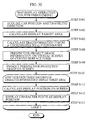
- a map display operation of the map display device 40 is explained below, with reference to FIG. 30.
- the positional information receiving unit 255 outputs the car positional information showing the car position and the traveling direction, to the projecting unit 270 (S401).
- the projecting unit 270 calculates the display target area based on the car position and the traveling direction (S402), and calculates the transformation f from st coordinates to xy coordinates of the virtual space (S403).
- the projecting unit 270 positions the image information included in the display target area, in the virtual space using the transformation f.
- the projecting unit 270 then perspective-projects the image information onto the virtual screen defined by the surface information stored in the surface storing unit 240 (S408).
- the displaying unit 280 projects the image perspective-projected on the virtual screen, onto the display screen equipped therein, and displays it (S409). Also, for each character string whose position is included in the display target area (S410), the displaying unit 280 calculates a display position on the display screen (S411), and displays character fonts of the character string at the display position (S412).
- the map display device 40 perspective-projects the image information onto the virtual screen having the curved surface form, projects the perspective-projected image onto the display screen, and displays it. As a result, a map is displayed with a desired portion enlarged or contracted, while maintaining connections of roads.
- the curved surface is designed so that the. angle formed between the part of the curved surface to which the map portion to be enlarged is perspective-projected and the line of sight in perspective projection is smaller than the angles formed between the other parts of the curved surface and the lines of sight, and the angle formed between the part of the curved surface to which the map portion to be contracted is perspective-projected and the line of sight in perspective projection is larger than the angles formed between the other parts of the curved surface and the lines of sight.
- map display device 40 avoids the deformation of the character fonts caused by mapping and perspective projection, as in the first embodiment.
- the map display device 50 is a device that provides undulations according to altitudes to map information, perspective-projects the map information provided with the undulations onto a virtual screen having an intended curved surface form, projects an image obtained by the perspective projection onto a display screen, and displays it. By doing so, a map is displayed with a desired portion enlarged or contracted while maintaining connections of roads, and with a three-dimensional appearance.
- the same features as the first, second, and fourth embodiments are omitted, so that the following explanation focuses on the difference with these embodiments.
- the map display device 50 includes the construction elements of the map display device 40 of the fourth embodiment, and further includes an altitude storing unit 220. Also, the projecting unit 270 includes a map deforming unit 261.
- the altitude storing unit 220 is the same as the altitude storing unit 120 in the second embodiment.
- the altitude storing unit 220 has the altitude table 121 shown in FIG. 15, and stores a position and an altitude for each altitude point.
- the map deforming unit 261 is notified by the projecting unit 270 of the display target area and the transformation f, and provides undulations according to the altitude information to the image information included in the display target area, in the virtual space.
- the map deforming unit 261 then outputs the result to the projecting unit 270. The details are explained below.
- the map deforming unit 261 For each altitude point included in the display target area, the map deforming unit 261 calculates a point (f(s0,t0),0) in the virtual space corresponding to a position (s0,t0) of the altitude point, and calculates a point (f(s0,t0),ah) by adding the result of multiplying an altitude h by a constant a , to the z coordinate. The map deforming unit 261 then notifies the projecting unit 270 of the calculated point, as a sample point which defines the deformed image information.
- the constant a is a scale for altitudes in the xyz coordinate system, and also represents the degree of emphasis on undulations. In other words, the greater the value of a, the more emphasis is placed on the undulations.
- the difference with the mean or minimum value of the altitude values included in the display target area may be set as h .
- the sample point may be calculated by interpolating altitude values of neighboring altitude points using bilinear interpolation or the like.
- the projecting unit 270 calculates the display target area based on the car positional information received from the positional information receiving unit 255, and perspective-projects the deformed image information obtained by deforming the image information included in the display target area by the map deforming unit 261, onto the virtual screen whose form is defined by the surface information stored in the surface storing unit 240. The details are explained below.
- the projecting unit 270 calculates the display target area and the transformation f , as in the fourth embodiment.
- the projecting unit 270 notifies the map deforming unit 261 of the display target area and the transformation f , and instructs the map deforming unit 261 to provide undulations according to the altitude information to the image information included in the display target area, in the virtual space.
- the projecting unit 270 then acquires the deformed image information from the map deforming unit 261.
- the projecting unit 270 perspective-projects the deformed image information, in the same way as in the fourth embodiment.
- a map display operation of the map display device 50 is explained below, with reference to FIG. 32.
- the positional information receiving unit 255 outputs the car positional information showing the car position and the traveling direction, to the projecting unit 270 (S501).
- the projecting unit 270 calculates the display target area based on the car position and the traveling direction (S502), and calculates the transformation f from st coordinates to xy coordinates of the virtual space (S503).
- the map deforming unit 261 provides undulations according to the altitude information to the image information included in the display target area, in the virtual space (S504).
- the projecting unit 270 perspective-projects the image information provided with the undulations, onto the virtual screen defined by the surface information stored in the surface storing unit 240 (S509).
- the displaying unit 280 projects and displays the image perspective-projected on the virtual screen, onto the display screen equipped therein (S510). Also, for each character string whose position is included in the display target area (S511), the displaying unit 280 calculates a display position on the display screen (S512), and displays character fonts of the character string at the display position (S513).
- the map display device 50 provides the undulations according to the altitudes to the image information, perspective-projects the image information provided with the undulations onto the virtual screen which has the same form as that the fourth embodiment, projects the perspective-projected image onto the display screen, and displays it.
- a map can be displayed with a desired portion enlarged or contracted and with a three-dimensional appearance.
- map display device 50 avoids the deformation of the character fonts caused by mapping and perspective projection, in the same manner as in the first embodiment.
- the map display device 60 is a device that provides undulations according to altitudes to map information except the car position and its vicinity, perspective-projects the resulting map information onto a virtual screen having an intended curved surface form, and projects and displays an image obtained as a result of the perspective projection. In so doing, a map is displayed with a desired portion enlarged or contracted while maintaining connections of roads, and with a three-dimensional appearance.
- the map display device 60 further prevents the map display around the car position from being obstructed by the undulations.
- the same features as the first, third, and fifth embodiments are omitted, so that the following explanation focuses on the difference with these embodiments.
- the map deforming unit 261 includes an altitude changing unit 262.
- the map deforming unit 261 is notified by the projecting unit 270 of the display target area and the transformation f .
- the map deforming unit 261 provides undulations according to altitude information changed by the altitude changing unit 262, to the image information included in the display target area in the virtual space, in the same way as the fifth embodiment.
- the map deforming unit 261 then outputs the result to the projecting unit 270.
- the altitude changing unit 262 is the same as the altitude changing unit 162 in the third embodiment.
- the altitude changing unit 262 sets a flat area which contains the car position and its vicinity, changes altitudes of altitudes points in the flat area to a uniform value, and changes altitudes of altitude points around the flat area according to their distances from the flat area.
- a map display operation of the map display device 60 is explained below, with reference to FIG. 34.
- the positional information receiving unit 255 outputs the car positional information showing the car position and the traveling direction, to the projecting unit 270 (S601).
- the projecting unit 270 calculates the display target area based on the car position and the traveling direction (S602), and calculates the transformation f from st coordinates to xy coordinates of the virtual space (S603).
- the altitude changing unit 262 changes the altitudes of the altitude points in the flat area to the uniform value, and changes the altitudes of the altitude points around the flat area depending on their distances from the flat area (S604)
- the map deforming unit 261 provides undulations according to the changed altitude information to the image information included in the display target area, in the virtual space (S605).
- the projecting unit 270 perspective-projects the deformed image information onto the virtual screen defined by the surface information stored in the surface storing unit 240 (S610).
- the displaying unit 280 projects and displays the image perspective-projected on the virtual screen, onto the display screen equipped therein (S611). Also, for each character string whose position is included in the display target area (S612), the displaying unit 280 calculates a display position on the display screen (S613), and displays character fonts of the character string at the display position (S614).
- the map display device 60 provides the undulations corresponding to the altitudes to the image information except the car position and its vicinity, perspective-projects the image information provided with the undulations onto the virtual screen having the same curved surface form as in the fifth embodiment, and projects and displays the perspective-projected image onto the display screen.
- a map can be displayed with a desired portion enlarged or contracted and with a three-dimensional appearance.
- the map display device 60 keeps the map display from being obstructed by the undulations, by restricting the display of the undulations around the car position.
- map display device 60 avoids the deformation of the character fonts caused by mapping and perspective projection, as in the first embodiment.
- the map display device ordinarily displays a map of an area specified by the current position of the car, and upon receiving an instruction from the driver, temporarily displays a map of the vicinity of a destination or the like. This benefits the convenience of drivers.
Landscapes
- Engineering & Computer Science (AREA)
- Radar, Positioning & Navigation (AREA)
- Remote Sensing (AREA)
- Physics & Mathematics (AREA)
- Theoretical Computer Science (AREA)
- General Physics & Mathematics (AREA)
- Automation & Control Theory (AREA)
- Educational Administration (AREA)
- Educational Technology (AREA)
- Business, Economics & Management (AREA)
- Mathematical Physics (AREA)
- Instructional Devices (AREA)
- Navigation (AREA)
- Processing Or Creating Images (AREA)
- Control Of Indicators Other Than Cathode Ray Tubes (AREA)
Abstract
Description
Claims (26)
- A map display device, characterized by
mapping a map of an area which is specified by a current position of the map display device or by an instruction from a user, onto a curved surface to generate a mapped image, and displaying the mapped image. - The map display device of Claim 1,wherein the map has at least one portion which is to be enlarged and/or at least one portion which is to be contracted, the portion to be enlarged and the portion to be contracted being referred to as an enlarged portion and a contracted portion respectively, andthe curved surface has a form which depends on a positioning of the enlarged portion and/or the contracted portion on the map.
- The map display device of Claim 2, comprising:map storing means for storing map information;map acquiring means for acquiring map information that shows the map of the area specified by the current position of the map display device, from the map storing means;surface storing means for storing surface information that defines the curved surface whose form depends on the positioning of the enlarged portion and/or the contracted portion on the map shown by the acquired map information;mapping means for mapping the map shown by the acquired map information, onto the curved surface defined by the surface information, to generate the mapped image; andprojecting/displaying means for projecting the mapped image onto a flat virtual screen, and displaying the projected image.
- The map display device of Claim 3,
wherein the curved surface defined by the surface information has the following property:
when the map is mapped onto the curved surface by the mapping means and projected onto the virtual screen by the projecting/displaying means,(a) an angle formed between a part of the curved surface to which the enlarged portion of the map is mapped and a line of sight directed to the part of the curved surface in the projection is larger than any angles formed between other parts of the curved surface and lines of sight directed to the other parts of the curved surface in the projection, and(b) an angle formed between a part of the curved surface to which the contracted portion of the map is mapped and a line of sight directed to the part of the curved surface in the projection is smaller than any angles formed between other parts of the curved surface and lines of sight directed to the other parts of the curved surface in the projection. - The map display device of Claim 4, further comprisingaltitude storing means for storing altitude information showing a correspondence between positions of points shown in the map and altitudes of the points,the mapping means includesa surface deforming unit for providing undulations corresponding to the altitudes shown by the altitude information, to the curved surface at positions to which the points on the map at the corresponding positions shown by the altitude information are to be mapped, to generate a deformed curved surface, andthe mapping means maps the map onto the deformed curved surface.
- The map display device of Claim 5,wherein the surface deforming unit includesan altitude changing unit for changing altitudes in the altitude information that correspond to positions included in a first area which is made up of the current position of the map display device in the map and a neighborhood thereof, to a uniform value, andthe surface deforming unit generates the deformed curved surface, using the changed altitude information.
- The map display device of Claim 6,
wherein the altitude changing unit further changes altitudes in the altitude information that correspond to positions included in an area around the first area, in accordance with distances of the positions from the first area. - The map display device of Claim 3, further comprisingsurface receiving means for receiving the surface information,wherein the surface storing means stores the surface information received by the surface receiving means.
- The map display device of Claim 3,wherein the projecting/displaying means includesa projection position storing unit for storing a correspondence between positions on the curved surface and positions on the virtual screen to which points at the positions on the curved surface are to be projected.
- The map display device of Claim 3,wherein the map information stored in the map storing means includes (a) image information showing an image in which graphics representative of objects are drawn in correspondence with positions of the objects on the ground surface, and (b) character information showing a correspondence between character strings relating to the objects and the positions of the objects on the ground surface,the map acquiring means acquires image information and character information which relate to the map of the area specified by the current position of the map display device, from the map storing means,the map display device further comprisescharacter display position calculating means for calculating points on the curved surface to which points on the map at positions shown by the acquired character information are mapped, and calculating positions on the virtual screen to which the calculated points on the curved surface are projected,the mapping means maps an image shown by the acquired image information, to generate the mapped image, andthe projecting/displaying means further displays character strings shown by the acquired character information, with reference to the calculated positions.
- The map display device of Claim 3 being mounted on a movable body, and further comprisingpositional information receiving means for receiving positional information showing a current position and a traveling direction of the movable body,wherein the map acquiring means acquires the map information showing the map of the area specified by the positional information received by the positional information receiving means, from the map storing means.
- The map display device of Claim 11, further comprisingmap receiving means for receiving map information transmitted by radio,wherein the map storing means stores the map information received by the map receiving means.
- The map display device of Claim 2, comprising:map storing means for storing map information;map acquiring means for acquiring map information that shows the map of the area specified by the current position of the map display device, from the map storing means;surface storing means for storing surface information that defines a virtual screen having the form of the curved surface which depends on the positioning of the enlarged portion and/or the contracted portion on the map shown by the acquired map information; andprojecting/displaying means for projecting the map shown by the acquired map information onto the virtual screen defined by the surface information, and displaying a projected image obtained as a result of the projection.
- The map display device of Claim 13,wherein the virtual screen defined by the surface information has the following property:when the map is projected onto the virtual screen by the projecting/displaying means,(a) an angle formed between a part of the virtual screen to which the enlarged portion of the map is projected and a line of sight directed to the part of the virtual screen in the projection is smaller than any angles formed between other parts of the virtual screen and lines of sight directed to the other parts of the virtual screen in the projection, and(b) an angle formed between a part of the virtual screen to which the contracted portion of the map is projected and a line of sight directed to the part of the virtual screen in the projection is larger than any angles formed between other parts of the virtual screen and lines of sight directed to the other parts of the virtual screen in the projection.
- The map display device of Claim 14, further comprisingaltitude storing means for storing altitude information showing a correspondence between positions of points shown in the map and altitudes of the points,the projecting/displaying means includesa map deforming unit for providing undulations corresponding to the altitudes shown by the altitude information, to the map at the corresponding positions shown by the altitude information, to generate a deformed map, andthe projecting/displaying means projects the deformed map onto the virtual screen.
- The map display device of Claim 15,wherein the map deforming unit includesan altitude changing unit for changing altitudes in the altitude information that correspond to positions included in a first area which is made up of the current position of the map display device in the map and a neighborhood thereof, to a uniform value, andthe map deforming unit generates the deformed map, using the changed altitude information.
- The map display device of Claim 16,
wherein the altitude changing unit further changes altitudes in the altitude information that correspond to positions included in an area around the first area, in accordance with distances of the positions from the first area. - The map display device of Claim 13, further comprisingsurface receiving means for receiving the surface information,wherein the surface storing means stores the surface information received by the surface receiving means:
- The map display device of Claim 13,wherein the projecting/displaying means includesa projection position storing unit for storing a correspondence between positions on the map and positions on the virtual screen to which points at the positions on the map are to be projected.
- The map display device of Claim 13,wherein the map information stored in the map storing means includes (a) image information showing an image in which graphics representative of objects are drawn in correspondence with positions of the objects on the ground surface, and (b) character information showing a correspondence between character strings relating to the objects and the positions of the objects on the ground surface,the map acquiring means acquires image information and character information which relate to the map of the area specified by the current position of the map display device, from the map storing means,the map display device further comprisescharacter display position calculating means for calculating positions on the virtual screen to which points on the map at positions shown by the acquired character information are to be projected, andthe projecting/displaying means projects an image shown by the acquired image information, to generate the projected image, and displays character strings shown by the acquired character information, with reference to the calculated positions.
- The map display device of Claim 13 being mounted on a movable body, and further comprisingpositional information receiving means for receiving positional information showing a current position and a traveling direction of the movable body,wherein the map acquiring means acquires the map information showing the map of the area specified by the positional information received by the positional information receiving means, from the map storing means.
- The map display device of Claim 21, further comprisingmap receiving means for receiving map information transmitted by radio,wherein the map storing means stores the map information received by the map receiving means.
- A map display method for use in a map display device for displaying a map with one or more portions enlarged and/or contracted, comprising:a map receiving step for receiving map information that shows a map of an area specified by a current position of the map display device, wherein surface information that defines a curved surface whose form depends on a positioning of one or more portions to be enlarged and/or contracted on the map shown by the map information is stored in a storing unit in the map display device;a mapping step for mapping the map shown by the map information, onto the curved surface defined by the surface information, to generate a mapped image; anda projecting/displaying step for projecting the mapped image onto a flat virtual screen, and displaying the projected image.
- A map display method for use in a map display device for displaying a map with one or more portions enlarged and/or contracted, comprising:a map receiving step for receiving map information that shows a map of an area specified by a current position of the map display device, wherein surface information that defines a virtual screen having a form of a curved surface which depends on a positioning of one or more portions to be enlarged and/or contracted on the map shown by the map information is stored in a storing unit in the map display device; anda projecting/displaying step for projecting the map shown by the map information onto the virtual screen defined by the surface information, and displaying a projected image obtained as a result of the projection.
- A computer program recorded on a computer-readable recording medium, for use in a map display device that displays a map with one or more portions enlarged and/or contracted, the program comprising:a map receiving step for receiving map information that shows a map of an area specified by a current position of the map display device, wherein surface information that defines a curved surface whose form depends on a positioning of one or more portions to be enlarged and/or contracted on the map shown by the map information is stored in a storing unit in the map display device;a mapping step for mapping the map shown by the map information, onto the curved surface defined by the surface information, to generate a mapped image; anda projecting/displaying step for projecting the mapped image onto a flat virtual screen, and displaying the projected image.
- A computer program recorded on a computer-readable recording medium, for use in a map display device that displays a map with one or more portions enlarged and/or contracted, the program comprising:a map receiving step for receiving map information that shows a map of an area specified by a current position of the map display device, wherein surface information that defines a virtual screen having a form of a curved surface which depends on a positioning of one or more portions to be enlarged and/or contracted on the map shown by the map information is stored in a storing unit in the map display device; anda projecting/displaying step for projecting the map shown by the map information onto the virtual screen defined by the surface information, and displaying a projected image obtained as a result of the projection.
Applications Claiming Priority (2)
| Application Number | Priority Date | Filing Date | Title |
|---|---|---|---|
| JP2000160032 | 2000-05-30 | ||
| JP2000160032 | 2000-05-30 |
Publications (3)
| Publication Number | Publication Date |
|---|---|
| EP1160544A2 true EP1160544A2 (en) | 2001-12-05 |
| EP1160544A3 EP1160544A3 (en) | 2007-11-14 |
| EP1160544B1 EP1160544B1 (en) | 2009-03-11 |
Family
ID=18664284
Family Applications (1)
| Application Number | Title | Priority Date | Filing Date |
|---|---|---|---|
| EP01304737A Expired - Lifetime EP1160544B1 (en) | 2000-05-30 | 2001-05-30 | Map display device, map display method, and computer program for use in map display device |
Country Status (3)
| Country | Link |
|---|---|
| US (1) | US6650253B2 (en) |
| EP (1) | EP1160544B1 (en) |
| DE (1) | DE60137886D1 (en) |
Cited By (3)
| Publication number | Priority date | Publication date | Assignee | Title |
|---|---|---|---|---|
| WO2007031361A1 (en) * | 2005-09-12 | 2007-03-22 | Robert Bosch Gmbh | Method for the three-dimensional representation of a vector map of a screen navigation system |
| EP1195577A3 (en) * | 2000-10-06 | 2008-12-03 | Panasonic Corporation | Map display device, map display method, and computer program for use in map display device |
| EP2302324A3 (en) * | 2009-09-25 | 2012-02-29 | Navigon AG | Method for operating a navigation system |
Families Citing this family (8)
| Publication number | Priority date | Publication date | Assignee | Title |
|---|---|---|---|---|
| JP2002311821A (en) * | 2001-04-13 | 2002-10-25 | Mitsubishi Electric Corp | Map display method and navigation device for navigation |
| US9360990B1 (en) * | 2003-09-09 | 2016-06-07 | James A. Roskind | Location-based applications |
| JP2006071619A (en) * | 2004-08-03 | 2006-03-16 | Denso Corp | Navigation device and program |
| CN102667407B (en) * | 2010-10-28 | 2015-03-18 | 丰田博图导航信息技术有限公司 | Tunnel entrance elevation specifying device, method for specifying tunnel entrance elevation |
| US8869058B1 (en) * | 2012-05-25 | 2014-10-21 | Google Inc. | Interface elements for specifying pose information for photographs in an online map system |
| US10171768B2 (en) | 2015-08-06 | 2019-01-01 | International Business Machines Corporation | Curve profile control for a flexible display |
| US10297234B2 (en) | 2016-03-11 | 2019-05-21 | International Business Machines Corporation | Curved virtual display surface for displaying digital objects |
| CN110490931A (en) * | 2019-08-20 | 2019-11-22 | 上海秒针网络科技有限公司 | Orbit generation method and device, storage medium and electronic device |
Family Cites Families (5)
| Publication number | Priority date | Publication date | Assignee | Title |
|---|---|---|---|---|
| DE69628091T2 (en) * | 1995-06-13 | 2004-04-01 | Matsushita Electric Industrial Co., Ltd., Kadoma | Vehicle navigation device and recording medium for program storage therefor |
| US5874905A (en) * | 1995-08-25 | 1999-02-23 | Aisin Aw Co., Ltd. | Navigation system for vehicles |
| JP3460488B2 (en) | 1997-01-20 | 2003-10-27 | 日産自動車株式会社 | Navigation system |
| DE19801801C2 (en) | 1997-01-20 | 2000-06-29 | Nissan Motor | Navigation system and storage medium for storing operating programs used for it |
| JPH1152845A (en) * | 1997-08-08 | 1999-02-26 | Aisin Aw Co Ltd | Map display device and recording medium |
-
2001
- 2001-05-29 US US09/867,112 patent/US6650253B2/en not_active Expired - Lifetime
- 2001-05-30 EP EP01304737A patent/EP1160544B1/en not_active Expired - Lifetime
- 2001-05-30 DE DE60137886T patent/DE60137886D1/en not_active Expired - Fee Related
Cited By (3)
| Publication number | Priority date | Publication date | Assignee | Title |
|---|---|---|---|---|
| EP1195577A3 (en) * | 2000-10-06 | 2008-12-03 | Panasonic Corporation | Map display device, map display method, and computer program for use in map display device |
| WO2007031361A1 (en) * | 2005-09-12 | 2007-03-22 | Robert Bosch Gmbh | Method for the three-dimensional representation of a vector map of a screen navigation system |
| EP2302324A3 (en) * | 2009-09-25 | 2012-02-29 | Navigon AG | Method for operating a navigation system |
Also Published As
| Publication number | Publication date |
|---|---|
| EP1160544B1 (en) | 2009-03-11 |
| DE60137886D1 (en) | 2009-04-23 |
| US20010048377A1 (en) | 2001-12-06 |
| EP1160544A3 (en) | 2007-11-14 |
| US6650253B2 (en) | 2003-11-18 |
Similar Documents
| Publication | Publication Date | Title |
|---|---|---|
| US6573842B2 (en) | Map display device, map display method, and computer program for use in map display device | |
| US8880341B2 (en) | Method and apparatus for displaying three-dimensional terrain and route guidance | |
| EP1174843B1 (en) | Automotive navigation apparatus and recording medium storing program therefor | |
| US6611753B1 (en) | 3-dimensional intersection display for vehicle navigation system | |
| KR100520708B1 (en) | Method for displaying three dimensional map | |
| EP0744728B1 (en) | Map display for vehicle | |
| JP3266236B2 (en) | Car navigation system | |
| US8532924B2 (en) | Method and apparatus for displaying three-dimensional terrain and route guidance | |
| US6628278B1 (en) | Method for obtaining a three-dimensional map representation, and a navigation system | |
| US20110288763A1 (en) | Method and apparatus for displaying three-dimensional route guidance | |
| JP3568357B2 (en) | Map information display device and map information display method in navigation device, and computer-readable recording medium storing map information display control program in navigation device | |
| EP2179252B1 (en) | Method and apparatus for navigating on non-linearly scaled maps | |
| EP1160544B1 (en) | Map display device, map display method, and computer program for use in map display device | |
| US8988425B2 (en) | Image display control system, image display control method, and image display control program | |
| JP3451699B2 (en) | Navigation system with bird's eye view display function | |
| JP2004507723A (en) | Method and navigation device for obtaining a map representation | |
| KR100214188B1 (en) | Apparatus and method for navigating mobile body using bird's eye view on display screen | |
| JP3707770B2 (en) | Map information correction apparatus and map information correction method | |
| JP4786842B2 (en) | Map display device, map display method, and computer program used in the map display device | |
| JP2002056400A (en) | Map display device, map display method, computer program used in map display device, and program recording medium | |
| JP3360563B2 (en) | 3D terrain display device | |
| US20100063728A1 (en) | Method for the Three-Dimensional Representation of a Digital Roadmap | |
| JP3365313B2 (en) | 3D terrain display device | |
| JP2004333155A (en) | Information presentation apparatus, information presentation method, and computer program | |
| JPH09325692A (en) | Navigation map display method |
Legal Events
| Date | Code | Title | Description |
|---|---|---|---|
| PUAI | Public reference made under article 153(3) epc to a published international application that has entered the european phase |
Free format text: ORIGINAL CODE: 0009012 |
|
| AK | Designated contracting states |
Kind code of ref document: A2 Designated state(s): AT BE CH CY DE DK ES FI FR GB GR IE IT LI LU MC NL PT SE TR |
|
| AX | Request for extension of the european patent |
Free format text: AL;LT;LV;MK;RO;SI |
|
| PUAL | Search report despatched |
Free format text: ORIGINAL CODE: 0009013 |
|
| AK | Designated contracting states |
Kind code of ref document: A3 Designated state(s): AT BE CH CY DE DK ES FI FR GB GR IE IT LI LU MC NL PT SE TR |
|
| AX | Request for extension of the european patent |
Extension state: AL LT LV MK RO SI |
|
| 17P | Request for examination filed |
Effective date: 20080212 |
|
| 17Q | First examination report despatched |
Effective date: 20080325 |
|
| AKX | Designation fees paid |
Designated state(s): DE FR GB |
|
| GRAP | Despatch of communication of intention to grant a patent |
Free format text: ORIGINAL CODE: EPIDOSNIGR1 |
|
| RAP1 | Party data changed (applicant data changed or rights of an application transferred) |
Owner name: PANASONIC CORPORATION |
|
| GRAS | Grant fee paid |
Free format text: ORIGINAL CODE: EPIDOSNIGR3 |
|
| GRAA | (expected) grant |
Free format text: ORIGINAL CODE: 0009210 |
|
| AK | Designated contracting states |
Kind code of ref document: B1 Designated state(s): DE FR GB |
|
| REG | Reference to a national code |
Ref country code: GB Ref legal event code: FG4D |
|
| REF | Corresponds to: |
Ref document number: 60137886 Country of ref document: DE Date of ref document: 20090423 Kind code of ref document: P |
|
| PGFP | Annual fee paid to national office [announced via postgrant information from national office to epo] |
Ref country code: FR Payment date: 20090515 Year of fee payment: 9 Ref country code: DE Payment date: 20090529 Year of fee payment: 9 |
|
| PGFP | Annual fee paid to national office [announced via postgrant information from national office to epo] |
Ref country code: GB Payment date: 20090527 Year of fee payment: 9 |
|
| PLBE | No opposition filed within time limit |
Free format text: ORIGINAL CODE: 0009261 |
|
| STAA | Information on the status of an ep patent application or granted ep patent |
Free format text: STATUS: NO OPPOSITION FILED WITHIN TIME LIMIT |
|
| 26N | No opposition filed |
Effective date: 20091214 |
|
| GBPC | Gb: european patent ceased through non-payment of renewal fee |
Effective date: 20100530 |
|
| REG | Reference to a national code |
Ref country code: FR Ref legal event code: ST Effective date: 20110131 |
|
| PG25 | Lapsed in a contracting state [announced via postgrant information from national office to epo] |
Ref country code: DE Free format text: LAPSE BECAUSE OF NON-PAYMENT OF DUE FEES Effective date: 20101201 |
|
| PG25 | Lapsed in a contracting state [announced via postgrant information from national office to epo] |
Ref country code: FR Free format text: LAPSE BECAUSE OF NON-PAYMENT OF DUE FEES Effective date: 20100531 |
|
| PG25 | Lapsed in a contracting state [announced via postgrant information from national office to epo] |
Ref country code: GB Free format text: LAPSE BECAUSE OF NON-PAYMENT OF DUE FEES Effective date: 20100530 |