EP1160519A2 - Ceiling grille for rooftop air conditioner unit - Google Patents
Ceiling grille for rooftop air conditioner unit Download PDFInfo
- Publication number
- EP1160519A2 EP1160519A2 EP01201962A EP01201962A EP1160519A2 EP 1160519 A2 EP1160519 A2 EP 1160519A2 EP 01201962 A EP01201962 A EP 01201962A EP 01201962 A EP01201962 A EP 01201962A EP 1160519 A2 EP1160519 A2 EP 1160519A2
- Authority
- EP
- European Patent Office
- Prior art keywords
- cam
- grille
- air
- cam follower
- deflector
- Prior art date
- Legal status (The legal status is an assumption and is not a legal conclusion. Google has not performed a legal analysis and makes no representation as to the accuracy of the status listed.)
- Granted
Links
Images


Classifications
-
- B—PERFORMING OPERATIONS; TRANSPORTING
- B60—VEHICLES IN GENERAL
- B60H—ARRANGEMENTS OF HEATING, COOLING, VENTILATING OR OTHER AIR-TREATING DEVICES SPECIALLY ADAPTED FOR PASSENGER OR GOODS SPACES OF VEHICLES
- B60H1/00—Heating, cooling or ventilating devices
- B60H1/24—Ventilating devices where the heating or cooling is irrelevant
- B60H1/241—Ventilating devices where the heating or cooling is irrelevant characterised by the location of ventilation devices in the vehicle
- B60H1/245—Ventilating devices where the heating or cooling is irrelevant characterised by the location of ventilation devices in the vehicle located in the roof
-
- B—PERFORMING OPERATIONS; TRANSPORTING
- B60—VEHICLES IN GENERAL
- B60H—ARRANGEMENTS OF HEATING, COOLING, VENTILATING OR OTHER AIR-TREATING DEVICES SPECIALLY ADAPTED FOR PASSENGER OR GOODS SPACES OF VEHICLES
- B60H1/00—Heating, cooling or ventilating devices
- B60H1/00357—Air-conditioning arrangements specially adapted for particular vehicles
- B60H1/00364—Air-conditioning arrangements specially adapted for particular vehicles for caravans or trailers
-
- B—PERFORMING OPERATIONS; TRANSPORTING
- B60—VEHICLES IN GENERAL
- B60H—ARRANGEMENTS OF HEATING, COOLING, VENTILATING OR OTHER AIR-TREATING DEVICES SPECIALLY ADAPTED FOR PASSENGER OR GOODS SPACES OF VEHICLES
- B60H1/00—Heating, cooling or ventilating devices
- B60H1/00357—Air-conditioning arrangements specially adapted for particular vehicles
- B60H1/00371—Air-conditioning arrangements specially adapted for particular vehicles for vehicles carrying large numbers of passengers, e.g. buses
-
- B—PERFORMING OPERATIONS; TRANSPORTING
- B60—VEHICLES IN GENERAL
- B60H—ARRANGEMENTS OF HEATING, COOLING, VENTILATING OR OTHER AIR-TREATING DEVICES SPECIALLY ADAPTED FOR PASSENGER OR GOODS SPACES OF VEHICLES
- B60H1/00—Heating, cooling or ventilating devices
- B60H1/00007—Combined heating, ventilating, or cooling devices
- B60H1/00207—Combined heating, ventilating, or cooling devices characterised by the position of the HVAC devices with respect to the passenger compartment
- B60H2001/00235—Devices in the roof area of the passenger compartment
Definitions
- This invention relates generally to apparatus for distributing comfort air within the passenger compartment of a motor vehicle from an air conditioning unit that is mounted on the roof of the motor vehicle and, in particular, to a ceiling grille that is capable of being mounted in the passenger compartment that contains front and rear comfort air deflectors that are mounted in an air plenum.
- a roof mounted air conditioner for a recreational vehicle, mini bus, or the like provides certain space saving benefits as well as more efficient comfort air distribution to all parts of the passenger compartment.
- the rooftop unit is generally arranged to draw warm air upwardly from the passenger compartment, pass the air through an evaporator to cool the air and then return the cooled air downwardly through the roof into the passenger compartment.
- the conditioned air will herein be referred to as comfort air. Controlling the distribution of comfort air within the passenger compartment has at times been a problem because the air distribution vanes typically must be adjusted manually by the passengers. This is not only bothersome, but also cooling efficiency is reduced.
- a ceiling mounted grille for a motor vehicle for distributing comfort air from a roof top air conditioning unit throughout the passenger compartment.
- a ceiling mounted grille is arranged to receive conditioned air from the unit.
- the grille contains a 5 comfort air plenum having front and rear deflectors that are rotatably mounted in the front and rear walls of the plenum.
- a rocker arm is attached to each deflector and the rocker arms are, in turn, connected to cam followers that ride in contact with the cam face of a motor driven cam.
- the cam face is profiled to control the positioning of both deflectors to provide for efficient front and rear distribution of comfort air.
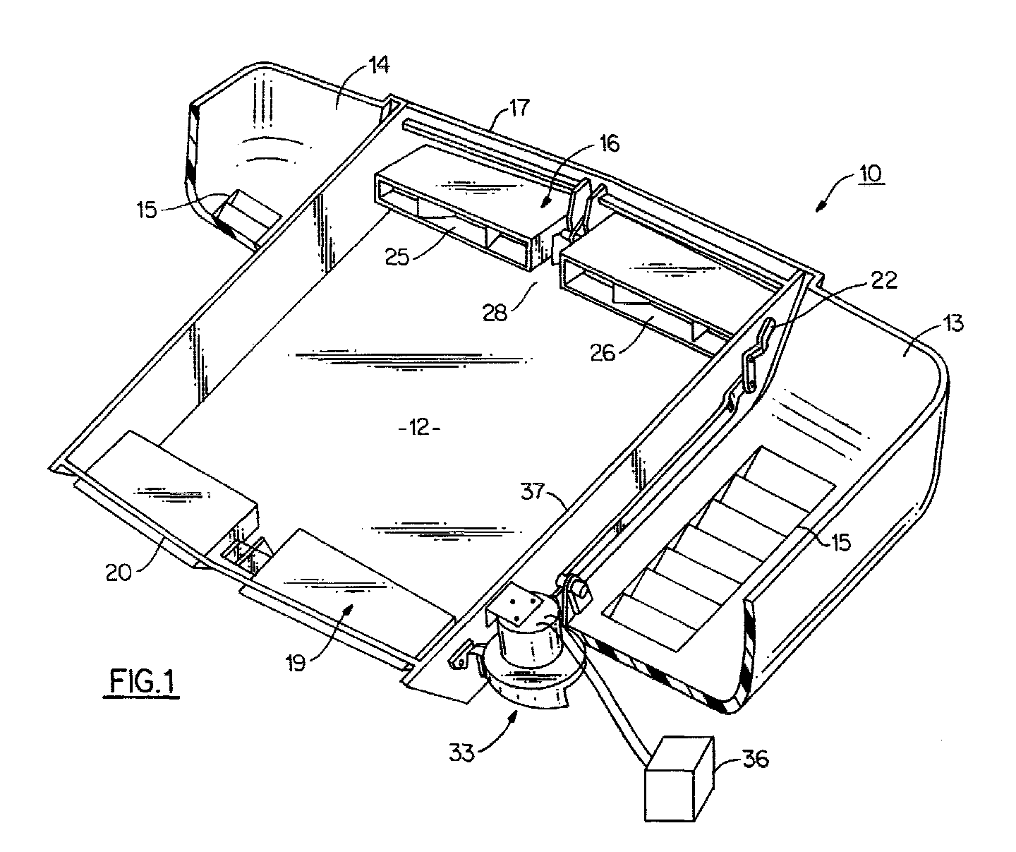
- a ceiling grille that embodies the teachings of the present invention.
- the grille is suitable for installation in a motor vehicle such as a recreational vehicle (RV) or the like to return air from the passenger compartment to a roof top air conditioning unit (not shown) and distribute comfort air from the air conditioning unit back into the passenger compartment.
- the grille 10 includes a central comfort air plenum 12 and two side return air channels 13 and 14.
- the side return air compartments contain floor installed louvers 15 and are each connected to the air intake of the air conditioning unit by any suitable means.
- Air from the passenger compartment is drawn through the air return channels into the air conditioning unit where it is passed through an evaporator coil to 5 condition the return air.
- the conditioned air is then discharged into the comfort air plenum.
- the plenum is equipped with a front air distributor 16 located in the front wall 17 of the plenum and a rear air distributor 19 located in the rear wall 20 of the plenum.
- Each distributor is mounted for rotation in the front and rear walls of the housing by axially aligned end shafts 22 so that the distributors can be turned between a first position to direct air generally in an upward direction and a second position to direct air in a generally downward direction.
- Each distributor contains a pair of ducts 25 and 26 that are separated by a central channel 28 that contains a horizontally disposed pinion 29(Fig. 5).
- a torsion spring 30 is wound in a loaded condition about the pinion and is arranged to rotate the distributor into the upwardly tilted position.
- the comfort air distributors are automatically positioned to provide for more efficient distribution of comfort air throughout the passenger compartment.
- Both comfort air distributors are positioned by means of a cam element generally referenced 33 that is mounted for rotation upon the shaft 34 of a stepper motor 35 mounted in the side wall 37 of the plenum.
- the motor is remotely operated by a controller 36 that is capable of stepping the motor and the cam in either direction.
- a pair of cam followers 38 and 39 ride in contact with the profiled cam face 40 of the cam.
- the first cam follower 38 includes an arm 41 mounted upon a hub 42 which, in turn, is pivotally mounted upon a shaft 43.
- a second arm 44 is mounted upon the hub 42 and is angularly offset from arm 41 so that the 5 second arm 44 rocks back and forth about the shaft as the cam follower rides over the cam face.
- a dowel 48 (Fig. 3) extends horizontally from the distal end of the second arm 43 as best shown in Fig. 3.
- a rocker arm 49 is attached to one of the end shafts 22 of the rear comfort air deflector 19 and the distal end of the rocker arm rides in contact with the dowel 48. Under the influence of the torsion spring 30, the rocker arm is held in biasing contact against the dowel which, in turn, pressures the cam follower 38 into contact against the cam face of the cam element. As can be seen, under this biasing action, the motion of the cam face is translated efficiently through the coacting members to the rear comfort air deflector 19 to rotate the deflector to a position prescribed by the cam profile.
- the second cam follower 39 in the form of an arm, is secured to a pivot pin 50 that is horizontally supported in a stanchion 51.
- a link 53 is also secured at one end for rotation with the pivot pin so that it turns with the cam follower 39.
- the opposite end of the link is rotationally secured to the proximal end of an elongated, horizontally disposed connecting bar 55.
- the distal end of the bar is similarly secured to a crank 57.
- the crank contains a lever arm 58 and an angularly offset actuator arm 59, both of which are integrally attached to a hub 60.
- the hub in turn, is rotatably supported upon a stub shaft 62 so that the crank rotates about the stub shaft.
- the front comfort air deflector 18 is rotatably mounted in the front wall of the housing in the same manner as the rear comfort air deflector 19 by end shafts 22.
- a rocker arm 62 is secured in one of the front comfort air deflector end shafts.
- the distal end of the rocker arm contains a pin 63 that rides in contact with the actuator arm 59 of the crank.
- the torsion spring associated with the front comfort air deflector acts upon the deflector to turn the deflector in a counterclockwise direction, as seen in Fig. 2. This, in turn, biases the rocker arm into contact with the crank so that the rocker arm moves in response to the rotational movement of the crank.
- the rotational positioning of the front comfort air deflector is controlled by the cam 33 acting 5 through the above described linkage.
- the cam face is profiled to coordinate the positioning of the two deflectors so that the comfort air is most efficiently distributed throughout the passenger compartment throughout the range prescribed by the cam.
- the range typically extends between a first upwardly tilted position wherein air is directed toward the ceiling and a downwardly directed position wherein air is directed away from the ceiling.
- Fig. 5 the front comfort air deflector is shown in a fully closed and latched position.
- Each deflector can be manually turned to this position in the event passengers in the vehicle want to manually close down one or both deflectors.
- the deflectors are equipped with a latching mechanism, generally referenced 80 for securing the detector in the closed position.
- the latching mechanism includes a rod 81 attached to the deflector that has an expanded head 82 at its distal end. The head of the rod is arranged to be engaged by a spring clamp 83 when the deflector is turned to the fully closed position to lock the deflector in this position.
- the rocker arm associated with the deflector is lifted away from the cam associated linkage thereby removing the deflector from the cam.
Landscapes
- Physics & Mathematics (AREA)
- Thermal Sciences (AREA)
- Engineering & Computer Science (AREA)
- Mechanical Engineering (AREA)
- Air-Conditioning For Vehicles (AREA)
- Air-Flow Control Members (AREA)
Abstract
Description
Claims (6)
- A ceiling mounted grille for a motor vehicle for directing conditioned air from an air conditioning unit mounted upon the roof of the vehicle into the passenger compartment of the vehicle, wherein said grille is characterized by:a plenum for receiving conditioned air for the air conditioning unit, said plenum having a front wall, a rear wall and opposed side walls,a front deflector vane rotatably mounted in the front wall of said plenum,a rear deflector vane rotatably mounted in the rear wall of the plenum,a first rocker arm connected to the front deflector vane and a second rocker arm connected to said rear deflector vane, said rocker arm being arranged to rotate said deflector vanes between an open position and a closed position,a cam having a profiled camming face thereon,a first cam follower arranged to ride in contact with said camming face and a second cam follower also arranged to ride in contact with said camming face,means for connecting said first rocker arm to said cam follower and said second rocker arm to said second cam follower for selectively positioning the deflection vane in response to the positioning of the cam, anddrive means for positioning said cam.
- The grille of claim 1 that further includes biasing means for holding the cam follower in contact with the cam face.
- The grille of claim 2 wherein said biasing means is a torsion spring acting upon each deflector vane for rotating the deflector bane in a direction such that each cam followers are urged against the cam face through the first and second rocker arms and said connecting means.
- The grille of claim 1 wherein said drive means is a stepper motor.
- The grille of claim 1 wherein said second cam follower is pivotally mounted adjacent to said cam and contains a cam follower arm that rides in contact with said cam face and a pivot arm and said connecting means further includes an elongated link arm connected at one end to said pivot arm and at the opposite end to a crank that is arranged to move the second rocker arm.
- The grille of claim 3 wherein each deflector vane includes a latch means for holding the deflector vane in a closed position so that the spring biasing force of the torsion spring is released form the associated cam follower.
Applications Claiming Priority (2)
| Application Number | Priority Date | Filing Date | Title |
|---|---|---|---|
| US580072 | 2000-05-30 | ||
| US09/580,072 US6302780B1 (en) | 2000-05-30 | 2000-05-30 | Ceiling grille for rooftop air conditioner unit |
Publications (3)
| Publication Number | Publication Date |
|---|---|
| EP1160519A2 true EP1160519A2 (en) | 2001-12-05 |
| EP1160519A3 EP1160519A3 (en) | 2003-01-29 |
| EP1160519B1 EP1160519B1 (en) | 2005-08-17 |
Family
ID=24319554
Family Applications (1)
| Application Number | Title | Priority Date | Filing Date |
|---|---|---|---|
| EP01201962A Expired - Lifetime EP1160519B1 (en) | 2000-05-30 | 2001-05-25 | Ceiling grille for rooftop air conditioner unit |
Country Status (5)
| Country | Link |
|---|---|
| US (1) | US6302780B1 (en) |
| EP (1) | EP1160519B1 (en) |
| AU (1) | AU766615B2 (en) |
| CA (1) | CA2345865C (en) |
| DE (1) | DE60112655T2 (en) |
Families Citing this family (29)
| Publication number | Priority date | Publication date | Assignee | Title |
|---|---|---|---|---|
| AU2003280658A1 (en) * | 2002-10-31 | 2004-05-25 | Daikin Industries, Ltd. | Indoor apparatus for air conditioner |
| US20040226556A1 (en) | 2003-05-13 | 2004-11-18 | Deem Mark E. | Apparatus for treating asthma using neurotoxin |
| US12433837B2 (en) | 2005-07-22 | 2025-10-07 | The Foundry, Llc | Systems and methods for delivery of a therapeutic agent |
| EP1906923B1 (en) | 2005-07-22 | 2018-01-24 | The Foundry, LLC | Systems and methods for delivery of a therapeutic agent |
| US8535127B2 (en) * | 2006-11-22 | 2013-09-17 | Dometic Corporation | Air distribution apparatus |
| KR101045380B1 (en) * | 2008-12-23 | 2011-06-30 | 엘지전자 주식회사 | Ceiling air conditioners |
| US9975405B2 (en) | 2013-03-14 | 2018-05-22 | Dometic Corporation | Modular air grill assembly |
| US10166840B2 (en) * | 2015-06-03 | 2019-01-01 | Mahindra Vehicle Manufacturers Limited | Auxiliary air distribution system for use in a vehicle |
| USD850609S1 (en) | 2015-10-15 | 2019-06-04 | Dometic Sweden Ab | Modular air grill |
| AU2017200186A1 (en) | 2016-01-16 | 2017-08-03 | Dometic Sweden Ab | Parking cooler |
| USD817466S1 (en) | 2016-01-19 | 2018-05-08 | Dometic Sweden Ab | Air shroud assembly |
| AU367405S (en) | 2016-02-12 | 2016-03-01 | Dometic Sweden Ab | Recreational vehicle air-conditioning unit |
| AU2017222697B2 (en) | 2016-02-22 | 2022-01-20 | Dometic Sweden Ab | Vehicle air conditioner |
| AU2017222698B2 (en) | 2016-02-22 | 2022-06-16 | Dometic Sweden Ab | Air-conditioner control |
| AU201612249S (en) | 2016-04-28 | 2016-05-31 | Dometic Sweden Ab | Air-conditioning unit |
| AU201712794S (en) | 2016-11-23 | 2017-05-23 | Dometic Sweden Ab | Ventilation and air conditioning apparatus |
| USD915569S1 (en) | 2017-02-17 | 2021-04-06 | Dometic Sweden Ab | Shroud assembly |
| US10594078B2 (en) * | 2017-04-21 | 2020-03-17 | Hewlett Packard Enterprise Development Lp | Rocker-arm assemblies with connectable cable |
| AU2018366469B2 (en) | 2017-11-16 | 2024-09-12 | Dometic Sweden Ab | Air conditioning apparatus for recreational vehicles |
| CN112055800B (en) | 2018-04-23 | 2023-02-17 | 多美达瑞典有限公司 | Damped Portable Compressor |
| USD940289S1 (en) | 2018-04-30 | 2022-01-04 | Dometic Sweden Ab | Mobile air conditioner |
| USD905217S1 (en) | 2018-09-05 | 2020-12-15 | Dometic Sweden Ab | Air conditioning apparatus |
| US11951798B2 (en) | 2019-03-18 | 2024-04-09 | Dometic Sweden Ab | Mobile air conditioner |
| US11987093B2 (en) | 2019-03-18 | 2024-05-21 | Dometic Sweden Ab | Mobile air conditioner |
| DE102019212946B4 (en) | 2019-08-28 | 2023-03-30 | Dometic Sweden Ab | Component of an air conditioning or window system for a recreational vehicle |
| DE102019212949B4 (en) | 2019-08-28 | 2023-04-27 | Dometic Sweden Ab | Modular climate control system for a recreational vehicle having an air conditioner and a window, and method of replacing the window with the air conditioner of the modular climate control system |
| US12589627B2 (en) | 2019-08-28 | 2026-03-31 | Dometic Sweden Ab | Structure for moving wire from exterior to interior of a vehicle |
| IT201900019193A1 (en) | 2019-10-17 | 2021-04-17 | Dometic Sweden Ab | AIR CONDITIONING APPARATUS FOR RECREATIONAL VEHICLES |
| USD1027143S1 (en) | 2021-07-12 | 2024-05-14 | Dometic Sweden Ab | Housing shroud for an air conditioner |
Family Cites Families (7)
| Publication number | Priority date | Publication date | Assignee | Title |
|---|---|---|---|---|
| US3868896A (en) * | 1973-03-28 | 1975-03-04 | Massey Ferguson Inc | Vehicle cab enclosure with ventilation means |
| US3937133A (en) * | 1974-09-27 | 1976-02-10 | Mannie Bertin | Outlets for conditioned air and mounting frames therefor |
| US4417687A (en) * | 1982-06-07 | 1983-11-29 | Grant Willie T | Multi-blade automatic air register damper |
| US4709623A (en) * | 1986-08-22 | 1987-12-01 | Nordyne, Inc. | Ceiling distributor duct assembly for rooftop air conditioners |
| US5501634A (en) * | 1994-10-31 | 1996-03-26 | Wilder; Timothy S. | Air conditioner cover assembly |
| KR100210085B1 (en) * | 1996-03-21 | 1999-07-15 | 윤종용 | Wind direction controller of air conditioner |
| US6196914B1 (en) * | 1999-07-12 | 2001-03-06 | Carrier Corporation | Ceiling grille for air conditioner of recreational vehicle |
-
2000
- 2000-05-30 US US09/580,072 patent/US6302780B1/en not_active Expired - Fee Related
-
2001
- 2001-05-01 CA CA002345865A patent/CA2345865C/en not_active Expired - Fee Related
- 2001-05-25 DE DE60112655T patent/DE60112655T2/en not_active Expired - Lifetime
- 2001-05-25 EP EP01201962A patent/EP1160519B1/en not_active Expired - Lifetime
- 2001-05-28 AU AU48066/01A patent/AU766615B2/en not_active Ceased
Also Published As
| Publication number | Publication date |
|---|---|
| AU766615B2 (en) | 2003-10-23 |
| CA2345865C (en) | 2004-02-24 |
| DE60112655D1 (en) | 2005-09-22 |
| AU4806601A (en) | 2001-12-06 |
| US6302780B1 (en) | 2001-10-16 |
| EP1160519A3 (en) | 2003-01-29 |
| CA2345865A1 (en) | 2001-11-30 |
| EP1160519B1 (en) | 2005-08-17 |
| DE60112655T2 (en) | 2006-05-18 |
Similar Documents
| Publication | Publication Date | Title |
|---|---|---|
| EP1160519B1 (en) | Ceiling grille for rooftop air conditioner unit | |
| US6196914B1 (en) | Ceiling grille for air conditioner of recreational vehicle | |
| JP6138427B2 (en) | Heat pump air conditioning system for vehicles | |
| US7029390B2 (en) | Air vent for vehicle air ducting | |
| EP0058416A2 (en) | Air conditioning system | |
| US5569076A (en) | Oscillation fixed grille outlet | |
| EP1361088A1 (en) | Distributor valve with air deflector vanes for a heating and ventilating system of a motor vehicle | |
| EP1086839A1 (en) | Air mix damper device and vehicle air conditioner | |
| EP1364819B1 (en) | Motorized damper door for vehicle air duct | |
| GB2347207A (en) | Air conditioning apparatus having a heater with a hot water flow valve and a bypass passage with a door | |
| JP2003341338A (en) | Vehicle air conditioner | |
| US5203737A (en) | Multiple entry air passage | |
| KR100366570B1 (en) | Evaporator mounted structure for cooling system of automobile | |
| JP2006056451A (en) | Air conditioner for vehicles | |
| JPS6310326Y2 (en) | ||
| US6116329A (en) | Heating or air-conditioning system | |
| KR20150124243A (en) | An intake device for air conditioner of vehicles | |
| JP2537137Y2 (en) | Air volume control valve | |
| KR101492149B1 (en) | Cam and driving unit assembly for air conditioner in vehicles | |
| JP4192317B2 (en) | Air conditioner for vehicles | |
| JPH05301515A (en) | Air-conditioning device for vehicle | |
| JPH11334341A (en) | Vehicle air conditioner | |
| KR20260065651A (en) | a hidden air vent with ball-joint | |
| KR100552714B1 (en) | Structure of Ventilation Duct for Automotive Air Conditioning System | |
| JPS6313042Y2 (en) |
Legal Events
| Date | Code | Title | Description |
|---|---|---|---|
| PUAI | Public reference made under article 153(3) epc to a published international application that has entered the european phase |
Free format text: ORIGINAL CODE: 0009012 |
|
| AK | Designated contracting states |
Kind code of ref document: A2 Designated state(s): AT BE CH CY DE DK ES FI FR GB GR IE IT LI LU MC NL PT SE TR |
|
| AX | Request for extension of the european patent |
Free format text: AL;LT;LV;MK;RO;SI |
|
| PUAL | Search report despatched |
Free format text: ORIGINAL CODE: 0009013 |
|
| AK | Designated contracting states |
Designated state(s): AT BE CH CY DE DK ES FI FR GB GR IE IT LI LU MC NL PT SE TR |
|
| AX | Request for extension of the european patent |
Extension state: AL LT LV MK RO SI |
|
| RIC1 | Information provided on ipc code assigned before grant |
Ipc: 7F 24F 13/06 A Ipc: 7B 60H 1/00 B Ipc: 7B 60H 1/24 B |
|
| AKX | Designation fees paid |
Designated state(s): CH DE GB LI SE |
|
| 17P | Request for examination filed |
Effective date: 20031007 |
|
| GRAP | Despatch of communication of intention to grant a patent |
Free format text: ORIGINAL CODE: EPIDOSNIGR1 |
|
| GRAS | Grant fee paid |
Free format text: ORIGINAL CODE: EPIDOSNIGR3 |
|
| GRAA | (expected) grant |
Free format text: ORIGINAL CODE: 0009210 |
|
| AK | Designated contracting states |
Kind code of ref document: B1 Designated state(s): CH DE GB LI SE |
|
| REG | Reference to a national code |
Ref country code: GB Ref legal event code: FG4D |
|
| REG | Reference to a national code |
Ref country code: CH Ref legal event code: EP |
|
| REG | Reference to a national code |
Ref country code: CH Ref legal event code: NV Representative=s name: BRAUNPAT BRAUN EDER AG |
|
| REF | Corresponds to: |
Ref document number: 60112655 Country of ref document: DE Date of ref document: 20050922 Kind code of ref document: P |
|
| REG | Reference to a national code |
Ref country code: SE Ref legal event code: TRGR |
|
| PLBE | No opposition filed within time limit |
Free format text: ORIGINAL CODE: 0009261 |
|
| STAA | Information on the status of an ep patent application or granted ep patent |
Free format text: STATUS: NO OPPOSITION FILED WITHIN TIME LIMIT |
|
| 26N | No opposition filed |
Effective date: 20060518 |
|
| PGFP | Annual fee paid to national office [announced via postgrant information from national office to epo] |
Ref country code: GB Payment date: 20100329 Year of fee payment: 10 |
|
| PGFP | Annual fee paid to national office [announced via postgrant information from national office to epo] |
Ref country code: DE Payment date: 20100519 Year of fee payment: 10 |
|
| PGFP | Annual fee paid to national office [announced via postgrant information from national office to epo] |
Ref country code: CH Payment date: 20100514 Year of fee payment: 10 |
|
| PGFP | Annual fee paid to national office [announced via postgrant information from national office to epo] |
Ref country code: SE Payment date: 20100510 Year of fee payment: 10 |
|
| REG | Reference to a national code |
Ref country code: DE Ref legal event code: R119 Ref document number: 60112655 Country of ref document: DE |
|
| REG | Reference to a national code |
Ref country code: DE Ref legal event code: R119 Ref document number: 60112655 Country of ref document: DE |
|
| REG | Reference to a national code |
Ref country code: CH Ref legal event code: PL |
|
| REG | Reference to a national code |
Ref country code: SE Ref legal event code: EUG |
|
| GBPC | Gb: european patent ceased through non-payment of renewal fee |
Effective date: 20110525 |
|
| PG25 | Lapsed in a contracting state [announced via postgrant information from national office to epo] |
Ref country code: LI Free format text: LAPSE BECAUSE OF NON-PAYMENT OF DUE FEES Effective date: 20110531 Ref country code: CH Free format text: LAPSE BECAUSE OF NON-PAYMENT OF DUE FEES Effective date: 20110531 |
|
| PG25 | Lapsed in a contracting state [announced via postgrant information from national office to epo] |
Ref country code: GB Free format text: LAPSE BECAUSE OF NON-PAYMENT OF DUE FEES Effective date: 20110525 |
|
| PG25 | Lapsed in a contracting state [announced via postgrant information from national office to epo] |
Ref country code: SE Free format text: LAPSE BECAUSE OF NON-PAYMENT OF DUE FEES Effective date: 20110526 |
|
| PG25 | Lapsed in a contracting state [announced via postgrant information from national office to epo] |
Ref country code: DE Free format text: LAPSE BECAUSE OF NON-PAYMENT OF DUE FEES Effective date: 20111130 |
|
| REG | Reference to a national code |
Ref country code: DE Ref legal event code: R082 Ref document number: 60112655 Country of ref document: DE Representative=s name: SCHMITT-NILSON SCHRAUD WAIBEL WOHLFROM PATENTA, DE |