EP1160423A2 - Valve control system for electromagnetic valve - Google Patents
Valve control system for electromagnetic valve Download PDFInfo
- Publication number
- EP1160423A2 EP1160423A2 EP01113316A EP01113316A EP1160423A2 EP 1160423 A2 EP1160423 A2 EP 1160423A2 EP 01113316 A EP01113316 A EP 01113316A EP 01113316 A EP01113316 A EP 01113316A EP 1160423 A2 EP1160423 A2 EP 1160423A2
- Authority
- EP
- European Patent Office
- Prior art keywords
- movable member
- valve
- electromagnets
- controller
- control
- Prior art date
- Legal status (The legal status is an assumption and is not a legal conclusion. Google has not performed a legal analysis and makes no representation as to the accuracy of the status listed.)
- Granted
Links
- 230000010355 oscillation Effects 0.000 claims abstract description 11
- 238000000034 method Methods 0.000 claims description 7
- 238000002485 combustion reaction Methods 0.000 claims description 3
- 239000010687 lubricating oil Substances 0.000 claims 2
- 230000001050 lubricating effect Effects 0.000 claims 1
- 239000002826 coolant Substances 0.000 description 15
- 230000007935 neutral effect Effects 0.000 description 5
- 238000010586 diagram Methods 0.000 description 3
- 238000006073 displacement reaction Methods 0.000 description 3
- 238000005461 lubrication Methods 0.000 description 3
- 238000012937 correction Methods 0.000 description 2
- 238000013461 design Methods 0.000 description 2
- 238000012545 processing Methods 0.000 description 2
- 101001064774 Homo sapiens Peroxidasin-like protein Proteins 0.000 description 1
- 101001038163 Homo sapiens Sperm protamine P1 Proteins 0.000 description 1
- 102100031894 Peroxidasin-like protein Human genes 0.000 description 1
- 238000013459 approach Methods 0.000 description 1
- 238000013016 damping Methods 0.000 description 1
- 238000005265 energy consumption Methods 0.000 description 1
- 238000002474 experimental method Methods 0.000 description 1
- 239000000696 magnetic material Substances 0.000 description 1
- 238000004519 manufacturing process Methods 0.000 description 1
- 238000012986 modification Methods 0.000 description 1
- 230000004048 modification Effects 0.000 description 1
Images


Classifications
-
- F—MECHANICAL ENGINEERING; LIGHTING; HEATING; WEAPONS; BLASTING
- F01—MACHINES OR ENGINES IN GENERAL; ENGINE PLANTS IN GENERAL; STEAM ENGINES
- F01L—CYCLICALLY OPERATING VALVES FOR MACHINES OR ENGINES
- F01L9/00—Valve-gear or valve arrangements actuated non-mechanically
- F01L9/20—Valve-gear or valve arrangements actuated non-mechanically by electric means
Definitions
- the present invention relates to a control system for controlling an electromagnetically operated valve, and more particularly to an electromagnetic valve control system which is capable of executing a soft landing of a movable member onto an electromagnet in a valve open/close control.
- Such soft landing in this system is achieved by temporally switching off the electromagnet during a period between a switch-on moment of the electromagnet and the landing moment of the movable member. Further, in order to realize a further accurate landing control of an electromagnetic valve unit including a valve and an electromagnetic actuator, there has been proposed a control method employing a characteristic representative of a vibration system of the electromagnetic valve unit.
- the characteristic of the vibration system of the controlled electromagnetic valve unit is varied according to an operating condition.
- a friction in the electromagnetic valve unit is largely affected by a temperature since the friction largely depends on a characteristic of rubricating oil whose viscosity is varied according to the change of temperature. Therefore, it is difficult to stably execute a required landing control only by a preset characteristic representative quantity.
- An aspect of the present invention resides in a valve control system which comprises an electromagnetic valve unit and a controller.
- the electromagnetic valve unit comprises a valve, a pair of electromagnets arranged in spaced relationship from one another in axial alignment with the valve so as to form a space, a movable member axially movably disposed in the space between the electromagnets and interlocked with the valve, a pair of springs biasing the movable member so as to locate the movable member at an intermediate portion of the space when both of the electromagnets are de-energized.
- the controller is connected to the electromagnetic valve unit and executes an initialization control for moving the movable member to a start position by repeatingly energizing the electromagnets according to a natural frequency of a vibration system of the electromagnetic valve unit.
- the controller detects amplitudes of oscillation of the movable member during the initialization control, calculates an increase-degree of the detected amplitudes, and estimates a friction quantity of the vibration system on the basis of the calculated increase-degree.
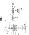
- FIGs. 1 to 11 there is shown an embodiment of a control system for electromagnetically operated engine valves in accordance with the present invention.
- the control system is adapted to control intake and exhaust valves of an internal combustion engine for an automotive vehicle.
- Four valve units 100 are provided to each cylinder of the engine. Two of valve units 100 perform as intake valves, and the other two of valve units 100 perform as exhaust valves. More specifically, by each cylinder of the engine, two intake ports communicated with an intake passage and two exhaust ports communicated with an exhaust passage are formed in a cylinder head 1. In order to facilitate the explanation the structure of the valve units 100, one of the valve units 100 will be discussed.
- a valve 3 of each valve unit 100 is installed to one port 2 of intake and exhaust ports.
- Valve 3 penetrates a lower wall of a housing 12, and is reciprocally movable while being supported by cylinder head 1.
- a retainer 4 is fixed to a top end portion of valve 3.
- a valve closing spring 5 is installed between retainer 4 and a wall of cylinder head 1 faced with retainer 4, and biases valve 3 into a valve closing direction.
- a plate-like movable member 6 made of soft magnetic material is integrally connected to a guide shaft 7.
- a lower tip end of guide shaft 7 is in contact with an upper end of valve 3.
- a retainer 8 is fixed to an upper portion of guide shaft 7.
- a valve opening spring 9 is installed between retainer 8 and an upper wall of housing 12.
- Valve opening spring 9 biases movable member 6 integral with guide shaft 7 into the valve opening direction, and therefore valve 3 is biased into the valve opening direction by valve opening spring 9 through guide shaft 7. Accordingly, valve 3 and movable member 6 are integrally movable in reciprocating motion.
- valve closing and opening springs 5 and 9 bias movable member 6 at a neutral position shown in Fig. 1.
- a valve opening electromagnet 10 is disposed below movable member 6 while having a predetermined clearance from movable member 6, and a valve closing electromagnet 11 is disposed above movable member 6 while having a predetermined clearance from movable member 6. Therefore, movable member 6 is movably disposed in a space between valve opening and closing electromagnets 10 and 11. Both valve opening and closing electromagnets 10 and 11 have guide holes respectively, and guide shaft 7 is reciprocatingly supported to these guide holes.
- the neutral position of movable member 6 is located at a generally center (intermediate) position between valve opening and closing electromagnets 10 and 11.
- a position sensor 13 is installed in housing 12 and detects a position of movable member 6 in the axial direction.
- a laser displacement meter is employed as position sensor 13.
- a controller 21 of the control system receives a valve opening/closing command from an engine control unit 22 and outputs an energizing signal to a drive circuit 23 on the basis of the received valve opening/closing command to energize valve opening electromagnet 10 or valve closing electromagnet 11.
- Drive circuit 23 supplies electric current from an electric source (not-shown) to each electromagnet 10, 11 so as to apply suitable electromagnetic force to movable member 6.
- controller 21 receives a temperature signal indicative of a lubrication oil temperature from a temperature sensor 14 and a current i to be supplied to each electromagnet 10, 11 from drive circuit 23.
- a coolant temperature signal Tw indicative of an engine coolant temperature is inputted to controller 21 as a temperature corresponding to a lubrication oil temperature.
- valve unit 100 Next, the manner of operation of valve unit 100 will be discussed.
- valve closing and opening springs 5 and 9 have been designed so that movable member 6 is positioned at the neutral position due to the biasing forces of springs 5 and 9 when both electromagnets 10 and 11 are de-energized.
- an initialization control for positioning movable member 6 at a seated (landing) position on valve closing electromagnet 11 is executed in order to decrease energy consumption and to lower a production cost of a current supply circuit of electromagnets 10 and 11.
- valve unit 100 is represented as a mass-spring vibration system which is constituted by springs 5 and 9 and movable parts including valve 3, movable member 6 and guide shaft 7.
- valve opening and closing electromagnets 10 and 11 By alternatively switching on valve opening and closing electromagnets 10 and 11 at a cycle corresponding to this natural frequency f 0 , the mass-spring vibration system generates a resonance and achieves the initialization control (hereinafter, this initialization is called "resonance initialization").
- valve closing electromagnet 11 is first de-energized.
- movable member 6 is basically displaced downward due to the forces of springs 5 and 9.
- Movable parts of valve unit 100 generates energy loss due to some friction based on a viscosity of lubrication oil.
- valve opening electromagnet 10 is energized during an opening process of movable member 6.
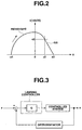
- a graph of Fig. 2 shows a locus of movable member 6.
- a horizontal axis represents a position z of movable member 6 when the neutral position of movable member 6 is set at an origin point
- a vertical axis represents a velocity v of movable member 6 at the position z.
- velocity v of movable member 6 after starting energizing valve opening electromagnet 10 is controlled at a target velocity r according to the position z by means of a feedback control shown in Fig. 3.
- controller 21 detects velocity v of movable member 6 and outputs the energizing command so that the detected velocity v follows up the target velocity r.
- energizing valve opening electromagnet 10 through drive circuit 23 according to the energizing current, it becomes possible to land movable member 6 on valve opening electromagnet 10 at a predetermined velocity such as 0.1 (m/s) or less. Further, it becomes possible to stop movable member 6 at a position where movable member 6 has a predetermined gap with respect to valve opening electromagnet 10 and to maintain movable member 6 at the gapped position until the next closing operation is executed.
- valve unit 100 Although only the operation of valve unit 100 during the valve opening period has been discussed hereinabove, the operation during the valve closing period is also executed as is similar to that during the valve opening period. Therefore, the explanation of the operation during the valve closing period is omitted herein.
- valve control system it is possible to estimate friction c from a waveform of movable member 6 during the resonance initialization and to reflect the estimate friction c in the landing control.
- Fig. 4 shows a block diagram of controller 21 of the valve control system according to the present invention.
- An initial-period friction estimating section 31 of controller 21 reads position z during the resonance initialization control and detects an increase-degree ⁇ of an amplitude of the initialization oscillation of movable member 6.
- Initial-period friction estimating section 31 estimates friction c at the present temperature on the basis of the detected increase-degree ⁇ and an increase-friction map 32 previously provided in controller 21.
- Increase-friction map 32 represents a relationship between the increase-degree ⁇ and the friction c.
- Controller 21 stores the estimated friction c with the coolant temperature Tw at the estimated period in the friction-temperature map 33 in the form of a temperature-friction relationship.
- the estimated friction c at the detected coolant temperature Tw is stored instead of the previously stored friction data.
- a normal-operation friction estimating section 34 of controller 21 estimates the friction c at the present temperature on the basis of the detected coolant temperature Tw and with reference to the temperature-friction map 33.
- friction c is interpolated from the stored two temperature-friction data adjacent to the detected coolant temperature.
- a control parameter setting section 35 of controller sets an optimum control parameter PRM on the basis of friction c estimated at initial-period fiction estimating section 31 or normal-operation friction estimating section 34.
- the control gain (feedback gain) G of the landing controller shown in Fig. 3 may be varied according to friction c.
- a main processing section 36 outputs energizing commands to drive circuit 23 for energizing valve opening electromagnet 10 and valve closing electromagnet 11, respectively, upon taking account of the estimated friction c and the set control parameter PRM when main processing section 36 receives valve opening/closing command from an engine control unit 22.
- controller 21 will be discussed with reference to a flowchart of Fig. 5, which shows a resonance initialization control routine executed at the start of valve unit 100. This flowchart executes the resonance initialization control and the estimation of friction c.
- controller 21 reads the position z of movable member 6.
- controller 21 decides whether the resonance initialization has been completed or not. In this embodiment, controller decides whether movable member 6 reaches the initial position in order to decide the completion of the resonance initialization.
- the routine proceeds to step S3.
- the decision at step S2 is affirmative, the routine proceeds to step S5.
- controller 21 commands drive circuit 23 to alternatively switch on valve opening and closing electromagnets 10 and 11 so as to increase the amplitude of the oscillation of movable member 6.
- controller 21 stores a present position z.
- controller 21 calculates the increase-degree ⁇ of the amplitude of movable member 6 on the basis of the position information z stored in controller 21.
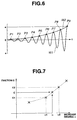
- controller 21 accumulates the position z of movable member during the resonance initialization by repeatingly executing step S4 and forms a waveform W1 representative of an oscillation of movable member 6 during the resonance initialization as shown in Fig. 6.
- Controller 21 obtains peak points P1 to P9 of the respective cycles from the waveform W1 and obtains the increase-degree ⁇ from a curve W2 obtained by connecting the peak points P1 to P9 as shown in Fig. 6.
- the increase rate of curve W2 may be treated as the increase-degree ⁇ .
- the increase-degree ⁇ is large, the resonance initialization is rapidly achieved. Therefore, in this rapidly achieved condition, controller 21 estimates that friction c is small.
- the increase-degree ⁇ is small, the resonance initialization is not rapidly achieved and takes a relatively long time. Accordingly, in this late condition, controller 21 estimates that friction c is large.
- the increase rate in this equation (2) is represented by a coefficient b of the equation (2).
- a (1 - e -bt ) At
- an amplitude at time t is At
- a maximum amplitude in this vibration system is a.
- Steps S1 and S4 constitutes initialization amplitude detecting means, and step S5 constitutes amplitude increase-degree calculating means.
- controller 21 estimates friction c on the basis of the calculated increase-degree ⁇ and the increase-fiction map 32.
- a plurality of fictions c1 to cn corresponding to a plurality of increase-degrees ⁇ 1 to ⁇ n have been previously measured and stored as increase-friction map 32.
- two frictions c1 and c2 corresponding to increase-degrees ⁇ 1 and ⁇ 2 the explanation will be made with reference to a graph of Fig. 7.
- controller 21 sets an optimum control parameter PRM with respect to the estimated friction c.
- the relationship between optimum control parameters PRM1 to PRMn, frictions c1 to cn has been previously obtained by experiments and stored in a map of controller 21. Accordingly, controller 21 obtains the control parameter PRM employed in the actual control from the map and on the basis of the estimated friction c.
- This step S7 constitutes a control parameter setting means.
- the control parameter PRM set at step S7 corresponds with a control gain G employed in the energizing control for electromagnets 10 and 11. If the velocity v of movable member 6 is estimated from an observer of the landing control, friction c may be directly reflected in the design of the observer.
- controller 21 reads coolant temperature Tw.
- controller 21 stores the estimated friction c as a relationship to the coolant temperature Tw and updates the temperature-friction map 33 by each execution of the resonance initialization.
- the temperature-friction map 33 at an initial condition has stored only the coordinate axes coolant temperature Tw and friction c, and then gradually increases the information by each resonance initialization. It is preferable to update the map 33 with the new data when coolant temperature Tw of the new data whose corresponding coolant temperature Tw has already been stored is obtained. By this updating operation, the map 33 is gradually perfected, particularly fulfills the data in an ordinary temperature during the resonance initialization.
- This step S9 constitutes a friction quantity storing means.
- controller 21 reads the valve opening/closing command for each valve unit 100 for each of intake and exhaust valves.
- controller 21 decides whether the read command is the valve opening command or not. When the decision at step S12 is affirmative, the routine proceeds to step S13. When the decision at step S12 is negative, the routine proceeds to step S15.
- controller 21 commands driver circuit 23 to de-energize the valve closing electromagnet (VCE) 11.
- controller 21 commands drive circuit 23 to energize the valve opening electromagnet (VOE) 10 and to execute the landing control. That is, the routine jumps to the landing control routine shown by a flowchart of Fig. 10. After the execution of the landing control routine as to valve opening electromagnet 10, the routine proceeds to step S15.
- the landing control routine will be discussed later.
- controller 21 decides whether the received commands include the valve close command or not.
- the routine proceeds to step S16.
- the routine proceeds to a return step.
- controller 21 commands driver circuit 23 to de-energize the valve opening electromagnet (VOE) 10.
- controller 21 commands drive circuit 23 to energize the valve closing electromagnet (VCE) 11 and to execute the landing control of the valve closing electromagnet 11. That is, the routine jumps to the landing control routine shown by the flowchart of Fig. 10. After the execution of the landing control routine as to valve closing electromagnet 11, the routine proceeds to the return block.
- VCE valve closing electromagnet
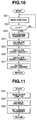
- this routine is executed as a subroutine at steps S14 and S17 of Fig. 9, separately.
- controller 21 reads the position z of movable member 6.
- controller 21 decides whether the read position z is greater than or equal to the value z2 or not. That is, controller 21 decides whether or not movable member 6 is moved to a position where the electromagnetic force of valve opening electromagnet 10 (or valve closing electromagnet 11) affects movable member 6 as shown in Fig. 2.
- the routine returns to step S21. That is, steps S21 and S22 are repeated until the decision at step S22 becomes affirmative.
- the routine proceeds to step S23.
- controller 21 executes the control parameter setting control to set control parameter PRM. More specifically, the routine jumps to the control parameter setting control routine shown by a flowchart of Fig. 11. After the execution of the control parameter setting control shown in Fig. 11, the routine returns to step S24.
- the control parameter setting routine will be discussed later.
- controller 21 detects velocity v of movable member 6.
- Velocity v of movable member 6 may be obtained by providing a velocity sensor for detecting the velocity of movable member 6, or designing an observer of the velocity v and estimating velocity v from this observer.
- controller 21 calculates target velocity r.
- controller 21 controls drive circuit 23 to supply target electric current i* to the corresponding electromagnet 10, 11. Consequently, counter electromotive force is generated at the corresponding electromagnet according to the motion of movable member 6, and the electric current to be actually supplied to the corresponding electromagnet is determined. Further, the attracting force f of the corresponding electromagnet is applied to movable member 6 according to the actual electric current and the position z of movable member 6. A movable section including the movable member 6 in electromagnetic valve unit 100 is driven by the attracting force f and the biasing force of springs 5 and 9 so that valve member 3 is driven toward the full open position.
- controller 21 reads coolant temperature Tw.
- controller 21 estimates friction c with reference to the map 33.
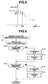
- controller sets control parameter PRM on the basis of friction c estimated at step S32 and with reference to the map shown in Fig. 8. After the execution of step S33, the routine returns to the routine of the landing control.
- control system With the thus arranged control system according to the present invention, it is possible to estimate the actual friction c at the temperature during the resonance initialization, and therefore it becomes possible to reflect the accurate friction c adapted to the change of temperature in the landing control of movable member 6. Therefore, it becomes possible to certainly prevent the collision between movable member 6 and electromagnets 10 and 11 and to increase the operation life of valve 3. Furthermore, since control parameter PRM, particularly, a control gain G is set on the basis of the estimated friction c, the landing control is further executed stably and certainly according to the fluctuation of friction.
Landscapes
- Engineering & Computer Science (AREA)
- Mechanical Engineering (AREA)
- General Engineering & Computer Science (AREA)
- Magnetically Actuated Valves (AREA)
- Valve Device For Special Equipments (AREA)
- Output Control And Ontrol Of Special Type Engine (AREA)
Abstract
Description

Accordingly, if it is possible to estimate friction c according to the condition, this estimation contributes to further accurately estimate velocity v.
Claims (9)
- A valve control system comprising:an electromagnetic valve unit comprisinga valve,a pair of electromagnets arranged in spaced relationship from one another in axial alignment with the valve so as to form a space,a movable member axially movably disposed in the space between the electromagnets, the movable member being interlocked with the valve,a pair of springs biasing the movable member so as to locate the movable member at an intermediate portion of the space when both of the electromagnets are de-energized; anda controller connected to said electromagnetic valve unit, said controller executing an initialization control for moving the movable member to a start position by repeatingly energizing the electromagnets according to a natural frequency of a vibration system of said electromagnetic valve unit, said controller,detecting an amplitude of oscillation of the movable member during the initialization control,calculating an increase-degree of the detected amplitudes, andestimating a friction quantity of the vibration system on the basis of the calculated increase-degree.
- The valve control system as claimed in claim 1, wherein said controller determines a control parameter employed in controlling electric current supplied to the electromagnets, on the basis of the estimated friction quantity.
- The valve control system as claimed in claim 1, wherein said controller detects a temperature corresponding to a temperature of lubricating oil for lubricating movable portions of said electromagnetic valve unit, and stores the estimated friction quantity and the temperature detected during the initialization control corresponding to the estimated friction quantity, as a relationship between the friction quantity and the temperature.
- The valve control system as claimed in claim 3, wherein said controller determines the friction quantity from the relationship and the detected present temperature indicative of lubricating oil temperature, and said controller determines a control parameter employed in controlling electric current supplied to the electromagnets, on the basis of the estimated friction quantity.
- The valve control system as claimed in claim 1, wherein said controller accumulates positions of the movable member during the initialization control and determines a first waveform representative of oscillation of the movable member during the initialization control, said controller determines a second curve representative of the increase-degree of the oscillation during the initialization control from the first waveform.
- The valve control system as claimed in claim 1, wherein said controller comprises a parameter map representing a relationship between a control parameter and the friction quantity and determines the control parameter from the parameter map and the estimated friction quantity.
- An engine valve control system for electromagnetically controlling each of intake and exhaust valves of an internal combustion engine, said valve control system comprising:an electromagnetic valve unit comprisinga pair of electromagnets arranged in spaced relationship from one another in axial alignment with the valve so as to form a space,a movable member axially movably disposed in the space between the electromagnets, the movable member being contacted with the valve,a pair of springs biasing the movable member so as to locate the movable member at an intermediate portion of the space when both of the electromagnets are de-energized; and a controller connected to said electromagnetic valve unit, said controller detecting amplitudes of oscillation of the movable member during the initialization control, said controller calculating an increase-degree of the detected amplitudes, said controller estimating a friction quantity of the vibration system on the basis of the calculated increase-degree, said controller controlling said electromagnetic valve unit on the basis of a control parameter determined by the estimated friction quantity.
- A control system for controlling an electromagnetic valve unit, the electromagnetic valve unit comprising a valve, a pair of electromagnets arranged in spaced relationship from one another in axial alignment with the valve so as to form a space, a movable member axially movably disposed in the space between the electromagnets while being interlocked with the valve, and a pair of springs biasing the movable member so as to locate the movable member at an intermediate portion of the space when both of the electromagnets are de-energized, the control system comprising;initialization amplitude detecting means for detecting amplitudes of oscillation of the movable member during the initialization control;amplitude increase-degree calculating means for calculating an increase-degree of the detected amplitudes;friction quantity estimating means for estimating a friction quantity of the vibration system on the basis of the calculated increase-degree; andcontrolling means for controlling electric current supplied to the electromagnets based on the estimated friction quantity to land the movable member on the electromagnets at a predetermined velocity.
- A method for controlling an electromagnetic valve unit, the electromagnetic valve unit being arranged to operate a valve by electromagnetically controlling a pair of electromagnets so as to displace a movable member disposed in a space between the electromagnets which receiving biasing force of a pair of springs, the method comprising:detecting amplitudes of oscillation of the movable member during the initialization control;calculating an increase-degree of the detected amplitudes;estimating a friction quantity of the vibration system on the basis of the calculated increase-degree; andcontrolling electric current supplied to the electromagnets based on the estimated friction quantity to land the movable member on the electromagnets at a predetermined velocity.
Applications Claiming Priority (2)
| Application Number | Priority Date | Filing Date | Title |
|---|---|---|---|
| JP2000166533A JP3707354B2 (en) | 2000-06-02 | 2000-06-02 | Control device for electromagnetically driven valve |
| JP2000166533 | 2000-06-02 |
Publications (3)
| Publication Number | Publication Date |
|---|---|
| EP1160423A2 true EP1160423A2 (en) | 2001-12-05 |
| EP1160423A3 EP1160423A3 (en) | 2003-05-14 |
| EP1160423B1 EP1160423B1 (en) | 2005-02-23 |
Family
ID=18669833
Family Applications (1)
| Application Number | Title | Priority Date | Filing Date |
|---|---|---|---|
| EP01113316A Expired - Lifetime EP1160423B1 (en) | 2000-06-02 | 2001-05-31 | Control system for controlling an electromagnetic valve unit |
Country Status (4)
| Country | Link |
|---|---|
| US (1) | US6497205B2 (en) |
| EP (1) | EP1160423B1 (en) |
| JP (1) | JP3707354B2 (en) |
| DE (1) | DE60108998T2 (en) |
Cited By (2)
| Publication number | Priority date | Publication date | Assignee | Title |
|---|---|---|---|---|
| CN102979948A (en) * | 2012-11-30 | 2013-03-20 | 中国第一汽车股份有限公司无锡油泵油嘴研究所 | Electromagnetic valve closing-time moment detection circuit of diesel engine electric control system |
| EP2749979A1 (en) * | 2012-12-31 | 2014-07-02 | Bell Helicopter Textron Inc. | Automated diagnostic inspection of mechanical controls |
Families Citing this family (8)
| Publication number | Priority date | Publication date | Assignee | Title |
|---|---|---|---|---|
| US6698408B2 (en) * | 2002-07-10 | 2004-03-02 | Eaton Corporation | Position control strategy EGR valve actuator |
| JP3864874B2 (en) | 2002-08-26 | 2007-01-10 | トヨタ自動車株式会社 | Solenoid valve control device |
| US8079335B2 (en) * | 2009-09-17 | 2011-12-20 | Ford Global Technologies, Llc | Inferred oil responsiveness using pressure sensor pulses |
| DE102012206419B4 (en) | 2012-04-19 | 2021-08-12 | Magna Pt B.V. & Co. Kg | Control for a pressure regulating valve |
| CN103836248A (en) * | 2012-11-22 | 2014-06-04 | 无锡市新兴仪表有限公司 | Electromagnetic valve control device, control system and electromagnetic valve control method |
| US9857801B2 (en) | 2014-03-31 | 2018-01-02 | General Electric Company | System and method for detecting a stick-slip |
| US9920856B2 (en) * | 2014-03-31 | 2018-03-20 | Dresser, Inc. | Method for determining amplitude of stick-slip on a valve assembly and implementation thereof |
| CN104678231A (en) * | 2015-03-25 | 2015-06-03 | 北京理工大学 | Fault detector and initial closing point detector for electromagnetic valve |
Family Cites Families (6)
| Publication number | Priority date | Publication date | Assignee | Title |
|---|---|---|---|---|
| DE3307070C2 (en) * | 1983-03-01 | 1985-11-28 | FEV Forschungsgesellschaft für Energietechnik und Verbrennungsmotoren mbH, 5100 Aachen | Setting device for a switching element that can be adjusted between two end positions |
| DE19733142C2 (en) * | 1997-07-31 | 2001-11-29 | Fev Motorentech Gmbh | Method for initiating the movement of a gas exchange valve actuated by an electromagnetic actuator |
| US6125803A (en) * | 1997-09-22 | 2000-10-03 | Toyota Jidosha Kabushiki Kaisha | Electromagnetically driven valve for an internal combustion engine |
| JP3877851B2 (en) | 1997-11-27 | 2007-02-07 | 株式会社日本自動車部品総合研究所 | Solenoid valve drive |
| EP0992658B1 (en) * | 1998-10-06 | 2003-05-21 | Johnson Controls Automotive Electronics | Electromagnetic valve actuator |
| US6286532B1 (en) * | 2000-05-13 | 2001-09-11 | Ford Global Technologies, Inc. | Control system and method for controlling valve |
-
2000
- 2000-06-02 JP JP2000166533A patent/JP3707354B2/en not_active Expired - Fee Related
-
2001
- 2001-05-21 US US09/860,582 patent/US6497205B2/en not_active Expired - Fee Related
- 2001-05-31 EP EP01113316A patent/EP1160423B1/en not_active Expired - Lifetime
- 2001-05-31 DE DE60108998T patent/DE60108998T2/en not_active Expired - Lifetime
Cited By (2)
| Publication number | Priority date | Publication date | Assignee | Title |
|---|---|---|---|---|
| CN102979948A (en) * | 2012-11-30 | 2013-03-20 | 中国第一汽车股份有限公司无锡油泵油嘴研究所 | Electromagnetic valve closing-time moment detection circuit of diesel engine electric control system |
| EP2749979A1 (en) * | 2012-12-31 | 2014-07-02 | Bell Helicopter Textron Inc. | Automated diagnostic inspection of mechanical controls |
Also Published As
| Publication number | Publication date |
|---|---|
| US6497205B2 (en) | 2002-12-24 |
| JP3707354B2 (en) | 2005-10-19 |
| DE60108998D1 (en) | 2005-03-31 |
| US20010054399A1 (en) | 2001-12-27 |
| EP1160423A3 (en) | 2003-05-14 |
| EP1160423B1 (en) | 2005-02-23 |
| JP2001342855A (en) | 2001-12-14 |
| DE60108998T2 (en) | 2005-07-14 |
Similar Documents
| Publication | Publication Date | Title |
|---|---|---|
| EP1077313B1 (en) | Apparatus for controlling electromagnetically powered engine valve | |
| JP2001515984A (en) | Adjustment operation device operated electromagnetically and method of operating the adjustment operation device | |
| EP1167725B1 (en) | Engine valve drive control apparatus and method | |
| EP2108789B1 (en) | Engine valve drive control apparatus and method | |
| JP2000049012A (en) | Method for controlling the movement of an armature of an electromagnetic actuator | |
| EP1160423B1 (en) | Control system for controlling an electromagnetic valve unit | |
| EP1211389B1 (en) | An electromagnetic valve controller | |
| US6427971B1 (en) | System for controlling electromagnetically actuated valve | |
| JP2001023818A (en) | A method for adjusting the collision speed of a movable piece of an electromagnetic actuator by adjustment based on the characteristic curve of energization | |
| EP1052380B1 (en) | Electromagnetic valve drive and method for controlling same | |
| EP1162349B1 (en) | Apparatus and method for controlling electromagnetically operable engine valve assembly | |
| EP1160422B1 (en) | Control system of electromagnetically operated valve | |
| JP3614092B2 (en) | Valve clearance estimation device and control device for electromagnetically driven valve | |
| US6546903B2 (en) | Control system for electromagnetic actuator | |
| JP2001221360A (en) | Control device for electromagnetically driven valve | |
| JP2002054759A (en) | Control device for electromagnetically driven valve | |
| JP2001221022A (en) | Control device for electromagnetically driven valve | |
| US20090178631A1 (en) | Method of controlling an actuator having a movable member with positional feedback control | |
| JP2002364434A (en) | Engine valve drive controller | |
| JP2001015329A (en) | Valve clearance estimation device for electromagnetically driven valve | |
| JP2001159332A (en) | Control device for electromagnetically driven valve | |
| JP2003343293A (en) | Startup control device for electromagnetically driven valve for internal combustion engine | |
| JP2002081569A (en) | Control device for electromagnetically driven valve |
Legal Events
| Date | Code | Title | Description |
|---|---|---|---|
| PUAI | Public reference made under article 153(3) epc to a published international application that has entered the european phase |
Free format text: ORIGINAL CODE: 0009012 |
|
| 17P | Request for examination filed |
Effective date: 20010531 |
|
| AK | Designated contracting states |
Kind code of ref document: A2 Designated state(s): AT BE CH CY DE DK ES FI FR GB GR IE IT LI LU MC NL PT SE TR |
|
| AX | Request for extension of the european patent |
Free format text: AL;LT;LV;MK;RO;SI |
|
| PUAL | Search report despatched |
Free format text: ORIGINAL CODE: 0009013 |
|
| AK | Designated contracting states |
Designated state(s): AT BE CH CY DE DK ES FI FR GB GR IE IT LI LU MC NL PT SE TR |
|
| AX | Request for extension of the european patent |
Extension state: AL LT LV MK RO SI |
|
| RIC1 | Information provided on ipc code assigned before grant |
Ipc: 7F 02D 41/20 B Ipc: 7F 01L 9/04 A Ipc: 7H 01F 7/16 B Ipc: 7F 02D 41/06 B |
|
| 17Q | First examination report despatched |
Effective date: 20031211 |
|
| AKX | Designation fees paid |
Designated state(s): DE FR GB |
|
| RTI1 | Title (correction) |
Free format text: CONTROL SYSTEM FOR CONTROLLING AN ELECTROMAGNETIC VALVE UNIT |
|
| GRAP | Despatch of communication of intention to grant a patent |
Free format text: ORIGINAL CODE: EPIDOSNIGR1 |
|
| GRAS | Grant fee paid |
Free format text: ORIGINAL CODE: EPIDOSNIGR3 |
|
| GRAA | (expected) grant |
Free format text: ORIGINAL CODE: 0009210 |
|
| AK | Designated contracting states |
Kind code of ref document: B1 Designated state(s): DE FR GB |
|
| REG | Reference to a national code |
Ref country code: GB Ref legal event code: FG4D |
|
| REG | Reference to a national code |
Ref country code: IE Ref legal event code: FG4D |
|
| REF | Corresponds to: |
Ref document number: 60108998 Country of ref document: DE Date of ref document: 20050331 Kind code of ref document: P |
|
| ET | Fr: translation filed | ||
| PLBE | No opposition filed within time limit |
Free format text: ORIGINAL CODE: 0009261 |
|
| STAA | Information on the status of an ep patent application or granted ep patent |
Free format text: STATUS: NO OPPOSITION FILED WITHIN TIME LIMIT |
|
| 26N | No opposition filed |
Effective date: 20051124 |
|
| PGFP | Annual fee paid to national office [announced via postgrant information from national office to epo] |
Ref country code: GB Payment date: 20130529 Year of fee payment: 13 Ref country code: DE Payment date: 20130529 Year of fee payment: 13 |
|
| PGFP | Annual fee paid to national office [announced via postgrant information from national office to epo] |
Ref country code: FR Payment date: 20130531 Year of fee payment: 13 |
|
| REG | Reference to a national code |
Ref country code: DE Ref legal event code: R119 Ref document number: 60108998 Country of ref document: DE |
|
| GBPC | Gb: european patent ceased through non-payment of renewal fee |
Effective date: 20140531 |
|
| REG | Reference to a national code |
Ref country code: DE Ref legal event code: R119 Ref document number: 60108998 Country of ref document: DE Effective date: 20141202 |
|
| REG | Reference to a national code |
Ref country code: FR Ref legal event code: ST Effective date: 20150130 |
|
| PG25 | Lapsed in a contracting state [announced via postgrant information from national office to epo] |
Ref country code: DE Free format text: LAPSE BECAUSE OF NON-PAYMENT OF DUE FEES Effective date: 20141202 |
|
| PG25 | Lapsed in a contracting state [announced via postgrant information from national office to epo] |
Ref country code: FR Free format text: LAPSE BECAUSE OF NON-PAYMENT OF DUE FEES Effective date: 20140602 Ref country code: GB Free format text: LAPSE BECAUSE OF NON-PAYMENT OF DUE FEES Effective date: 20140531 |