EP1160120A2 - Fuel cell system, controller thereof and method of controlling - Google Patents
Fuel cell system, controller thereof and method of controlling Download PDFInfo
- Publication number
- EP1160120A2 EP1160120A2 EP01113063A EP01113063A EP1160120A2 EP 1160120 A2 EP1160120 A2 EP 1160120A2 EP 01113063 A EP01113063 A EP 01113063A EP 01113063 A EP01113063 A EP 01113063A EP 1160120 A2 EP1160120 A2 EP 1160120A2
- Authority
- EP
- European Patent Office
- Prior art keywords
- fuel cell
- battery
- accelerator
- combustor
- charge level
- Prior art date
- Legal status (The legal status is an assumption and is not a legal conclusion. Google has not performed a legal analysis and makes no representation as to the accuracy of the status listed.)
- Granted
Links
Images


Classifications
-
- H—ELECTRICITY
- H01—ELECTRIC ELEMENTS
- H01M—PROCESSES OR MEANS, e.g. BATTERIES, FOR THE DIRECT CONVERSION OF CHEMICAL ENERGY INTO ELECTRICAL ENERGY
- H01M8/00—Fuel cells; Manufacture thereof
- H01M8/04—Auxiliary arrangements, e.g. for control of pressure or for circulation of fluids
- H01M8/04298—Processes for controlling fuel cells or fuel cell systems
- H01M8/04313—Processes for controlling fuel cells or fuel cell systems characterised by the detection or assessment of variables; characterised by the detection or assessment of failure or abnormal function
- H01M8/04537—Electric variables
- H01M8/04604—Power, energy, capacity or load
- H01M8/04619—Power, energy, capacity or load of fuel cell stacks
-
- B—PERFORMING OPERATIONS; TRANSPORTING
- B60—VEHICLES IN GENERAL
- B60L—PROPULSION OF ELECTRICALLY-PROPELLED VEHICLES; SUPPLYING ELECTRIC POWER FOR AUXILIARY EQUIPMENT OF ELECTRICALLY-PROPELLED VEHICLES; ELECTRODYNAMIC BRAKE SYSTEMS FOR VEHICLES IN GENERAL; MAGNETIC SUSPENSION OR LEVITATION FOR VEHICLES; MONITORING OPERATING VARIABLES OF ELECTRICALLY-PROPELLED VEHICLES; ELECTRIC SAFETY DEVICES FOR ELECTRICALLY-PROPELLED VEHICLES
- B60L58/00—Methods or circuit arrangements for monitoring or controlling batteries or fuel cells, specially adapted for electric vehicles
- B60L58/30—Methods or circuit arrangements for monitoring or controlling batteries or fuel cells, specially adapted for electric vehicles for monitoring or controlling fuel cells
-
- H—ELECTRICITY
- H01—ELECTRIC ELEMENTS
- H01M—PROCESSES OR MEANS, e.g. BATTERIES, FOR THE DIRECT CONVERSION OF CHEMICAL ENERGY INTO ELECTRICAL ENERGY
- H01M8/00—Fuel cells; Manufacture thereof
- H01M8/04—Auxiliary arrangements, e.g. for control of pressure or for circulation of fluids
- H01M8/04298—Processes for controlling fuel cells or fuel cell systems
- H01M8/04313—Processes for controlling fuel cells or fuel cell systems characterised by the detection or assessment of variables; characterised by the detection or assessment of failure or abnormal function
- H01M8/0432—Temperature; Ambient temperature
- H01M8/04373—Temperature; Ambient temperature of auxiliary devices, e.g. reformers, compressors, burners
-
- H—ELECTRICITY
- H01—ELECTRIC ELEMENTS
- H01M—PROCESSES OR MEANS, e.g. BATTERIES, FOR THE DIRECT CONVERSION OF CHEMICAL ENERGY INTO ELECTRICAL ENERGY
- H01M8/00—Fuel cells; Manufacture thereof
- H01M8/04—Auxiliary arrangements, e.g. for control of pressure or for circulation of fluids
- H01M8/04298—Processes for controlling fuel cells or fuel cell systems
- H01M8/04313—Processes for controlling fuel cells or fuel cell systems characterised by the detection or assessment of variables; characterised by the detection or assessment of failure or abnormal function
- H01M8/04537—Electric variables
- H01M8/04604—Power, energy, capacity or load
- H01M8/04626—Power, energy, capacity or load of auxiliary devices, e.g. batteries, capacitors
-
- H—ELECTRICITY
- H01—ELECTRIC ELEMENTS
- H01M—PROCESSES OR MEANS, e.g. BATTERIES, FOR THE DIRECT CONVERSION OF CHEMICAL ENERGY INTO ELECTRICAL ENERGY
- H01M8/00—Fuel cells; Manufacture thereof
- H01M8/04—Auxiliary arrangements, e.g. for control of pressure or for circulation of fluids
- H01M8/04298—Processes for controlling fuel cells or fuel cell systems
- H01M8/04694—Processes for controlling fuel cells or fuel cell systems characterised by variables to be controlled
- H01M8/04701—Temperature
- H01M8/04738—Temperature of auxiliary devices, e.g. reformer, compressor, burner
-
- H—ELECTRICITY
- H01—ELECTRIC ELEMENTS
- H01M—PROCESSES OR MEANS, e.g. BATTERIES, FOR THE DIRECT CONVERSION OF CHEMICAL ENERGY INTO ELECTRICAL ENERGY
- H01M8/00—Fuel cells; Manufacture thereof
- H01M8/04—Auxiliary arrangements, e.g. for control of pressure or for circulation of fluids
- H01M8/04298—Processes for controlling fuel cells or fuel cell systems
- H01M8/04694—Processes for controlling fuel cells or fuel cell systems characterised by variables to be controlled
- H01M8/04746—Pressure; Flow
- H01M8/04783—Pressure differences, e.g. between anode and cathode
-
- H—ELECTRICITY
- H01—ELECTRIC ELEMENTS
- H01M—PROCESSES OR MEANS, e.g. BATTERIES, FOR THE DIRECT CONVERSION OF CHEMICAL ENERGY INTO ELECTRICAL ENERGY
- H01M8/00—Fuel cells; Manufacture thereof
- H01M8/04—Auxiliary arrangements, e.g. for control of pressure or for circulation of fluids
- H01M8/04298—Processes for controlling fuel cells or fuel cell systems
- H01M8/04694—Processes for controlling fuel cells or fuel cell systems characterised by variables to be controlled
- H01M8/04858—Electric variables
- H01M8/04925—Power, energy, capacity or load
- H01M8/04947—Power, energy, capacity or load of auxiliary devices, e.g. batteries, capacitors
-
- H—ELECTRICITY
- H01—ELECTRIC ELEMENTS
- H01M—PROCESSES OR MEANS, e.g. BATTERIES, FOR THE DIRECT CONVERSION OF CHEMICAL ENERGY INTO ELECTRICAL ENERGY
- H01M8/00—Fuel cells; Manufacture thereof
- H01M8/06—Combination of fuel cells with means for production of reactants or for treatment of residues
- H01M8/0606—Combination of fuel cells with means for production of reactants or for treatment of residues with means for production of gaseous reactants
- H01M8/0612—Combination of fuel cells with means for production of reactants or for treatment of residues with means for production of gaseous reactants from carbon-containing material
-
- Y—GENERAL TAGGING OF NEW TECHNOLOGICAL DEVELOPMENTS; GENERAL TAGGING OF CROSS-SECTIONAL TECHNOLOGIES SPANNING OVER SEVERAL SECTIONS OF THE IPC; TECHNICAL SUBJECTS COVERED BY FORMER USPC CROSS-REFERENCE ART COLLECTIONS [XRACs] AND DIGESTS
- Y02—TECHNOLOGIES OR APPLICATIONS FOR MITIGATION OR ADAPTATION AGAINST CLIMATE CHANGE
- Y02E—REDUCTION OF GREENHOUSE GAS [GHG] EMISSIONS, RELATED TO ENERGY GENERATION, TRANSMISSION OR DISTRIBUTION
- Y02E60/00—Enabling technologies; Technologies with a potential or indirect contribution to GHG emissions mitigation
- Y02E60/30—Hydrogen technology
- Y02E60/50—Fuel cells
-
- Y—GENERAL TAGGING OF NEW TECHNOLOGICAL DEVELOPMENTS; GENERAL TAGGING OF CROSS-SECTIONAL TECHNOLOGIES SPANNING OVER SEVERAL SECTIONS OF THE IPC; TECHNICAL SUBJECTS COVERED BY FORMER USPC CROSS-REFERENCE ART COLLECTIONS [XRACs] AND DIGESTS
- Y02—TECHNOLOGIES OR APPLICATIONS FOR MITIGATION OR ADAPTATION AGAINST CLIMATE CHANGE
- Y02T—CLIMATE CHANGE MITIGATION TECHNOLOGIES RELATED TO TRANSPORTATION
- Y02T90/00—Enabling technologies or technologies with a potential or indirect contribution to GHG emissions mitigation
- Y02T90/40—Application of hydrogen technology to transportation, e.g. using fuel cells
Definitions
- the present invention relates to a fuel cell system, a controller thereof and a method, and more particularly, to a fuel cell system, a controller thereof and a method for controlling demand power during acceleration in response to a charge level of a battery.
- a start-up control of such a fuel cell system it is a usual practice to monitor a charge level of the battery and to vary the flow rate of feed material to be reformed in the combustor in response to the charge level of the battery.
- a control process is employed wherein when the charge level of the battery is low, a fuel cell is started in operation to charge the battery.
- a fuel cell system is provided with: a fuel cell producing output power; a battery discharging output power; a battery charge level monitoring unit monitoring and detecting a charge level of the battery; an accelerator's displacement sensor detecting an accelerator's displacement value; and a controller calculating demand power to be produced by the fuel cell based on the accelerator's displacement value detected by the accelerator's displacement sensor, calculating an accelerator's displacement value per unit time based on the accelerator's displacement value, and correcting the demand power based on the accelerator's displacement value per unit time and the charge level of the battery detected by the battery charge level monitoring unit.
- a controller of a fuel cell system having a fuel cell producing output power and a battery discharging output power is provided with: means for monitoring and detecting a charge level of the battery; means for detecting an accelerator's displacement value; means for calculating demand power to be produced by the fuel cell based on the accelerator's displacement value; means for calculating an accelerator's displacement value per unit time based on the accelerator's displacement value; and means for correcting the demand power based on the accelerator's displacement value per unit time and the charge level of the battery.
- a method of controlling a fuel cell system which has a fuel cell producing output power and a battery discharging output power, monitoring and detecting a charge level of the battery; detecting an accelerator's displacement value; calculating demand power to be produced by the fuel cell based on the accelerator's displacement value; calculating an accelerator's displacement value per unit time based on the accelerator's displacement value; and correcting the demand power based on the accelerator's displacement value per unit time and the charge level of the battery.
- FIG.1 is a block diagram illustrating a first preferred embodiment of a fuel cell system and a controller thereof according to the present invention.
- the fuel cell system 10 typically applied to a vehicle and includes a control unit 11 which is constructed of a microcomputer and necessary memories (not shown), a combustor 12 which combusts fuel, a hydrogen generator (reformer) 14 which reforms a feed material to produce hydrogen gas H, a fuel cell 16 which generates output power P by achieving electrochemical reaction of hydrogen and air, a compressor 18 which supplies air A to the combustor 12, the hydrogen generator 14 and the fuel cell 16, a fuel supply unit 20 which supplies fuel F to the combustor 12, a material feeding unit 22 which feeds methanol and water as feed material FM to the hydrogen generator 14, a battery 24 which preferably charges output power P generated by the fuel cell 16 and which preferably discharges output power P, a battery charge level monitoring unit 26 which monitors a charge level of the battery 24 to produce a battery charge-level signal BCL, a power distribution controller 28 which controls output power P from the fuel cell 16 and battery 24 to be distributed, a drive train 30 (an external load) which convert
- the hydrogen generator 14 produces hydrogen rich gas by steam reforming methanol and water FM fed from the material feeding unit 22 and air (oxygen) A supplied from the compressor 18, with resultant hydrogen rich gas H being supplied to a fuel electrode (an anode) of the fuel cell 16 while expelling exhaust gas.
- the fuel cell 16 also has an air electrode (cathode), to which air A is supplied from the compressor 18 and also hydrogen containing gas H is supplied from the hydrogen generator 14 as discussed above, with hydrogen and oxygen reacting to generate output power.
- air A is supplied from the compressor 18
- hydrogen containing gas H is supplied from the hydrogen generator 14 as discussed above, with hydrogen and oxygen reacting to generate output power.
- the control unit 11 is constructed having a RAM (not shown) which stores reference data, a ROM (not shown) which stores control programs and a CPU (not shown) which executes various calculation and computation in a manner as will be described below.
- the CPU in the control unit 11 is supplied with the accelerator's displacement signal Acc delivered from the accelerator's displacement sensor 32 and, in response thereto, calculates demand power, thereby producing a demand power signal DP to send to the power distribution controller 28.
- the relationship between the accelerator's displacement signal Acc and demand power is shown in FIG. 5. That is, as viewed in FIG. 5, demand power varies in proportion to the magnitude of the accelerator's displacement signal Acc. Thus, demand power represents the driver's will for acceleration of the vehicle.
- the CPU also in response to the accelerator's displacement signal, calculates an acceleration (accelerator's displacement value per unit time) in response thereto, thereby determining a normal or low-rate acceleration, a medium-rate or slow-rate acceleration and a rapid-rate acceleration, respectively.
- the CPU further functions to correct demand power with a power correction pattern in response to the accelerator's displacement value per unit time and the charge level of the battery in a manner as will be discussed in detail later.
- the hydrogen generator 14 In operation, that is, in a normal operating mode, the hydrogen generator 14 is supplied with feed material FM from the material feeding unit 22 at a feed rate sufficient for allowing the fuel cell 16 to generate an electric power to be required.
- the control unit 11 produces a first command signal 11a which is applied to the material feeding unit 22 such that it feeds raw material FM to the hydrogen generator 14 at a suitable feed rate.
- Feed material FM which is fed to the hydrogen generator 14 from the material feeding unit 22, is reacted to produce hydrogen gas due to chemical reaction.
- Hydrogen gas H thus produced by the hydrogen generator 14 is supplied to the fuel electrode of the fuel cell 16, wherein the hydrogen gas H is subjected to chemical reaction with air A supplied from the compressor 18 to generate electric power output P.
- the control unit 11 also produces a second command signal 11b for controlling the operation of the fuel supply unit 20 and a third command signal 11c for controlling the operation of the compressor 18, both of which are operated in a manner as will be described later.
- Output power P generated in the fuel cell 16 is supplied to the drive train 30 at a rate required for a normal traveling state through the power distributing controller 28.
- hydrogen gas H and air A supplied to the fuel cell 16 are consumed therein at a reaction rate required for electric power generation, and non-reacted hydrogen gas and air are expelled from the fuel cell 16 as surplus hydrogen gas SH and surplus air SA.
- surplus hydrogen gas SH and surplus air SA Surplus hydrogen SH and surplus air SA are then recycled to the combustor 12 wherein these combusts each other, producing thermal energy TE necessary for allowing the hydrogen generator 14 to produce hydrogen gas.
- the fuel cell system 10 operates in a manner described below. That is, as shown in FIG. 2, when the driver depresses an accelerator pedal at the time of start-up or for an acceleration during a halt or during a normal traveling state, the accelerator's displacement sensor 32 detects the driver's will for acceleration to produce an accelerator's displacement signal Acc which is delivered to the control unit 11. As viewed in the graph of FIG. 2, the accelerator's displacement signal Acc is a voltage signal which varies in proportion to the accelerator's displacement value.
- the battery charge level monitoring unit 26 monitors a charge level of the battery 24 at all times and produces a battery charge-level signal BCL, which is applied through the power distribution controller 28 to the control unit 11.
- the power distribution controller 28 monitors the electric power generated in the fuel cell 16, the charge level of the battery 24 and power required by auxiliary units such as the compressor 18 at all times and distributes power output P produced by the fuel cell 16 and power output P discharged by the battery 24 to the drive train 30 at a power level required therefor.
- FIG. 4 shows a control map that is used by the CPU of the control unit 11 to execute correction of demand power in terms of the acceleration, i.e., the accelerator's displacement value per unit time or varying rate of accelerator's displacement value, and the charge level of the battery 24.
- the control map includes a power correction pattern that is determined in terms of the varying rates of the accelerator' s displacement value and the charge level of the battery.
- the control map is composed of first, second and third power correction regions PC1 , PC2 and PC3 for normal acceleration, slow-rate acceleration and rapid-rate acceleration, respectively.
- the first and second power correction regions PC1 and PC2 are defined with a first threshold curve S1
- the second and third power correction regions PC2 and PC3 are defined with a second threshold curve S2, with the first and second threshold curves S1 and S2 tracing threshold values which vary in a linear and oblique manner with a positive inclination.
- demand power is determined merely on a basic incremental value in demand power and a correcting value is not added.
- demand power is determined to have a value wherein a first additional incremental value defined for the slow-rate acceleration is added to a basic incremental value in demand power for such a situation.
- the third power correction region PC3 for the rapid-rate acceleration demand power is determined to have a value wherein a second additional incremental value defined for the rapid-rate acceleration is added to a basic incremental value in demand power for such a situation.
- a power correction value to be added to demand power is determined in terms of the accelerator's displacement value per unit time ⁇ Acc calculated from the above formula and the battery charge level by using the control map shown in FIG. 4.
- the power correction value to be added to demand power varies in response to the charge level of the battery 24 and the varying rate of the accelerator's displacement value, i.e., the rates of acceleration of the vehicle.
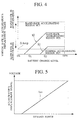
- demand power for the rapid-rate acceleration is equal to a value wherein the second additional incremental value specified for the rapid-rate acceleration is added to the basic incremental value in demand power (see FIG. 8).
- demand power for the slow-rate acceleration is equal to a value wherein the first additional incremental specified for the slow-rate acceleration is added to the basic incremental value in demand power (see FIG. 7).
- demand power varies in dependence on the battery charge level at boundaries corresponding to the linear and oblique lines (that is, corresponding to threshold values S1 and S2) between the normal accelerating state and the slow-rate accelerating state and between the slow-rate and rapid-rate accelerating states.
- power correction value to be added to demand power varies analogously along respective boundary lines between the normal accelerating and slow-rate accelerating states and between the slow-rate accelerating and rapid-rate accelerating states, the vehicle is allowed to achieve smooth acceleration.
- FIG. 6 shows a graph for illustrating demand power in terms of the battery charge level for the normal accelerating state, wherein since the accelerator's displacement value remains at low level, no power correction is implemented to demand power during acceleration.
- FIG. 7 shows a graph for illustrating demand power in terms of the slow-rate accelerating state, wherein the basic incremental value in demand power during the slow-rate acceleration is added with the additional incremental value specified for the slow-rate acceleration.
- FIG. 8 shows a graph for illustrating demand power in terms of the battery charge level for the rapid-rate accelerating state, wherein the basic incremental value in demand is added with the additional incremental value specified for the rapid-rate accelerating state.
- the fuel cell system of the preferred embodiment allows transient demand power to be corrected with the accelerating power correction factor (see FIG. 8) only during acceleration, thereby producing an adequate amount of demand power as to the fuel cell without causing a shortage in output power for thereby meeting an accelerating performance.
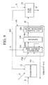
- FIG. 9 shows a block diagram of a second preferred embodiment of a fuel cell system according the present invention, with like parts bearing the same reference numerals as those used in FIG. 1 and detailed description of the like parts being herein omitted for the sake of clarity except the hydrogen generator 14.
- the hydrogen generator 14 is constructed having a feed material evaporator 14a, a reformer 14b and a crude ingredient purifying unit 14c.
- the feed material evaporator 14a includes a heat exchanger which is supplied with feed material FM, containing methanol and water, from the feed material feeding unit 22 and which evaporates feed material in heat exchange with the thermal energy TE fed from the combustor 12, producing evaporated feed material EFM such as evaporated methanol and water.
- the reformer 14b includes a reactor which functions to achieve steam reforming of evaporated methanol, steam and air fed from the compressor 18, producing crude hydrogen rich gas Ho.
- hydrogen rich gas Ho contains carbon monoxide, as toxic ingredient, which deteriorates a catalytic material of the fuel cell 16, carbon monoxide is removed from the crude ingredient purifying unit 14c, producing hydrogen rich gas H with no carbon monoxide.
- demand power is increased during the rapid-rate acceleration in the same manner as in the first preferred embodiment and also fuel F is supplied to the combustor 12 from the fuel supply unit 20 at an increased flow rate to prevent the combustor 12 from being lowered in temperature.
- the combustor 12 is capable of supplying thermal energy, required for generation of hydrogen gas, to the hydrogen generator 14 in a continuous manner, enhancing efficient generation of hydrogen gas with a resultant continuous and stable generation of electric power output.
- the acceleration of the vehicle can be discriminated in terms of the varying rate of the accelerator's displacement value ⁇ Acc with the control map shown FIG.4, and thus the control map shown FIG.4 can be simply used to increase the fuel F.
- the temperature sensor 34 is mounted on the combustor 12 (or in a combustion gas flow passage) to produce a temperature signal T, and the accelerating power correction value to be combined with demand power may be determined by using a control map, shown in FIG. 12, which includes first, second and third correction regions PC4, PC5 and PC6 with threshold curves S3 and S4 that are determined in terms the amount of variation in the temperature of the combustor 12 and the charge level of the battery 24 respectively for normal acceleration, slow-rate acceleration and rapid-rate acceleration.
- a control map shown in FIG. 12, which includes first, second and third correction regions PC4, PC5 and PC6 with threshold curves S3 and S4 that are determined in terms the amount of variation in the temperature of the combustor 12 and the charge level of the battery 24 respectively for normal acceleration, slow-rate acceleration and rapid-rate acceleration.
- a correction value is not added to a flow rate of fuel F to be based
- a correction value for a slow-rate acceleration is added to a flow rate of fuel F to be based
- a correction value for a rapid-rate acceleration is added to a flow rate of fuel F to be based, respectively.
- the decrease in the temperature of the combustor 12 is monitored with the temperature sensor 34 mounted to the combustor 12, thereby making it possible to calculate the amount of increase in the temperature necessary for increasing the flow rate of fuel F supplied to the combustor 12 from the fuel supply unit 20 and, in proportion thereto, for increasing the flow rate of air A to be supplied to the combustor 12 from the compressor 18.
- the fuel cell systems of the first and second preferred embodiments have been described, the fuel cell systems of the present invention may further be modified in a manner described below.
- control of the flow rate of fuel to be supplied to the combustor 12 may be implemented by using a control map which has threshold values such as FIG. 13 different from those used in FIG. 4.
- FIG. 13 is a graph for illustrating this typical example, wherein since the correction factor to be implemented in the flow rate of fuel to prevent temperature drop in the combustor 12 is not unitarily determined in terms of the rate of acceleration, each of threshold curves S5 and S6 is desirably preset to a predetermined value independently of the increase in demand power.
- the control map includes first, second and third correction regions PC7, PC8 and PC9 with the different threshold curves S5 and S6 that are determined in terms of the varying rate of the accelerator's displacement value and the charge level of the battery.
- fuel is supplied from the fuel supply unit 20 to the combustor 12 with a view to increasing demand power during the rapid-rate acceleration and preventing the temperature drop in the combustor 12.
- fuel may be supplied to the combustor 12 at a delayed time relative to the rate of increase in demand power.
- the presence of control in demand power during acceleration in response to a battery charge level allows demand power as to a fuel cell to be settled to an adequately high level necessary for achieving a comfortable accelerating performance even in a slow-rate of acceleration at a low charge level of a battery.
- the temperature of the combustor is increased. Further in this event, the flow rates of fuel and air to the combustor are increased, depending on accelerating correction factors to be added to demand power, allowing the combustor to produce a thermal energy in an efficient manner for enhancing reliable generation of hydrogen to permit the fuel cell to generate electric power in a stable manner.
- determination of the flow rates of fuel and air to the combustor in terms of the operating temperature of the combustor and the charge level of the battery allows the combustor to be supplied with fuel at a suitable flow rate throughout whole operating conditions of the fuel cell system without an abnormal temperature rise caused by supply of fuel at an excessively increased flow rate or an undesirable situation wherein the temperature of the combustor can not be increased.
- supply of fuel to the combustor at a delayed time relative to an increase in demand power allows the supply of fuel to the combustor to be initiated at a time instant suitable for effectively preventing the abnormal temperature rise in the combustor and the situation wherein the temperature of the combustor is not increased.
- the compressor is temporarily interrupted in operation for temporarily interrupting the operation of the fuel cell while allowing the battery to discharge electric power to the electric drive train to achieve a enough accelerating performance.
Landscapes
- Engineering & Computer Science (AREA)
- Sustainable Energy (AREA)
- Life Sciences & Earth Sciences (AREA)
- Sustainable Development (AREA)
- Chemical Kinetics & Catalysis (AREA)
- Chemical & Material Sciences (AREA)
- Manufacturing & Machinery (AREA)
- Electrochemistry (AREA)
- General Chemical & Material Sciences (AREA)
- Power Engineering (AREA)
- Transportation (AREA)
- Mechanical Engineering (AREA)
- Fuel Cell (AREA)
- Electric Propulsion And Braking For Vehicles (AREA)
Abstract
Description
Claims (20)
- A fuel cell system comprising:a fuel cell producing output power;a battery discharging output power;a battery charge level monitoring unit monitoring and detecting a charge level of the battery;an accelerator's displacement sensor detecting an accelerator's displacement value; anda controller calculating demand power to be produced by the fuel cell based on the accelerator's displacement value detected by the accelerator's displacement sensor, calculating an accelerator's displacement value per unit time based on the accelerator's displacement value, and correcting the demand power based on the accelerator's displacement value per unit time and the charge level of the battery detected by the battery charge level monitoring unit.
- A fuel cell system according to claim 1, wherein the controller corrects to increase the demand power.
- A fuel cell system according to claim 1, further comprising:a combustor combusting fuel to produce thermal energy; anda hydrogen generator supplied with the thermal energy and producing hydrogen gas to be supplied to the fuel cell;and wherein surplus hydrogen gas expelled from the fuel cell is recycled to the combustor for combustion therein, and the controller controls temperature of the combustor based on the accelerator's displacement value per unit time and the charge level of the battery.
- A fuel cell system according to claim 3, further comprising a fuel supply unit supplying fuel to the combustor, and wherein the controller controls amount of the fuel supplied to the combustor based on the accelerator's displacement value per unit time and the charge level of the battery.
- A fuel cell system according to claim 4, further comprising a compressor supplying air to the combustor, and wherein the controller controls amount of the air supplied to the combustor based on the accelerator's displacement value per unit time and the charge level of the battery.
- A fuel cell system according to claim 5, wherein the controller controls to supply the fuel and the air to the combustor at a predetermined delayed time after the demand power is corrected.
- A fuel cell system according to claim 5, wherein when the accelerator's displacement value per unit time exceeds a predetermined value and the charge level of the battery exceeds a predetermined value, the controller interrupts the operation of the compressor.
- A fuel cell system according to claim 1, further comprising:a combustor combusting fuel to produce thermal energy;a hydrogen generator supplied with the thermal energy and producing hydrogen gas to be supplied to the fuel cell; anda temperature sensor detecting temperature of the combustor,and wherein surplus hydrogen gas expelled from the fuel cell is recycled to the combustor for combustion therein, and the controller controls temperature of the combustor based on the temperature of the combustor detected by the temperature sensor and the charge level of the battery.
- A fuel cell system according to claim 8, further comprising a fuel supply unit supplying fuel to the combustor, and wherein the controller controls amount of the fuel supplied to the combustor based on the temperature of the combustor and the charge level of the battery.
- A fuel cell system according to claim 9, further comprising a compressor supplying air to the combustor, and wherein the controller controls amount of the air supplied to the combustor based on the temperature of the combustor and the charge level of the battery.
- A fuel cell system according to claim 10, wherein the controller controls to supply the fuel and the air to the combustor at a predetermined delayed time after the demand power is corrected.
- A fuel cell system according to claim 10, wherein when the accelerator's displacement value per unit time exceeds a predetermined value and the charge level of the battery exceeds a predetermined value, the controller interrupts the operation of the compressor.
- A fuel cell system according to claim 1, wherein the controller corrects the demand power by using a control map including a power correction pattern determined in terms of the accelerator's displacement value per unit time and the charge level of the battery.
- A fuel cell system according to claim 13, wherein the power correction pattern has a threshold value linearly changing in response to the charge level of the battery.
- A fuel cell system according to claim 3, wherein the controller controls the temperature of the combustor by using a control map including a power correction pattern determined in terms of the accelerator's displacement value per unit time and the charge level of the battery.
- A fuel cell system according to claim 15, wherein the power correction pattern has a threshold value linearly changing in response to the charge level of the battery.
- A fuel cell system according to claim 3, wherein the controller controls the temperature of the combustor by using a control map including a power correction pattern determined in terms of the temperature of the combustor and the charge level of the battery.
- A fuel cell system according to claim 17, wherein the power correction pattern has a threshold value linearly changing in response to the charge level of the battery.
- A controller of a fuel cell system provided with a fuel cell producing output power and a battery discharging output power, the controller comprising:means for monitoring and detecting a charge level of the battery;means for detecting an accelerator's displacement value;means for calculating demand power to be produced by the fuel cell based on the accelerator's displacement value;means for calculating an accelerator's displacement value per unit time based on the accelerator's displacement value; andmeans for correcting the demand power based on the accelerator' s displacement value per unit time and the charge level of the battery.
- A method of controlling a fuel cell system provided with a fuel cell producing output power and a battery discharging output power, the method comprising:monitoring and detecting a charge level of the battery;detecting an accelerator's displacement value;calculating demand power to be produced by the fuel cell based on the accelerator's displacement value;calculating an accelerator's displacement value per unit time based on the accelerator's displacement value; andcorrecting the demand power based on the accelerator's displacement value per unit time and the charge level of the battery.
Applications Claiming Priority (2)
| Application Number | Priority Date | Filing Date | Title |
|---|---|---|---|
| JP2000159594 | 2000-05-30 | ||
| JP2000159594A JP3721947B2 (en) | 2000-05-30 | 2000-05-30 | Control device for fuel cell system |
Publications (3)
| Publication Number | Publication Date |
|---|---|
| EP1160120A2 true EP1160120A2 (en) | 2001-12-05 |
| EP1160120A3 EP1160120A3 (en) | 2002-04-03 |
| EP1160120B1 EP1160120B1 (en) | 2010-05-12 |
Family
ID=18663895
Family Applications (1)
| Application Number | Title | Priority Date | Filing Date |
|---|---|---|---|
| EP01113063A Expired - Lifetime EP1160120B1 (en) | 2000-05-30 | 2001-05-29 | Fuel cell system, controller thereof and method of controlling |
Country Status (4)
| Country | Link |
|---|---|
| US (1) | US6645653B2 (en) |
| EP (1) | EP1160120B1 (en) |
| JP (1) | JP3721947B2 (en) |
| DE (1) | DE60142098D1 (en) |
Cited By (6)
| Publication number | Priority date | Publication date | Assignee | Title |
|---|---|---|---|---|
| GB2379809A (en) * | 2001-08-31 | 2003-03-19 | Visteon Global Tech Inc | Fuel cell control system |
| WO2004014687A1 (en) * | 2002-07-25 | 2004-02-19 | Daimlerchrysler Ag | Method and arrangement for controlling the energy supply of a mobile device comprising at least one electric driving motor and a hybrid energy system containing a fuel cell system and a dynamic energy system |
| WO2003034527A3 (en) * | 2001-10-16 | 2004-11-04 | Nissan Motor | Control device for fuel cell system and control method |
| FR2854502A1 (en) * | 2003-05-02 | 2004-11-05 | Renault Sa | METHOD AND APPARATUS FOR MANAGING A POWER MODULE COMPRISING A FUEL CELL ON BOARD ON A MOTOR VEHICLE |
| EP1511111A1 (en) * | 2003-08-27 | 2005-03-02 | Nissan Motor Co., Ltd. | Fuel cell system |
| WO2006011368A1 (en) * | 2004-07-30 | 2006-02-02 | Nissan Motor Co., Ltd. | Fuel cell power generating system for executing off gas treatment of fuel cells |
Families Citing this family (33)
| Publication number | Priority date | Publication date | Assignee | Title |
|---|---|---|---|---|
| JP2002141073A (en) | 2000-10-31 | 2002-05-17 | Nissan Motor Co Ltd | Mobile fuel cell system |
| JP3659204B2 (en) * | 2001-08-30 | 2005-06-15 | 日産自動車株式会社 | Mobile fuel cell power plant |
| EP1311048A3 (en) * | 2001-11-09 | 2005-02-16 | Matsushita Electric Industrial Co., Ltd. | Power controller, power generation system and control method of power controller |
| JP3820992B2 (en) * | 2002-01-08 | 2006-09-13 | 日産自動車株式会社 | Fuel cell system |
| JP2003317787A (en) * | 2002-02-21 | 2003-11-07 | Matsushita Electric Ind Co Ltd | Cogeneration vehicle system using fuel cell vehicle and mobile body constituting the system |
| EP1525154A2 (en) * | 2002-07-30 | 2005-04-27 | Hyradix Inc. | Feedforward control processes for variable output hydrogen generators |
| WO2004042843A2 (en) * | 2002-10-30 | 2004-05-21 | Nuvera Fuel Cells, Inc. | Method and system for controlling fluid flow in a fuel processing system |
| FR2847528B1 (en) * | 2002-11-27 | 2005-01-28 | Renault Sa | MOTOR VEHICLE COMPRISING MEANS FOR VARYING THE EXTREME ACTUAL POSITION OF THE ACCELERATION PEDAL |
| US20040126641A1 (en) * | 2002-12-27 | 2004-07-01 | Pearson Martin T. | Regenerative fuel cell electric power plant and operating method |
| US7892304B2 (en) * | 2004-12-17 | 2011-02-22 | Texaco Inc. | Apparatus and method for controlling compressor motor speed in a hydrogen generator |
| JP4783580B2 (en) * | 2005-03-31 | 2011-09-28 | 本田技研工業株式会社 | Fuel cell electrical system, fuel cell vehicle and power supply method |
| JP4555136B2 (en) * | 2005-03-31 | 2010-09-29 | 本田技研工業株式会社 | Fuel cell electrical system, fuel cell vehicle and power supply method |
| JP4353154B2 (en) * | 2005-08-04 | 2009-10-28 | トヨタ自動車株式会社 | Fuel cell vehicle |
| EP1938413A2 (en) * | 2005-08-19 | 2008-07-02 | Millennium Cell Inc. | Hybrid hydrogen fuel systems and methods |
| EP2037522A1 (en) * | 2006-05-09 | 2009-03-18 | Aquafairy Corporation | Charger |
| JP4478707B2 (en) * | 2007-09-06 | 2010-06-09 | 本田技研工業株式会社 | Fuel cell vehicle |
| US8348804B2 (en) * | 2008-01-18 | 2013-01-08 | Caterpillar Inc. | Hybrid engine system with transient load assistance |
| JP4995169B2 (en) * | 2008-09-29 | 2012-08-08 | 三菱重工業株式会社 | Gas turbine control method and apparatus |
| JP4811442B2 (en) * | 2008-09-29 | 2011-11-09 | カシオ計算機株式会社 | Fuel cell system |
| JP5505024B2 (en) * | 2010-03-29 | 2014-05-28 | トヨタ自動車株式会社 | Fuel cell vehicle and control method thereof |
| JP5824165B2 (en) | 2011-12-09 | 2015-11-25 | バラード パワー システムズ インコーポレイテッド | Fuel cell assembly and control method thereof |
| JP5886820B2 (en) * | 2013-12-13 | 2016-03-16 | 株式会社神戸製鋼所 | Gas filling device and gas filling method |
| US9096135B1 (en) * | 2014-09-26 | 2015-08-04 | Proterra Inc. | Acceleration control for an electric vehicle |
| JP6493992B2 (en) * | 2017-01-23 | 2019-04-03 | 株式会社Subaru | Electric vehicle control device and electric vehicle |
| US12111281B2 (en) | 2018-11-21 | 2024-10-08 | Hyaxiom, Inc. | Hydrogen concentration sensor |
| US11824238B2 (en) * | 2019-04-30 | 2023-11-21 | Hyaxiom, Inc. | System for managing hydrogen utilization in a fuel cell power plant |
| DE102019111301B4 (en) * | 2019-05-02 | 2024-11-14 | Schaeffler Technologies AG & Co. KG | DRIVE SYSTEM WITH A FUEL CELL AND A UNIPOLAR MACHINE SUPPLIED THEREWITH AND A MOTOR VEHICLE |
| EP3979375A4 (en) * | 2019-05-27 | 2024-08-07 | Kyocera Corporation | FUEL CELL DEVICE |
| US11768186B2 (en) | 2020-12-08 | 2023-09-26 | Hyaxiom, Inc. | Hydrogen concentration sensor |
| US12000794B2 (en) | 2020-12-08 | 2024-06-04 | Hyaxiom, Inc. | Hydrogen concentration sensor |
| CN112820913B (en) * | 2020-12-31 | 2021-11-12 | 宁波申江科技股份有限公司 | A control system for methanol reforming fuel cell power generation system under variable load conditions |
| CN115303087B (en) * | 2022-06-29 | 2024-09-06 | 山东交通学院 | Speed anti-disturbance control system for hybrid fuel cell vehicle during operating transition phase |
| DE102024113270A1 (en) * | 2024-05-13 | 2025-11-13 | Bayerische Motoren Werke Aktiengesellschaft | Method for operating a vehicle with a fuel cell, vehicle, computer program product and storage medium |
Family Cites Families (23)
| Publication number | Priority date | Publication date | Assignee | Title |
|---|---|---|---|---|
| JPH0451466A (en) | 1990-06-20 | 1992-02-19 | Fuji Electric Co Ltd | Output control device for fuel cell power generation system |
| DE4133014A1 (en) * | 1991-10-04 | 1993-04-08 | Mannesmann Ag | NON-TRACKED VEHICLE WITH ELECTRODYNAMIC CONVERTER AND LEVER |
| JPH05260612A (en) | 1992-03-13 | 1993-10-08 | Hitachi Ltd | Electric car |
| JP2937008B2 (en) * | 1994-04-13 | 1999-08-23 | 三菱自動車工業株式会社 | Hybrid vehicle engine control device |
| JP3429068B2 (en) * | 1994-07-12 | 2003-07-22 | マツダ株式会社 | Hybrid powered electric vehicle |
| JPH097618A (en) | 1995-06-22 | 1997-01-10 | Mitsubishi Electric Corp | Fuel cell power generation system |
| JPH09191506A (en) | 1996-01-11 | 1997-07-22 | Nissan Motor Co Ltd | Electric vehicle controller |
| JPH09306531A (en) * | 1996-05-21 | 1997-11-28 | Toyota Motor Corp | Fuel cell system |
| JP3780568B2 (en) * | 1996-07-05 | 2006-05-31 | トヨタ自動車株式会社 | Control device for hybrid vehicle |
| JP3409661B2 (en) * | 1997-09-29 | 2003-05-26 | 日産自動車株式会社 | Control device for hybrid vehicle |
| DE19747265B4 (en) * | 1997-10-25 | 2010-11-04 | Zf Friedrichshafen Ag | Hybrid drive for a vehicle |
| JPH11164402A (en) * | 1997-11-28 | 1999-06-18 | Aisin Aw Co Ltd | Controller and controlling method for hybrid vehicle |
| JPH11233129A (en) | 1998-02-17 | 1999-08-27 | Mitsubishi Heavy Ind Ltd | Solid electrolyte fuel cell generating system |
| JP3376917B2 (en) * | 1998-06-02 | 2003-02-17 | 三菱自動車工業株式会社 | Hybrid vehicle |
| JP2000036308A (en) * | 1998-07-16 | 2000-02-02 | Toyota Motor Corp | Fuel cell system |
| JP2000034102A (en) * | 1998-07-17 | 2000-02-02 | Toyota Motor Corp | Reformer control device |
| KR20010075224A (en) * | 1998-09-30 | 2001-08-09 | 가나이 쓰도무 | Fuel cell system and vehicle using the system |
| US6638652B1 (en) | 1998-10-02 | 2003-10-28 | Toyota Jidosha Kabushiki Kaisha | Fuel cell control apparatus |
| JP4253920B2 (en) * | 1999-05-06 | 2009-04-15 | 日産自動車株式会社 | Fuel cell vehicle power distribution control device |
| JP4100533B2 (en) * | 1999-05-06 | 2008-06-11 | 日産自動車株式会社 | Temperature controller for exhaust hydrogen combustor in fuel cell vehicle |
| US6428444B1 (en) * | 1999-09-06 | 2002-08-06 | Toyota Jidosha Kabushiki Kaisha | Apparatus for controlling a vehicle and a method of controlling the vehicle |
| JP5140894B2 (en) * | 2000-05-15 | 2013-02-13 | トヨタ自動車株式会社 | Power supply using fuel cell and chargeable / dischargeable power storage unit |
| US6378636B1 (en) * | 2000-10-11 | 2002-04-30 | Ford Global Technologies, Inc. | Method and system for providing for vehicle drivability feel after accelerator release in an electric or hybrid electric vehicle |
-
2000
- 2000-05-30 JP JP2000159594A patent/JP3721947B2/en not_active Expired - Fee Related
-
2001
- 2001-05-24 US US09/863,354 patent/US6645653B2/en not_active Expired - Fee Related
- 2001-05-29 EP EP01113063A patent/EP1160120B1/en not_active Expired - Lifetime
- 2001-05-29 DE DE60142098T patent/DE60142098D1/en not_active Expired - Fee Related
Cited By (10)
| Publication number | Priority date | Publication date | Assignee | Title |
|---|---|---|---|---|
| GB2379809A (en) * | 2001-08-31 | 2003-03-19 | Visteon Global Tech Inc | Fuel cell control system |
| GB2379809B (en) * | 2001-08-31 | 2003-10-29 | Visteon Global Tech Inc | Fuel cell system control |
| US6794844B2 (en) | 2001-08-31 | 2004-09-21 | Visteon Global Technologies, Inc. | Method and system for fuel cell control |
| WO2003034527A3 (en) * | 2001-10-16 | 2004-11-04 | Nissan Motor | Control device for fuel cell system and control method |
| US7052789B2 (en) | 2001-10-16 | 2006-05-30 | Nissan Motor Co., Ltd. | Control device for fuel cell system and control method |
| WO2004014687A1 (en) * | 2002-07-25 | 2004-02-19 | Daimlerchrysler Ag | Method and arrangement for controlling the energy supply of a mobile device comprising at least one electric driving motor and a hybrid energy system containing a fuel cell system and a dynamic energy system |
| US7487851B2 (en) | 2002-07-25 | 2009-02-10 | Daimler Ag | Method and apparatus for controlling a hybrid power supply system in a vehicle |
| FR2854502A1 (en) * | 2003-05-02 | 2004-11-05 | Renault Sa | METHOD AND APPARATUS FOR MANAGING A POWER MODULE COMPRISING A FUEL CELL ON BOARD ON A MOTOR VEHICLE |
| EP1511111A1 (en) * | 2003-08-27 | 2005-03-02 | Nissan Motor Co., Ltd. | Fuel cell system |
| WO2006011368A1 (en) * | 2004-07-30 | 2006-02-02 | Nissan Motor Co., Ltd. | Fuel cell power generating system for executing off gas treatment of fuel cells |
Also Published As
| Publication number | Publication date |
|---|---|
| EP1160120A3 (en) | 2002-04-03 |
| EP1160120B1 (en) | 2010-05-12 |
| JP2001339810A (en) | 2001-12-07 |
| US20010051290A1 (en) | 2001-12-13 |
| JP3721947B2 (en) | 2005-11-30 |
| DE60142098D1 (en) | 2010-06-24 |
| US6645653B2 (en) | 2003-11-11 |
Similar Documents
| Publication | Publication Date | Title |
|---|---|---|
| EP1160120B1 (en) | Fuel cell system, controller thereof and method of controlling | |
| EP1485961B1 (en) | Fuel cell system and its control method | |
| US6638653B2 (en) | Fuel cell system | |
| US7059436B2 (en) | Operating load control for fuel cell power system in fuel cell vehicle | |
| US6497972B1 (en) | Fuel cell system and method for controlling operating pressure thereof | |
| JP3979057B2 (en) | Control device for fuel cell system | |
| US20030124400A1 (en) | Fuel cell power generation system and control method thereof | |
| US6627342B1 (en) | Evaporator liquid fuel injection apparatus and fuel cell system | |
| CN102484271A (en) | Control Device And Control Method For Fuel Cell System | |
| EP0993060B1 (en) | Fuel cell control apparatus and method of controlling fuel cell using control apparatus | |
| JPH1131521A (en) | Fuel cell system and power load prediction device | |
| EP1556937B1 (en) | Electric power generation control system and electric power generation control method for fuel cell | |
| JP2005253270A (en) | Control device for fuel cell vehicle | |
| US8148033B2 (en) | Fuel cell system with suppressed noise and vibration | |
| US6887603B2 (en) | Raw fuel vaporizing apparatus, method of vaporizing raw fuel, and fuel cell system equipped with raw fuel vaporizing apparatus | |
| JP6826436B2 (en) | Fuel cell system and its operation method | |
| JP2006040718A (en) | Fuel cell system | |
| US20060191202A1 (en) | Fuel reforming system | |
| US6607855B2 (en) | Control system for fuel cell | |
| JP4287563B2 (en) | Method for treating surplus reformed fuel gas in fuel reforming type fuel cell power supply system | |
| JP2002117875A (en) | Control device for fuel cell system | |
| JP4596657B2 (en) | Fuel cell system | |
| JP2006109650A (en) | Vehicle control apparatus and vehicle control method | |
| JP3664044B2 (en) | Vehicle fuel cell system | |
| JP3876763B2 (en) | Control device for fuel cell system |
Legal Events
| Date | Code | Title | Description |
|---|---|---|---|
| PUAI | Public reference made under article 153(3) epc to a published international application that has entered the european phase |
Free format text: ORIGINAL CODE: 0009012 |
|
| 17P | Request for examination filed |
Effective date: 20010529 |
|
| AK | Designated contracting states |
Kind code of ref document: A2 Designated state(s): DE FR GB Kind code of ref document: A2 Designated state(s): AT BE CH CY DE DK ES FI FR GB GR IE IT LI LU MC NL PT SE TR |
|
| AX | Request for extension of the european patent |
Free format text: AL;LT;LV;MK;RO;SI |
|
| PUAL | Search report despatched |
Free format text: ORIGINAL CODE: 0009013 |
|
| AK | Designated contracting states |
Kind code of ref document: A3 Designated state(s): AT BE CH CY DE DK ES FI FR GB GR IE IT LI LU MC NL PT SE TR |
|
| AX | Request for extension of the european patent |
Free format text: AL;LT;LV;MK;RO;SI |
|
| AKX | Designation fees paid |
Free format text: DE FR GB |
|
| GRAP | Despatch of communication of intention to grant a patent |
Free format text: ORIGINAL CODE: EPIDOSNIGR1 |
|
| GRAS | Grant fee paid |
Free format text: ORIGINAL CODE: EPIDOSNIGR3 |
|
| GRAA | (expected) grant |
Free format text: ORIGINAL CODE: 0009210 |
|
| AK | Designated contracting states |
Kind code of ref document: B1 Designated state(s): DE FR GB |
|
| REG | Reference to a national code |
Ref country code: GB Ref legal event code: FG4D |
|
| REF | Corresponds to: |
Ref document number: 60142098 Country of ref document: DE Date of ref document: 20100624 Kind code of ref document: P |
|
| PLBE | No opposition filed within time limit |
Free format text: ORIGINAL CODE: 0009261 |
|
| STAA | Information on the status of an ep patent application or granted ep patent |
Free format text: STATUS: NO OPPOSITION FILED WITHIN TIME LIMIT |
|
| 26N | No opposition filed |
Effective date: 20110215 |
|
| GBPC | Gb: european patent ceased through non-payment of renewal fee |
Effective date: 20100812 |
|
| PG25 | Lapsed in a contracting state [announced via postgrant information from national office to epo] |
Ref country code: DE Free format text: LAPSE BECAUSE OF NON-PAYMENT OF DUE FEES Effective date: 20101201 |
|
| PG25 | Lapsed in a contracting state [announced via postgrant information from national office to epo] |
Ref country code: GB Free format text: LAPSE BECAUSE OF NON-PAYMENT OF DUE FEES Effective date: 20100812 |
|
| PG25 | Lapsed in a contracting state [announced via postgrant information from national office to epo] |
Ref country code: FR Free format text: LAPSE BECAUSE OF NON-PAYMENT OF DUE FEES Effective date: 20100712 |