EP1160063A1 - Motor-operated stapler - Google Patents
Motor-operated stapler Download PDFInfo
- Publication number
- EP1160063A1 EP1160063A1 EP01250195A EP01250195A EP1160063A1 EP 1160063 A1 EP1160063 A1 EP 1160063A1 EP 01250195 A EP01250195 A EP 01250195A EP 01250195 A EP01250195 A EP 01250195A EP 1160063 A1 EP1160063 A1 EP 1160063A1
- Authority
- EP
- European Patent Office
- Prior art keywords
- bundle
- sheets
- clincher
- clinchers
- magazine
- Prior art date
- Legal status (The legal status is an assumption and is not a legal conclusion. Google has not performed a legal analysis and makes no representation as to the accuracy of the status listed.)
- Granted
Links
- 230000033001 locomotion Effects 0.000 claims abstract description 43
- 230000007246 mechanism Effects 0.000 claims description 24
- 238000013459 approach Methods 0.000 claims description 5
- 238000005452 bending Methods 0.000 description 6
- 238000010586 diagram Methods 0.000 description 3
- 125000006850 spacer group Chemical group 0.000 description 2
- 239000000853 adhesive Substances 0.000 description 1
- 230000001070 adhesive effect Effects 0.000 description 1
- 238000003780 insertion Methods 0.000 description 1
- 230000037431 insertion Effects 0.000 description 1
- 239000004973 liquid crystal related substance Substances 0.000 description 1
- 230000003287 optical effect Effects 0.000 description 1
- 230000002093 peripheral effect Effects 0.000 description 1
Images




Classifications
-
- B—PERFORMING OPERATIONS; TRANSPORTING
- B27—WORKING OR PRESERVING WOOD OR SIMILAR MATERIAL; NAILING OR STAPLING MACHINES IN GENERAL
- B27F—DOVETAILED WORK; TENONS; SLOTTING MACHINES FOR WOOD OR SIMILAR MATERIAL; NAILING OR STAPLING MACHINES
- B27F7/00—Nailing or stapling; Nailed or stapled work
- B27F7/17—Stapling machines
- B27F7/19—Stapling machines with provision for bending the ends of the staples on to the work
- B27F7/21—Stapling machines with provision for bending the ends of the staples on to the work with means for forming the staples in the machine
Definitions
- the present invention relates to a motor-operated stapler for bending leg portions of a staple in a well-shaped state along a bundle of sheets to be stapled irrespective of the thickness of the bundle of sheets.
- a stack tray of a copying machine which tray is provided with a motor-operated stapler.
- a motor-operated stapler a large number of rectilinear wires are arranged in parallel to form sheet-like staples, then a large number of such sheet-like staples are stacked within a cartridge and are sent out one by one from a delivery port formed in the cartridge.
- the cartridge can be accommodated with a magazine which is provided with staple forming/drive-ont means.
- a clincher base having a flat paper carrying surface for carrying a copying paper bundle thereon.
- the clincher base is slidably vertically with respect to the magazine so that the copying paper carrying surface thereof can approach or leave the magazine, thereby permitting a copying paper bundle to be pinched between the magazine and the copying paper carrying surface.
- a slot is formed in the copying paper carrying surface for insertion therein of leg portions of a U-shaped staple, and a pair of clinchers are disposed pivotably within the slat to bend leg portions of the staple inwards along the copying paper bundle.
- the clincher base is provided with a pair of clincher links for moving the paired clinchers pivotally, the clinchers being engaged respectively with one ends of the paired clincher links.
- a pair of cams for moving the paired clincher links pivotally, with opposite ends of the clincher links being engaged with the cams respectively.
- the cam for moving the clincher links pivotally is rotated by means of a motor which serves as a drive source for driving the magazine and a gear mechanism.
- the opposite end portions of the paired clincher links move pivotally following the rotation of the paired cams, while one end portions of the clincher links respectively cause the clinchers to turn, thereby bending the leg portions of the staple along the copying paper bundle.
- the clincher base is held vertically movably by the housing which holds the magazine and the clincher links, which are secured with shafts to the clincher base, move pivotally after a bundle of sheets to be stapled has been held between the magazine and the clincher base, so that the amount of the pivotal movement of clincher links differ depending on the thickness of the bundle of sheets to be stapled.
- the present invention has been accomplished in view of the above-mentioned problems and it is an object of the invention to provide a motor-operated stapler of the type wherein a clincher base is held vertically movably on a magazine side and clincher links are pivotally moved by means of a drive source provided on the magazine side and leg portions of a staple are bent by clinchers, characterized in that the staple leg portions projecting from the underside of a bundle of sheets to be stapled can be bent at a predetermined certain angle irrespective of the thickness of the bundle of sheets to be stapled.
- a motor-operated stapler wherein a bundle of sheets to be stapled is held by both a magazine which houses therein a staple forming mechanism and a plurality of staples and a clincher base which is movable in the thickness direction of the bundle of sheets and which is driven by a drive source provided on the magazine side, a staple is driven out from the magazine into the bundle of sheets, and leg portions of the staple projecting downward from the bundle of sheets are bent along the bundle of sheets by a pair of clinchers mounted on the clincher base, characterized by including clinchers' pivotal movement control means which keep the amount of pivotal movement of the clinchers constant irrespective of the thickness of the bundle of sheets.
- a motor-operated stapler further including a clincher pivoting mechanism for moving the clinchers pivotally, the clincher pivoting mechanism comprising clincher links installed on the clincher base to move the clinchers vertically pivotally, driven cam surfaces formed respectively on the clincher links and extending in the thickness direction of the bundle of sheets to be stapled, fulcrums which convert swing motions of the cam surfaces into pivotal motions of the clinchers, and driving cams installed on fixing means side which hold the magazine, the driving cams coming into contact with the driven cam surfaces of the clincher links and being rotated by the drive source provided on the magazine side, and wherein the clinchers' pivotal movement control means are formed respectively in upper areas of the driven cam surfaces with which the driving cams are in contact and are constituted respectively by projections for causing the clinchers to further turn in a direction to approach the surface of the bundle of sheets.
- a motor-operated stapler further including a clincher pivoting mechanism for moving the clinchers pivotally, the clincher pivoting mechanism comprising clincher links installed on the clincher base to move the clinchers vertically pivotally, driven cam surfaces formed respectively on the clincher links and extending in the thickness direction of the bundles of sheets to be stapled, fulcrums which convert swing motions of the cam surfaces into pivotal motions of the clinchers, and driving cams installed on fixing means side which hold the magazine, the driving cams coming into contact with the driven cam surfaces of the clincher links and being rotated by the drive source provided on the magazine side, and wherein the clinchers' pivotal movement control means are constructed so that when the thickness of the bundle of sheets exceeds a predetermined value with respect to the length of staple leg portions, the distance between an abutment position and each of the fulcrums which abutment position is the position of abut
- Fig. 1 illustrates the configuration of a principal mechanism for driving clinchers in the motor-operated stapler which is indicated at 1.
- the reference numeral 2 denotes a magazine
- the numeral 3 denotes a clincher base
- numeral 4 denotes a clincher
- numeral 5 denotes a clincher link
- numeral 6 denotes a driving cam
- numeral 7 denotes a bundle of sheets to be stapled.
- the motor-operated stapler 1 is also provided with other mechanisms than the mechanism shown in Fig. 1, such as a control unit and a driver motor, but a principal mechanism for driving clinchers is shown in Fig. 1.
- the magazine 2 has a cartridge 10 which receives therein a large number of joined staple members 9 in a stacked state, the joined staple members 9 each comprising straight wire-like staples 11 which are joined together in the shape of sheet, and a well known feeding means which send out the joined staple members 9 for each staple thickness, i.e., staple by staple, from the cartridge 10 and a driver 12 which drives out each staple 6 thus sent out into the bundle of sheets 7 after the staple has been bent in U shape by a forming plate 14.
- Each joined staple member 9 comprises, say, one hundred wire-like staples 11 arranged in parallel and joined together with an adhesive so as to be separable one by one using the driver 12.
- the interior of the cartridge 10 is formed so as to permit a large number of the joined staple members 9 to be accommodated therein in a stacked state and also permit the joined staple members 9 to be sent out staple by staple leftwards in Fig. 1(B) from a lower portion of the cartridge 10.
- the driver 12 is for causing each U-shaped staple 11 to pierce into the bundle of sheets 7.
- an anvil 13 which supports the staple 11 and the forming plate 14 which bends both sides of the staple into U shape while the staple is carried on the anvil 13.
- the driver 12 and the forming plate 14 are integrally superimposed one on the other in a front and rear relation to each other and are adapted to move together vertically.
- the forming plate 14 has a recess 14A for forming both sides of the wire-like staple 11 into U shape, the staple 11 being supported by the anvil 13.
- the driver 12, as shown in Fig. 7, has a convex portion 12A for driving out the staple 11 thus formed in U shape into the bundle of sheets 7.
- the forming plate 14 When the driver 12 has driven out a U shaped staple 11 completely into the bundle of sheets 7, the forming plate 14 has completed its work of forming the leg portions 11'A of the next staple 11' into U shape.
- the clincher base 3 is held vertically movably by a chassis (not shown) of the motor-operated stapler which chassis holds the magazine 2, and it is driven by a drive mechanism and a control unit both mounted to the chassis.
- the drive mechanism is made up of a motor M and a gear mechanism G
- the control unit is composed of a microcomputer and a peripheral circuit connected to the microcomputer.
- a sensor for detecting that the bundle of sheets 7 has been fed is constituted by a microswitch or an optical sensor.
- the drive mechanism is operated through the control unit, whereby the clincher base 3 is moved upward and holds the bundle of sheets 7 between it and the magazine 2.
- the thickness of the bundle of sheets 7 inserted between the table 3A of the clincher base 3 and the magazine 2 is set beforehand to a thickness which permits the bundle to be stapled by each staple 11.
- a microswitch for example is disposed within the area of movement of the clincher base 3.
- a microswitch which determines an upper limit value in thickness of the bundle of sheets 7 when the clincher base 3 holds the bundle of sheets 7 between it and the magazine 2.
- the microswitch detects that the thickness of the bundle of sheets 7 has exceeded the upper limit value, it sends the detected signal to the control unit.
- the thickness of the bundle of sheets 7 is a thickness at which the bundle cannot be stapled by the staple 11
- this state is detected, for example, by a sensor which detects the amount of movement of the clincher base 3 and the detected aignal is outputted to the control unit.
- the control unit inhibits the driver 12 from driving out the staple 11, causes the clincher base-3 to move down, thereby releasing the bundle of sheets 7, and further causes display means, e.g., a liquid crystal display, to make a display that stapling is not performed.
- both ends of a front end portion 15 of the clincher base 3 toward which the bundle of sheets 7 is inserted are integral with L-shaped side plate portions 16 respectively.
- the front end portion 15 of the clincher base 3 is formed substantially in the shape of a flat plate, and spacers 17 which support the clinchers 4 are attached to the back of the front end portion 15 of the clincher base 3.
- a table 3A whose front end is bent downward is fixed with screws to the clincher base 3 at a position where the bundle of sheets 7 is rested.
- the table 3A which is for carrying the bundle of sheets 7 thereon, there is formed an opening 3B permitting vertical movements of the paired clinchers 4.
- the opening 3B permits the clinchers 4 pass therethrough for bending the leg portions of each staple 11 in parallel with the back sheet of the bundle 7.
- the pair of clinchers 4 are pivotably held respectively with pins 17A of the spacers 17 and are pulled downward from chord springs (not shown). Upper surfaces of the clinchers 4 face the positions of dot-dash lines B in Fig. 1.
- the clincher links 5 are respectively supported by pins 18 (fulcrums) provided respectively on the right and left side plate portions 16 of the clincher base 3.
- the clincher links 5 each have a generally L-shaped side shape.
- a cam plate portion 19 which is bent at nearly right angles from the clincher link.
- the cam plate portion of each clincher link 5 is inserted into a recess 4A of the associated clincher 4, whereby a pivotal motion of the clincher link 5 is transmitted to the clincher 4.
- each clincher link 5 is formed with an abutting portion 20 (a driven cam surface) for abutment therewith of the driving cam 6 with a vertical movement of the clincher base 3.
- abutting portions 20 of the paired clincher links 5 rotation of the driving cams 6 causes a pivotal motion of the clinchers 4 no matter how thick the bundle of sheets 7 may be.
- An upper part of the abutting portion 20 is an area with which the driving cam 6 comes into contact when the bundle of sheets 7 is thick, and an auxiliary projection 21 is formed on the upper part of the abutting portion 20.
- the abutting portion 20 and the auxiliary projection 21 constitute clincher's pivotal movement control means.
- the auxiliary projection 21 is for obtaining the same amount of pivotal movement of each clincher 4 as that in case of the bundle of sheet 7 being thin even when the bundle is thick, and causes the leg portions of each staple 11 to be bent along the bundle of sheets 7 in the same manner as in case of the bundle being thin even when the staple leg portions are short.
- Each driving cam 6 is held with a pin 23 fixed to the chassis (fixing member, not shown) of the motor-operated stapler 1 which chassis holds and fixes the magazine 2, and is rotated by a cam 22.
- a cylindrical shaft 24 is mounted to the driving cam 6 at a position at which the driving cam comes into contact with the abutting portion 20.
- the driving cam 6 is rotated, the shaft 24 pushes the abutting portion 20, causing the associated clincher link 5 to turn.
- the cam 22 which causes the driving cam 6 to rotate is fixed with a pin 25.
- the pin 25 is driven through a drive motor and a reduction mechanism (neither shown) installed in the motor-operated stapler 1.
- the position of the clincher base 8 varies vertically according to the thickness of the sheets bundle, but since the abutting portions 20 of the clincher links 5 are formed correspondingly to the thickness of the sheets bundle 7, the driving cams 6 come into contact with the clincher links 5 at a nearly constant angle, so even upon rotation thereof the amount of pivotal movement of the clincher links 5 does not change according to the thickness of the sheets bundle 7, so that the clinchers 4 which pivot in accordance with the pivotal movement of the clincher links 5 are always constant in the amount of their pivotal motion.
- the leg portions 11A of each staple 11 can be bent always in a constant state.
- the magazine 2 and the clincher base 3 can hold the bundle therebetween.
- the clincher links 5 revert to their original stand-by positions and the clinchers 4 turn below the table 3A, as is seen from the cam surface shape of the driving cams 6. Further, the clincher base 3 is retracted from the magazine 2 and the sheets bundle 7 thus stapled is released. The sheets bundle 7 thus released is then sent to a stack tray by feed rollers of a copying machine on which the motor-operated stapler 1 is mounted.
- each abutting portion 20 in the clincher base 3 is formed the auxiliary projection 21 as clincher's pivotal movement control means to keep the pivotal movement of the associated clincher link 5 constant no matter at which position the driving cam 6 may be abutted against the abutting portion 20.
- the clincher's pivotal movement control means is constituted by the abutting portion 20 and the auxiliary projection 21, no limitation is made thereto.
- a curved surface 20A (see Fig. 4(B)) which projects gently toward the driving cam 6, or an inclined surface 20B (see Fig. 4(C)), may be formed as a guide surface above the abutting portion 20, and both this guide surface and the abutting portion 20 may constitute the clincher's pivotal movement control means.
- a driven cam provided with the auxiliary projection 21 may be provided separately on each clincher link 5 side so as to be vertically adjustable by an adjusting lever with use of a link mechanism or the like.
- the bundle of sheets is pinched and held between the magazine and the clincher base.
- the driving cams provided on the magazine side are rotated, whereby the clincher links move pivotally and bend leg portions of a staple projecting from the bundle of sheets.
- the motor-operated stapler in the third aspect of the present invention by constituting a link mechanism in such a manner that even when the thickness of a bundle of sheets is larger than a predetermined value with respect to the length of leg portions of a staple, there is ensured the same amount of pivotal movement of each clincher as in the case of a thin sheets bundle, staple leg portions projecting from the bundle of sheets can be bent along the back of the bundle even if the bundle is thick.
- a motor-operated stapler of the type wherein a clincher base which pinches and holds a bundle of sheets in cooperation with a magazine is held on the magazine side and clincher links are pivotally moved by means of a drive source provided on the magazine side, even when the distance between an abutting point of each clincher link against a driving cam and a pivotal fulcrum varies depending on the thickness of a sheets bundle, staple leg portions projecting from the underside of the sheets bundle can be bent at a predetermined certain angle.
- staple leg portions are prevented from being bent to excess and again piercing through the bundle of sheets, while in the case of a thick bundle of sheets, staple leg portions can be bent to a sufficient degree, whereby the bundle of sheets can be prevented from coming off the staple leg portions.
Landscapes
- Engineering & Computer Science (AREA)
- Mechanical Engineering (AREA)
- Life Sciences & Earth Sciences (AREA)
- Forests & Forestry (AREA)
- Portable Nailing Machines And Staplers (AREA)
- Dovetailed Work, And Nailing Machines And Stapling Machines For Wood (AREA)
Abstract
Description
- The present invention relates to a motor-operated stapler for bending leg portions of a staple in a well-shaped state along a bundle of sheets to be stapled irrespective of the thickness of the bundle of sheets.
- Heretofore there has been known a stack tray of a copying machine which tray is provided with a motor-operated stapler. In this motor-operated stapler, a large number of rectilinear wires are arranged in parallel to form sheet-like staples, then a large number of such sheet-like staples are stacked within a cartridge and are sent out one by one from a delivery port formed in the cartridge. The cartridge can be accommodated with a magazine which is provided with staple forming/drive-ont means.
- Below the magazine is disposed a clincher base having a flat paper carrying surface for carrying a copying paper bundle thereon. The clincher base is slidably vertically with respect to the magazine so that the copying paper carrying surface thereof can approach or leave the magazine, thereby permitting a copying paper bundle to be pinched between the magazine and the copying paper carrying surface.
- A slot is formed in the copying paper carrying surface for insertion therein of leg portions of a U-shaped staple, and a pair of clinchers are disposed pivotably within the slat to bend leg portions of the staple inwards along the copying paper bundle.
- The clincher base is provided with a pair of clincher links for moving the paired clinchers pivotally, the clinchers being engaged respectively with one ends of the paired clincher links.
- On a magazine housing side, to which the magazine is fixed, there are provided a pair of cams for moving the paired clincher links pivotally, with opposite ends of the clincher links being engaged with the cams respectively.
- The cam for moving the clincher links pivotally is rotated by means of a motor which serves as a drive source for driving the magazine and a gear mechanism.
- If the paired cams are rotated when the copying paper bundle is pinched between the magazine and a clincher table of the clincher base, the opposite end portions of the paired clincher links move pivotally following the rotation of the paired cams, while one end portions of the clincher links respectively cause the clinchers to turn, thereby bending the leg portions of the staple along the copying paper bundle.
- In such a conventional motor-operated stapler, however, the clincher base is held vertically movably by the housing which holds the magazine and the clincher links, which are secured with shafts to the clincher base, move pivotally after a bundle of sheets to be stapled has been held between the magazine and the clincher base, so that the amount of the pivotal movement of clincher links differ depending on the thickness of the bundle of sheets to be stapled.
- Therefore, if a copying paper bundle to be stapled is thick, the length of the staple leg portions projecting from the copying paper bundle is short and the distance from an abutment point between a fulcrum of each clincher link and each cam as a drive source becomes long, so that the amount of the pivotal movement of clincher links becomes small. Consequently, the amount of the pivotal movement for bending the staple leg portions projecting from the bundle of sheets to be stapled becomes small and there easily occurs a case where the leg portions cannot be bent sufficiently, with consequent occurrence of inconveniences such as the copying paper bundle being caught on projections or the like formed on a desk.
- On the other hand, in the case of a thin copying paper bundle, the staple leg portions projecting from the underside of the bundle of sheets to be stapled is long and the distance from the abutment point of the clincher link fulcrum with the driving cam becomes short, so that the amount of the pivotal movement of clincher links becomes large. Consequently, the angle of the clinchers' pivotal movement becomes large and there may occur a case where the bent leg portions of the staple again pierces through the copying paper bundle.
- The present invention has been accomplished in view of the above-mentioned problems and it is an object of the invention to provide a motor-operated stapler of the type wherein a clincher base is held vertically movably on a magazine side and clincher links are pivotally moved by means of a drive source provided on the magazine side and leg portions of a staple are bent by clinchers, characterized in that the staple leg portions projecting from the underside of a bundle of sheets to be stapled can be bent at a predetermined certain angle irrespective of the thickness of the bundle of sheets to be stapled.
- For achieving the above-mentioned object, according to the present invention there is provided, in the first aspect thereof, a motor-operated stapler wherein a bundle of sheets to be stapled is held by both a magazine which houses therein a staple forming mechanism and a plurality of staples and a clincher base which is movable in the thickness direction of the bundle of sheets and which is driven by a drive source provided on the magazine side, a staple is driven out from the magazine into the bundle of sheets, and leg portions of the staple projecting downward from the bundle of sheets are bent along the bundle of sheets by a pair of clinchers mounted on the clincher base, characterized by including clinchers' pivotal movement control means which keep the amount of pivotal movement of the clinchers constant irrespective of the thickness of the bundle of sheets.
- In the second aspect of the present invention there is provided, in combination with the above first aspect, a motor-operated stapler further including a clincher pivoting mechanism for moving the clinchers pivotally, the clincher pivoting mechanism comprising clincher links installed on the clincher base to move the clinchers vertically pivotally, driven cam surfaces formed respectively on the clincher links and extending in the thickness direction of the bundle of sheets to be stapled, fulcrums which convert swing motions of the cam surfaces into pivotal motions of the clinchers, and driving cams installed on fixing means side which hold the magazine, the driving cams coming into contact with the driven cam surfaces of the clincher links and being rotated by the drive source provided on the magazine side, and wherein the clinchers' pivotal movement control means are formed respectively in upper areas of the driven cam surfaces with which the driving cams are in contact and are constituted respectively by projections for causing the clinchers to further turn in a direction to approach the surface of the bundle of sheets.
- In the third aspect of the present invention there is provided, in combination with the above first aspect, a motor-operated stapler further including a clincher pivoting mechanism for moving the clinchers pivotally, the clincher pivoting mechanism comprising clincher links installed on the clincher base to move the clinchers vertically pivotally, driven cam surfaces formed respectively on the clincher links and extending in the thickness direction of the bundles of sheets to be stapled, fulcrums which convert swing motions of the cam surfaces into pivotal motions of the clinchers, and driving cams installed on fixing means side which hold the magazine, the driving cams coming into contact with the driven cam surfaces of the clincher links and being rotated by the drive source provided on the magazine side, and wherein the clinchers' pivotal movement control means are constructed so that when the thickness of the bundle of sheets exceeds a predetermined value with respect to the length of staple leg portions, the distance between an abutment position and each of the fulcrums which abutment position is the position of abutment between each of the clincher links and each of the clinchers is increased relatively with respect to the distance between an abutment position and each of the fulcrums which abutment position is the position of abutment between each of the clincher links and each of the driving cams.
-
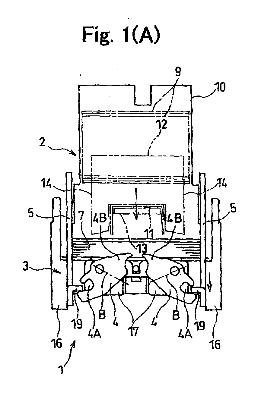
- Fig. 1(A) is an enlarged front view showing a magazine and a mechanism for driving clinchers abutted against clincher links in a motor-operated stapler according to an embodiment of the present invention, and Fig. 1(B) is an enlarged view of a side portion;
- Fig. 2(A) illustrates a back configuration of a clincher base and Fig. 2(B) illustrates a side configuration of the clincher base;
- Fig. 3 illustrates a mounted state of only one of the clinchers which are mounted to the clincher base;
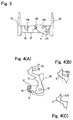
- Fig. 4(A) illustrates a side shape of a clincher link, Fig. 4(B) is a partial diagram wherein a curved surface projecting gently to a driving cam side above a rectilinear portion is used as a guide surface, and Fig. 4(C) is a partial diagram wherein an inclined surface is used as a guide surface;
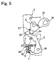
- Fig. 5 illustrates a state of contact between the rectilinear portion of a clincher link and the cam in case a bundle of sheets is thin;
- Fig. 6 is a partial perspective view showing schematically in what state a driver, an anvil and a forming plate are arranged;
- Fig. 7 is a plan view of the driver;
- Fig. 8 is a plan view of the forming plate; and
- Fig. 9 is an explanatory diagram showing a positional concept in section of a staple which is formed into a predetermined shape by the driver, forming plate and anvil.
-
- A motor-operated stapler embodying the present invention will be described hereinunder with reference to the accompanying drawings.
- Fig. 1 illustrates the configuration of a principal mechanism for driving clinchers in the motor-operated stapler which is indicated at 1. In the same figure, the reference numeral 2 denotes a magazine, the
numeral 3 denotes a clincher base, numeral 4 denotes a clincher,numeral 5 denotes a clincher link, numeral 6 denotes a driving cam, andnumeral 7 denotes a bundle of sheets to be stapled. - The motor-operated stapler 1 is also provided with other mechanisms than the mechanism shown in Fig. 1, such as a control unit and a driver motor, but a principal mechanism for driving clinchers is shown in Fig. 1.
- The magazine 2 has a
cartridge 10 which receives therein a large number of joinedstaple members 9 in a stacked state, the joinedstaple members 9 each comprising straight wire-like staples 11 which are joined together in the shape of sheet, and a well known feeding means which send out the joinedstaple members 9 for each staple thickness, i.e., staple by staple, from thecartridge 10 and adriver 12 which drives out each staple 6 thus sent out into the bundle ofsheets 7 after the staple has been bent in U shape by a formingplate 14. - Each joined
staple member 9 comprises, say, one hundred wire-like staples 11 arranged in parallel and joined together with an adhesive so as to be separable one by one using thedriver 12. - The interior of the
cartridge 10 is formed so as to permit a large number of the joinedstaple members 9 to be accommodated therein in a stacked state and also permit the joinedstaple members 9 to be sent out staple by staple leftwards in Fig. 1(B) from a lower portion of thecartridge 10. - The
driver 12 is for causing eachU-shaped staple 11 to pierce into the bundle ofsheets 7. For bending each wire-like staple 11 in U shape, as shown in Figs. 6 to 9, there are provided ananvil 13 which supports thestaple 11 and the formingplate 14 which bends both sides of the staple into U shape while the staple is carried on theanvil 13. - The
driver 12 and the formingplate 14 are integrally superimposed one on the other in a front and rear relation to each other and are adapted to move together vertically. - More specifically, as shown in Fig. 8, the forming
plate 14 has arecess 14A for forming both sides of the wire-like staple 11 into U shape, thestaple 11 being supported by theanvil 13. Thedriver 12, as shown in Fig. 7, has aconvex portion 12A for driving out thestaple 11 thus formed in U shape into the bundle ofsheets 7. - As shown in Figs. 6 and 9, when the forming
plate 14 is forming both sides of astaple 11 on theanvil 13 into U shape, thedriver 12 is driving out anotherstaple 11 which has already been formed in U shape into the bundle ofsheets 7. When the formingplate 14 and thedriver 12 have completed their forming and drive-out operations and move from a bottom dead center position to a top dead center position,leg portions 11A of thestaple 11 which has been formed in U shape by the formingplate 14 are pushed with pushers (not shown) positioned on both sides of theanvil 13 and are abutted against a stopper plate 14B in a connected state to the joinedstaple member 9, the stopper plate 14B forming a front wall of a staple drive-out passage. - When the
driver 12 and the formingplate 14 are retracted above thestaple 11, thestaple 11 which has been formed in U shape is in abutment against the stopper plate 14B in a connected state to the joinedstaple member 9. - As the
driver 12 and the formingplate 14 move down, thestaple 11 which has been formed in U shape is pushed by thedriver 12 and is separated from the joinedstapler member 9 and theleg portions 11A of thestaple 11 begin to pierce through the bundle ofsheets 7. At the same time, leg portions 11'A of a staple 11' which follows next begin to be formed in U shape by the formingplate 14. - When the
driver 12 has driven out a U shapedstaple 11 completely into the bundle ofsheets 7, the formingplate 14 has completed its work of forming the leg portions 11'A of the next staple 11' into U shape. - When the
driver 12 drives out thestaple 11 into the bundle ofsheets 7, upper surfaces of the paired clinchers 4 respectively face the positions of dot-dash lines B in Fig. 1. - The
clincher base 3 is held vertically movably by a chassis (not shown) of the motor-operated stapler which chassis holds the magazine 2, and it is driven by a drive mechanism and a control unit both mounted to the chassis. As shown in Fig. 1(B), the drive mechanism is made up of a motor M and a gear mechanism G, while the control unit is composed of a microcomputer and a peripheral circuit connected to the microcomputer. - Near the
clincher base 3 of the motor-operated stapler there is disposed a sensor for detecting that the bundle ofsheets 7 has been fed. For example, the said sensor is constituted by a microswitch or an optical sensor. When the sensor detects that the bundle ofsheets 7 has been put on a table 3A of theclincher base 3, the drive mechanism is operated through the control unit, whereby theclincher base 3 is moved upward and holds the bundle ofsheets 7 between it and the magazine 2. - The thickness of the bundle of
sheets 7 inserted between the table 3A of theclincher base 3 and the magazine 2 is set beforehand to a thickness which permits the bundle to be stapled by eachstaple 11. As a sensor for judging whether the thickness of the bundle ofsheets 7 permits the bundle to be stapled or not, a microswitch for example is disposed within the area of movement of theclincher base 3. - For example, in the area of upper movement of the
clincher base 3 is disposed a microswitch which determines an upper limit value in thickness of the bundle ofsheets 7 when theclincher base 3 holds the bundle ofsheets 7 between it and the magazine 2. When the microswitch detects that the thickness of the bundle ofsheets 7 has exceeded the upper limit value, it sends the detected signal to the control unit. - In the case where the thickness of the bundle of
sheets 7 is a thickness at which the bundle cannot be stapled by thestaple 11, this state is detected, for example, by a sensor which detects the amount of movement of theclincher base 3 and the detected aignal is outputted to the control unit. The control unit inhibits thedriver 12 from driving out thestaple 11, causes the clincher base-3 to move down, thereby releasing the bundle ofsheets 7, and further causes display means, e.g., a liquid crystal display, to make a display that stapling is not performed. - As shown in Figs. 2(A) and 2(B), both ends of a
front end portion 15 of theclincher base 3 toward which the bundle ofsheets 7 is inserted are integral with L-shapedside plate portions 16 respectively. Thefront end portion 15 of theclincher base 3 is formed substantially in the shape of a flat plate, andspacers 17 which support the clinchers 4 are attached to the back of thefront end portion 15 of theclincher base 3. - A table 3A whose front end is bent downward is fixed with screws to the
clincher base 3 at a position where the bundle ofsheets 7 is rested. In the table 3A, which is for carrying the bundle ofsheets 7 thereon, there is formed anopening 3B permitting vertical movements of the paired clinchers 4. Theopening 3B permits the clinchers 4 pass therethrough for bending the leg portions of each staple 11 in parallel with the back sheet of thebundle 7. - The pair of clinchers 4 are pivotably held respectively with
pins 17A of thespacers 17 and are pulled downward from chord springs (not shown). Upper surfaces of the clinchers 4 face the positions of dot-dash lines B in Fig. 1. - The clincher links 5 are respectively supported by pins 18 (fulcrums) provided respectively on the right and left
side plate portions 16 of theclincher base 3. The clincher links 5 each have a generally L-shaped side shape. At a lower end portion of eachclincher Link 5 is formed acam plate portion 19 which is bent at nearly right angles from the clincher link. The cam plate portion of eachclincher link 5 is inserted into a recess 4A of the associated clincher 4, whereby a pivotal motion of theclincher link 5 is transmitted to the clincher 4. - As shown in Figs. 1(B), 4 and 5, an upper portion of each
clincher link 5 is formed with an abutting portion 20 (a driven cam surface) for abutment therewith of the driving cam 6 with a vertical movement of theclincher base 3. With the abuttingportions 20 of the pairedclincher links 5, rotation of the driving cams 6 causes a pivotal motion of the clinchers 4 no matter how thick the bundle ofsheets 7 may be. - An upper part of the abutting
portion 20 is an area with which the driving cam 6 comes into contact when the bundle ofsheets 7 is thick, and an auxiliary projection 21 is formed on the upper part of the abuttingportion 20. The abuttingportion 20 and the auxiliary projection 21 constitute clincher's pivotal movement control means. - The auxiliary projection 21 is for obtaining the same amount of pivotal movement of each clincher 4 as that in case of the bundle of
sheet 7 being thin even when the bundle is thick, and causes the leg portions of each staple 11 to be bent along the bundle ofsheets 7 in the same manner as in case of the bundle being thin even when the staple leg portions are short. - Each driving cam 6 is held with a
pin 23 fixed to the chassis (fixing member, not shown) of the motor-operated stapler 1 which chassis holds and fixes the magazine 2, and is rotated by acam 22. - A
cylindrical shaft 24 is mounted to the driving cam 6 at a position at which the driving cam comes into contact with the abuttingportion 20. When the driving cam 6 is rotated, theshaft 24 pushes the abuttingportion 20, causing the associatedclincher link 5 to turn. - The
cam 22 which causes the driving cam 6 to rotate is fixed with apin 25. Thepin 25 is driven through a drive motor and a reduction mechanism (neither shown) installed in the motor-operated stapler 1. - In the motor-operated stapler 1 of this embodiment constructed as above, when the bundle of
sheets 7 is carried onto theclincher base 3, the control unit and the drive mechanism both installed in the stapler 1 operate and theclincher base 3 approaches the magazine 2 until the magazine 2 and theclincher base 3 eventually pinch and hold the bundle ofsheets 7 therebetween. - When the bundle of
sheets 7 is held, the position of the clincher base 8 varies vertically according to the thickness of the sheets bundle, but since the abuttingportions 20 of theclincher links 5 are formed correspondingly to the thickness of the sheets bundle 7, the driving cams 6 come into contact with theclincher links 5 at a nearly constant angle, so even upon rotation thereof the amount of pivotal movement of the clincher links 5 does not change according to the thickness of the sheets bundle 7, so that the clinchers 4 which pivot in accordance with the pivotal movement of theclincher links 5 are always constant in the amount of their pivotal motion. Thus, theleg portions 11A of each staple 11 can be bent always in a constant state. - Thus, even if the thickness of the sheets bundle 7 varies, the magazine 2 and the
clincher base 3 can hold the bundle therebetween. - When stapling of the sheets bundle 7 is permitted, the driving cams 6 rotate and the
shafts 24 thereof push the abuttingportions 20 of theclincher links 5, thus causing theclincher links 5 to turn. - When the
clincher links 5 thus turn, the clinchers 4 move pivotally along the bundle ofsheets 7, causing the leg portions of the staple 11 projecting from the sheets bundle to be bent along the back of the bundle. - After the leg portions of the staple 11 have thus been bent, the
clincher links 5 revert to their original stand-by positions and the clinchers 4 turn below the table 3A, as is seen from the cam surface shape of the driving cams 6. Further, theclincher base 3 is retracted from the magazine 2 and the sheets bundle 7 thus stapled is released. The sheets bundle 7 thus released is then sent to a stack tray by feed rollers of a copying machine on which the motor-operated stapler 1 is mounted. - At an upper end of each abutting
portion 20 in theclincher base 3 is formed the auxiliary projection 21 as clincher's pivotal movement control means to keep the pivotal movement of the associatedclincher link 5 constant no matter at which position the driving cam 6 may be abutted against the abuttingportion 20. - Although in the above embodiment the clincher's pivotal movement control means is constituted by the abutting
portion 20 and the auxiliary projection 21, no limitation is made thereto. As clincher's pivotal movement control means, acurved surface 20A (see Fig. 4(B)) which projects gently toward the driving cam 6, or an inclined surface 20B (see Fig. 4(C)), may be formed as a guide surface above the abuttingportion 20, and both this guide surface and the abuttingportion 20 may constitute the clincher's pivotal movement control means. - Further, as clincher's pivotal movement control means, in order that the position of the auxiliary projection 21 can be changed, a driven cam provided with the auxiliary projection 21 may be provided separately on each
clincher link 5 side so as to be vertically adjustable by an adjusting lever with use of a link mechanism or the like. - According to the motor-operated stapler in one aspect of the present invention, as set forth above, as the clincher base which carries a bundle of sheets thereon approaches the magazine, the bundle of sheets is pinched and held between the magazine and the clincher base.
- Even if the thickness of the sheets bundle differs, since the driven cam surface of each clincher link extends in the thickness direction of the sheets bundle, the bundle can be pinched and held between the magazine and the clincher base irrespective of the sheets bundle thickness.
- Further, after the bundle of sheets has thus been pinched, the driving cams provided on the magazine side are rotated, whereby the clincher links move pivotally and bend leg portions of a staple projecting from the bundle of sheets.
- In the case of a thick bundle of sheets, the distance between the abutting point of each driving cam against the associated clincher link and the pivotal fulcrum of the clincher link becomes long, but since the clincher link is provided with pivotal movement control means, the same amount of pivotal movement as in the case of a thin bundle of sheets is ensured, so that a pair of leg portions projecting from the bundle of sheets can be bent along the back of the sheets bundle and thus even a thick bundle of sheets can be prevented from coming off the staple.
- According to the motor-operated stapler in the second aspect of the present invention, since a projection for further bending the leg portions of a staple in the case of a thick sheets bundle is formed within the driven cam surface, there is no increase in the number of components and there can be attained a simple configuration and a low cost.
- According to the motor-operated stapler in the third aspect of the present invention, by constituting a link mechanism in such a manner that even when the thickness of a bundle of sheets is larger than a predetermined value with respect to the length of leg portions of a staple, there is ensured the same amount of pivotal movement of each clincher as in the case of a thin sheets bundle, staple leg portions projecting from the bundle of sheets can be bent along the back of the bundle even if the bundle is thick.
- Thus, according to the first to third aspects of the present invention, in a motor-operated stapler of the type wherein a clincher base which pinches and holds a bundle of sheets in cooperation with a magazine is held on the magazine side and clincher links are pivotally moved by means of a drive source provided on the magazine side, even when the distance between an abutting point of each clincher link against a driving cam and a pivotal fulcrum varies depending on the thickness of a sheets bundle, staple leg portions projecting from the underside of the sheets bundle can be bent at a predetermined certain angle. Therefore, staple leg portions are prevented from being bent to excess and again piercing through the bundle of sheets, while in the case of a thick bundle of sheets, staple leg portions can be bent to a sufficient degree, whereby the bundle of sheets can be prevented from coming off the staple leg portions.
Claims (3)
- A motor-operated stapler wherein a bundle of sheets to be stapled is held by both a magazine which houses therein a staple forming mechanism and a plurality of staples and a clincher base which is movable in the thickness direction of the bundle of sheets and which is driven by a drive source provided on the magazine side, a staple is driven out from said magazine into said bundle of sheets, and leg portions of the staple projecting downward from said bundle of sheets are bent along said bundle of sheets by a pair of clinchers mounted on said clincher base,
characterized by including clinchers' pivotal movement control means which keeps the amount of pivotal movement of said clinchers constant irrespective of the thickness of said bundle of sheets. - A motor-operated stapler according to claim 1, further including:a clincher pivoting mechanism for moving said clinchers pivotally, said clincher pivoting mechanism comprising clincher links installed on said clincher base to move said clinchers vertically pivotally, driven cam surfaces formed respectively on said clincher links and extending in the thickness direction of said bundle of sheets to be stapled, fulcrums which convert swing motions of said cam surfaces into pivotal motions of said clinchers, and driving cams installed on fixing means side which hold said magazine, said driving cams coming into contact with said driven cam surfaces of the clincher links and being rotated by said drive source provided on the magazine side, andwherein said clinchers' pivotal movement control means are formed respectively in upper areas of said driven cam surfaces with which said driving cams come into contact and are constituted respectively by projections for causing said clinchers to further turn in a direction to approach the surface of said bundle of sheets.
- A motor-operated stapler according to claim 1, further including a clincher pivoting mechanism for moving said clinchers pivotally, said clincher pivoting mechanism comprising clincher links installed on said clincher base to move said clinchers vertically pivotally, driven cam surfaces formed respectively on said clincher links and extending in the thickness direction of said bundle of sheets to be stapled, fulcrums which convert swing motions of said driven cam surfaces into pivotal motions of said clinchers, and driving cams installed on fixing means side which hold said magazine, said driving cams coming into contact with said driven cam surfaces of the clincher links and being rotated by said drive source provided on the magazine side, and
wherein said clinchers' pivotal movement control means are constructed so that when the thickness of said bundle of sheets exceeds a predetermined value with respect to the length of staple leg portions, the distance between an abutment position and each of said fulcrums which abutment position is the position of abutment between each of said clincher links and each of said clinchers is increased relatively with respect to the distance between an abutment position and each of said fulcrums which abutment position is the position of abutment between each of said clincher links and each of said driving cams.
Applications Claiming Priority (4)
| Application Number | Priority Date | Filing Date | Title |
|---|---|---|---|
| JP2000164272 | 2000-06-01 | ||
| JP2000164272 | 2000-06-01 | ||
| JP2001144253A JP4644973B2 (en) | 2000-06-01 | 2001-05-15 | Electric stapler |
| JP2001144253 | 2001-05-15 |
Publications (2)
| Publication Number | Publication Date |
|---|---|
| EP1160063A1 true EP1160063A1 (en) | 2001-12-05 |
| EP1160063B1 EP1160063B1 (en) | 2008-03-19 |
Family
ID=26593151
Family Applications (1)
| Application Number | Title | Priority Date | Filing Date |
|---|---|---|---|
| EP01250195A Expired - Lifetime EP1160063B1 (en) | 2000-06-01 | 2001-05-31 | Motor-operated stapler |
Country Status (4)
| Country | Link |
|---|---|
| US (1) | US6698640B2 (en) |
| EP (1) | EP1160063B1 (en) |
| JP (1) | JP4644973B2 (en) |
| DE (1) | DE60133240T2 (en) |
Cited By (3)
| Publication number | Priority date | Publication date | Assignee | Title |
|---|---|---|---|---|
| EP1649991A4 (en) * | 2003-08-01 | 2008-07-16 | Max Co Ltd | Staple leg-bending mechanism |
| EP1704968A4 (en) * | 2004-01-13 | 2008-08-13 | Max Co Ltd | STAPLER |
| EP1795306A4 (en) * | 2004-09-29 | 2009-11-11 | Max Co Ltd | STAPLER |
Families Citing this family (31)
| Publication number | Priority date | Publication date | Assignee | Title |
|---|---|---|---|---|
| JP4228828B2 (en) * | 2003-08-01 | 2009-02-25 | マックス株式会社 | Stapler |
| JP4103724B2 (en) * | 2003-08-11 | 2008-06-18 | マックス株式会社 | Lock mechanism of paper presser table in stapler |
| US6981627B2 (en) * | 2004-04-21 | 2006-01-03 | Apex Mfg. Co., Ltd. | Electric stapler having an apparatus to bend staple legs and the apparatus |
| US7631822B2 (en) * | 2004-09-10 | 2009-12-15 | Fellowes Inc. | Shredder with thickness detector |
| US8870106B2 (en) * | 2004-09-10 | 2014-10-28 | Fellowes, Inc. | Shredder with thickness detector |
| US7661614B2 (en) * | 2004-09-10 | 2010-02-16 | Fellowes Inc. | Shredder throat safety system |
| US7954737B2 (en) | 2007-10-04 | 2011-06-07 | Fellowes, Inc. | Shredder thickness with anti-jitter feature |
| US7798435B2 (en) * | 2006-03-22 | 2010-09-21 | Fellowes, Inc. | Shredder with oiling mechanism |
| US6981626B1 (en) * | 2004-12-08 | 2006-01-03 | Apex Mfg. Co., Ltd. | Stapler with a leg-cutting device |
| US7334716B2 (en) * | 2005-01-26 | 2008-02-26 | Apex Mfg. Co., Ltd. | Stapler capable of cutting staple legs one after another |
| US7159749B2 (en) * | 2005-05-31 | 2007-01-09 | Apex Mfg. Co., Ltd. | Stapler capable of cutting staple legs |
| US7124926B1 (en) | 2005-06-09 | 2006-10-24 | Apex Mfg. Co., Ltd. | Stapler capable of cutting staple legs |
| US8672247B2 (en) | 2005-07-11 | 2014-03-18 | Fellowes, Inc. | Shredder with thickness detector |
| US20070023474A1 (en) * | 2005-07-14 | 2007-02-01 | Smith Robert S | Clincher for a heavy duty stapler |
| GB2437594B (en) * | 2006-04-24 | 2010-08-11 | Acco Uk Ltd | A shredding machine |
| GB2451513B (en) | 2007-08-02 | 2012-04-18 | Acco Uk Ltd | A shredding machine |
| JP5282565B2 (en) | 2008-12-25 | 2013-09-04 | マックス株式会社 | Through-load reduction staple |
| US8430347B2 (en) * | 2009-01-05 | 2013-04-30 | Fellowes, Inc. | Thickness adjusted motor controller |
| US8201761B2 (en) | 2009-01-05 | 2012-06-19 | Fellowes, Inc. | Thickness sensor based motor controller |
| US8091809B2 (en) * | 2009-03-24 | 2012-01-10 | Fellowes, Inc. | Shredder with jam proof system |
| US8205815B2 (en) * | 2009-05-15 | 2012-06-26 | Fellowes, Inc. | Paper alignment sensor arrangement |
| EP2255935B1 (en) * | 2009-05-28 | 2012-06-20 | Max Co., Ltd. | Electric stapler |
| US8678305B2 (en) * | 2009-06-18 | 2014-03-25 | Fellowes, Inc. | Restrictive throat mechanism for paper shredders |
| US8550387B2 (en) * | 2009-06-18 | 2013-10-08 | Tai Hoon K. Matlin | Restrictive throat mechanism for paper shredders |
| US8382019B2 (en) | 2010-05-03 | 2013-02-26 | Fellowes, Inc. | In-rush current jam proof sensor control |
| US8511593B2 (en) | 2010-05-28 | 2013-08-20 | Fellowes, Inc. | Differential jam proof sensor for a shredder |
| US20130240594A1 (en) * | 2012-03-19 | 2013-09-19 | Stanley Fastening Systems, L.P. | Cordless carton closer |
| JP6040746B2 (en) | 2012-12-12 | 2016-12-07 | マックス株式会社 | Stapler |
| US10786892B2 (en) * | 2015-11-30 | 2020-09-29 | Uchida Yoko Global Limited | Stapling device |
| JP6645339B2 (en) * | 2016-04-22 | 2020-02-14 | マックス株式会社 | Stapler |
| JP7251105B2 (en) * | 2018-11-02 | 2023-04-04 | マックス株式会社 | stapler |
Citations (4)
| Publication number | Priority date | Publication date | Assignee | Title |
|---|---|---|---|---|
| US5141143A (en) * | 1990-06-27 | 1992-08-25 | Eastman Kodak Company | Sheet-stapling device |
| US5385287A (en) * | 1993-02-06 | 1995-01-31 | Eastman Kodak Company | Sheet-stapling device |
| EP0838315A2 (en) * | 1996-10-23 | 1998-04-29 | Max Co., Ltd. | Electric stapler |
| US5806750A (en) * | 1995-11-16 | 1998-09-15 | Nisca Corporation | Automatic stapling device |
Family Cites Families (12)
| Publication number | Priority date | Publication date | Assignee | Title |
|---|---|---|---|---|
| US1169339A (en) * | 1915-06-30 | 1916-01-25 | Boston Wire Stitcher Co | Stapling-machine. |
| US1852060A (en) * | 1929-02-09 | 1932-04-05 | Hotchkiss Co E H | Desk stapling machine |
| JPS53119145A (en) * | 1977-03-25 | 1978-10-18 | Yoshida Kogyo Kk | Structure of clamp of slide zipper |
| MX149500A (en) * | 1978-12-29 | 1983-11-15 | Xerox Corp | IMPROVEMENTS IN WIRE SEAMERS TO BIND SHEET SETS |
| US4358040A (en) * | 1979-04-27 | 1982-11-09 | Xerox Corporation | Stitchers |
| US5238169A (en) * | 1990-10-29 | 1993-08-24 | Mato Maschinen-Und Metallwarenfabrik Curt Matthaei Gmbh & Co Kg | Apparatus for fastening belt ends |
| CA2108807A1 (en) * | 1992-11-13 | 1994-05-14 | Roman M. Golicz | Power stapler |
| DE4331783A1 (en) * | 1993-09-18 | 1995-03-23 | Prym William Gmbh & Co Kg | Machine for attaching buttons, rivets or the like, preferably to clothing |
| JP3526682B2 (en) * | 1995-12-13 | 2004-05-17 | マックス株式会社 | Electric stapler |
| US5791543A (en) * | 1995-12-11 | 1998-08-11 | Max Co., Ltd. | Electric stapler |
| DE19607296A1 (en) * | 1996-02-27 | 1997-08-28 | Kodak Ag | Stitching device for fastening stack-shaped sheets |
| JP3344455B2 (en) * | 1996-10-25 | 2002-11-11 | マックス株式会社 | Clinch mechanism in stapler |
-
2001
- 2001-05-15 JP JP2001144253A patent/JP4644973B2/en not_active Expired - Lifetime
- 2001-05-31 DE DE60133240T patent/DE60133240T2/en not_active Expired - Lifetime
- 2001-05-31 EP EP01250195A patent/EP1160063B1/en not_active Expired - Lifetime
- 2001-06-01 US US09/873,165 patent/US6698640B2/en not_active Expired - Lifetime
Patent Citations (4)
| Publication number | Priority date | Publication date | Assignee | Title |
|---|---|---|---|---|
| US5141143A (en) * | 1990-06-27 | 1992-08-25 | Eastman Kodak Company | Sheet-stapling device |
| US5385287A (en) * | 1993-02-06 | 1995-01-31 | Eastman Kodak Company | Sheet-stapling device |
| US5806750A (en) * | 1995-11-16 | 1998-09-15 | Nisca Corporation | Automatic stapling device |
| EP0838315A2 (en) * | 1996-10-23 | 1998-04-29 | Max Co., Ltd. | Electric stapler |
Cited By (6)
| Publication number | Priority date | Publication date | Assignee | Title |
|---|---|---|---|---|
| EP1649991A4 (en) * | 2003-08-01 | 2008-07-16 | Max Co Ltd | Staple leg-bending mechanism |
| EP1704968A4 (en) * | 2004-01-13 | 2008-08-13 | Max Co Ltd | STAPLER |
| US7922060B2 (en) | 2004-01-13 | 2011-04-12 | Max Co., Ltd. | Stapler |
| US8348121B2 (en) | 2004-01-13 | 2013-01-08 | Max Co., Ltd. | Stapler |
| EP1795306A4 (en) * | 2004-09-29 | 2009-11-11 | Max Co Ltd | STAPLER |
| US7681770B2 (en) | 2004-09-29 | 2010-03-23 | Max Co., Ltd. | Stapler |
Also Published As
| Publication number | Publication date |
|---|---|
| DE60133240T2 (en) | 2009-04-30 |
| US6698640B2 (en) | 2004-03-02 |
| DE60133240D1 (en) | 2008-04-30 |
| US20010050302A1 (en) | 2001-12-13 |
| JP2002052482A (en) | 2002-02-19 |
| EP1160063B1 (en) | 2008-03-19 |
| JP4644973B2 (en) | 2011-03-09 |
Similar Documents
| Publication | Publication Date | Title |
|---|---|---|
| US6698640B2 (en) | Motor operated stapler | |
| US5346114A (en) | Electric stapler with unmovably fixed magazine | |
| JP5359694B2 (en) | Stapler clincher mechanism | |
| WO2003022538A1 (en) | Staple detection mechanism of electric stapler | |
| US5460314A (en) | Stapler with improved stapling precision | |
| EP0475436B1 (en) | Electric stapler with unmovably fixed magazine | |
| AU2004315246B9 (en) | Stapler | |
| EP1736282A1 (en) | Stapler | |
| EP1129832B1 (en) | Sheet post processing apparatus | |
| CN1413139A (en) | Stapler with reversible electric motor | |
| JP2001269903A (en) | Electric stapler | |
| US6547238B2 (en) | Sheet beam breaker | |
| JP2024092214A (en) | Stapler | |
| US20010011667A1 (en) | Stapling device | |
| JP7251105B2 (en) | stapler | |
| EP1649991A1 (en) | Staple leg-bending mechanism | |
| JP3489352B2 (en) | Clamping device | |
| JPH04129680A (en) | Magazine fixing type motor-driven stapler | |
| WO2007055398A1 (en) | Desktop machine with a paper support | |
| JPH058580A (en) | Sheet binding device | |
| EP1749619A1 (en) | Clincher device for stapler | |
| JP2006116638A (en) | Clinch device of motor-driven stapler | |
| JP2663799B2 (en) | Staple feeding device for electric stapler | |
| JP2024015983A (en) | Sheet processing equipment and image forming system | |
| JPH0551577U (en) | Electric stapler |
Legal Events
| Date | Code | Title | Description |
|---|---|---|---|
| PUAI | Public reference made under article 153(3) epc to a published international application that has entered the european phase |
Free format text: ORIGINAL CODE: 0009012 |
|
| AK | Designated contracting states |
Kind code of ref document: A1 Designated state(s): DE FR GB NL SE Kind code of ref document: A1 Designated state(s): AT BE CH CY DE DK ES FI FR GB GR IE IT LI LU MC NL PT SE TR |
|
| AX | Request for extension of the european patent |
Free format text: AL;LT;LV;MK;RO;SI |
|
| 17P | Request for examination filed |
Effective date: 20020529 |
|
| AKX | Designation fees paid |
Free format text: DE FR GB NL |
|
| RBV | Designated contracting states (corrected) |
Designated state(s): DE FR GB NL SE |
|
| GRAP | Despatch of communication of intention to grant a patent |
Free format text: ORIGINAL CODE: EPIDOSNIGR1 |
|
| GRAS | Grant fee paid |
Free format text: ORIGINAL CODE: EPIDOSNIGR3 |
|
| GRAA | (expected) grant |
Free format text: ORIGINAL CODE: 0009210 |
|
| AK | Designated contracting states |
Kind code of ref document: B1 Designated state(s): DE FR GB NL SE |
|
| REG | Reference to a national code |
Ref country code: GB Ref legal event code: FG4D |
|
| REF | Corresponds to: |
Ref document number: 60133240 Country of ref document: DE Date of ref document: 20080430 Kind code of ref document: P |
|
| REG | Reference to a national code |
Ref country code: SE Ref legal event code: TRGR |
|
| ET | Fr: translation filed | ||
| PLBE | No opposition filed within time limit |
Free format text: ORIGINAL CODE: 0009261 |
|
| STAA | Information on the status of an ep patent application or granted ep patent |
Free format text: STATUS: NO OPPOSITION FILED WITHIN TIME LIMIT |
|
| 26N | No opposition filed |
Effective date: 20081222 |
|
| REG | Reference to a national code |
Ref country code: FR Ref legal event code: PLFP Year of fee payment: 16 |
|
| REG | Reference to a national code |
Ref country code: FR Ref legal event code: PLFP Year of fee payment: 17 |
|
| PGFP | Annual fee paid to national office [announced via postgrant information from national office to epo] |
Ref country code: NL Payment date: 20170412 Year of fee payment: 17 |
|
| PGFP | Annual fee paid to national office [announced via postgrant information from national office to epo] |
Ref country code: GB Payment date: 20170531 Year of fee payment: 17 Ref country code: FR Payment date: 20170413 Year of fee payment: 17 |
|
| PGFP | Annual fee paid to national office [announced via postgrant information from national office to epo] |
Ref country code: SE Payment date: 20170511 Year of fee payment: 17 |
|
| REG | Reference to a national code |
Ref country code: NL Ref legal event code: MM Effective date: 20180601 |
|
| REG | Reference to a national code |
Ref country code: SE Ref legal event code: EUG |
|
| GBPC | Gb: european patent ceased through non-payment of renewal fee |
Effective date: 20180531 |
|
| PG25 | Lapsed in a contracting state [announced via postgrant information from national office to epo] |
Ref country code: SE Free format text: LAPSE BECAUSE OF NON-PAYMENT OF DUE FEES Effective date: 20180601 |
|
| PG25 | Lapsed in a contracting state [announced via postgrant information from national office to epo] |
Ref country code: NL Free format text: LAPSE BECAUSE OF NON-PAYMENT OF DUE FEES Effective date: 20180601 Ref country code: FR Free format text: LAPSE BECAUSE OF NON-PAYMENT OF DUE FEES Effective date: 20180531 Ref country code: GB Free format text: LAPSE BECAUSE OF NON-PAYMENT OF DUE FEES Effective date: 20180531 |
|
| PGFP | Annual fee paid to national office [announced via postgrant information from national office to epo] |
Ref country code: DE Payment date: 20200519 Year of fee payment: 20 |
|
| REG | Reference to a national code |
Ref country code: DE Ref legal event code: R071 Ref document number: 60133240 Country of ref document: DE |