EP1158824A2 - Control technique for a communication system - Google Patents
Control technique for a communication system Download PDFInfo
- Publication number
- EP1158824A2 EP1158824A2 EP01304255A EP01304255A EP1158824A2 EP 1158824 A2 EP1158824 A2 EP 1158824A2 EP 01304255 A EP01304255 A EP 01304255A EP 01304255 A EP01304255 A EP 01304255A EP 1158824 A2 EP1158824 A2 EP 1158824A2
- Authority
- EP
- European Patent Office
- Prior art keywords
- base station
- microcell
- macrocell
- dimensional
- steerable
- Prior art date
- Legal status (The legal status is an assumption and is not a legal conclusion. Google has not performed a legal analysis and makes no representation as to the accuracy of the status listed.)
- Granted
Links
Images







Classifications
-
- H—ELECTRICITY
- H04—ELECTRIC COMMUNICATION TECHNIQUE
- H04W—WIRELESS COMMUNICATION NETWORKS
- H04W16/00—Network planning, e.g. coverage or traffic planning tools; Network deployment, e.g. resource partitioning or cells structures
- H04W16/24—Cell structures
- H04W16/32—Hierarchical cell structures
Definitions
- the present invention relates to a control technique for a communication system, and more particularly, to a control technique for a wireless communication system.
- FIG. 1 illustrates an example of a macrocell 10 served by a basestation 20 including two hot spots 30.
- microcells may be established for thoroughfares such as crossroads or streets, and a series of microcells may provide coverage for major traffic arteries such as highways.
- Microcells may also be assigned to large buildings, airports, and shopping malls.
- Picocells are similar to microcells, but normally cover an even smaller area, such as an office corridor or a floor of a high-rise building.
- microcell is used in this application to denote microcells, picocells, and any other "inner” layer of another cellular structure.
- macrocell is used in this application to denote the outermost layer of a cellular structure.
- An “umbrella cell” can be a macrocell or a microcell as long as there is a cell underlying the umbrella cell. Microcells allow additional communication channels to be located in the vicinity of actual need, thereby increasing cell capacity while maintaining low levels of maintenance.
- Macrocell umbrella sites typically cover radii in excess of 1 kilometer and serve rapidly moving users, for example people in automobiles.
- Each microcell site is usually served by a separate low power, small radio base station, with its own antenna that is located within the microcell and which primarily handles slow moving users such as pedestrians.
- Each microcell site is connected to a macrocell site through a transmission medium, such as digital radio transmission or optical fibers.
- Microcells suffer from a series of problems, including an increased sensitivity to traffic variations, interference between microcells, and difficulty in anticipating traffic intensities.
- microcells are a way of increasing capacity still further.
- base station antennas are placed below the building height in urban areas, and low power is used such that the propagation characteristics between base station and mobile are dominated by the street layout. Interference from adjacent cells may be blocked by buildings.
- Microcellular techniques allow significantly higher traffic densities to be achieved, and also enable smaller, lower power mobiles to be used.
- the use of microcells requires improved handover, i.e., handoff, techniques, which allow for fast and reliable handoff, for example when turning a street corner.
- handover i.e., handoff
- One way of easing handover problems is to employ an "umbrella cell" arrangement using conventional cells overlaying the microcells such that handover can be made into the umbrella cell where no suitable adjacent microcell can be identified. This also avoids the need to plan a contiguous microcell coverage in an urban area.
- the current solution for dealing with the hot spot problem illustrated in Figure 1 is to create microcells within the macro-cells, i.e., to introduce hierarchy in the cell. As illustrated on Figure 2, two microcells 40 are formed at the two hot spots 30.
- the macrocell 10 acts as the umbrella cell.
- Such a solution requires installing basestations 20' in each hot spot coverage area, which is costly.
- this solution assumes that the hot spots 30 do not move with time.
- the present invention provides a novel communication management technique for systems including microcells, which reduces the problems described above with conventional communication systems including microcells.
- the principle of the present invention solves the above-identified problem by co-locating the microcell antenna with the macrocell antenna.
- the microcell basestation utilizes a two-dimensional (2D) antenna array, which is co-located with the macrocell antenna.
- the two-dimensional antenna array is steerable in both the horizontal and vertical directions.
- the size of the microcell coverage area depends upon the distance from the cell site antenna as well as the dimensionality of the array, which determines the angular spread of the beam.
- co-location may be defined as within 30 feet, or more preferably within 15 feet, or even more preferably within 5 feet, and even more preferably within 2 feet. “Co-located” may also be defined as on the same antenna tower regardless of distance separation.
- Filter tap weights may be adjusted to point the beam for the microcell to any desired location in the macrocell.
- the orthogonality between macrocell and the microcell may be obtained either in the frequency domain or in the code domain.
- separation may be in the frequency domain, whereas for CDMA systems, the separation may either be in the frequency domain or in the code domain.
- Figure 3 illustrates the present invention in one exemplary embodiment.
- macrocell 10 is served by basestation 200.
- the present invention identifies microcells 40 at the location of each of the hot spots 30.
- a two-dimensional array 50 is provided at the same location as the basestation 200 for each of the identified hot spots 30/microcells 40.
- Figure 3 only illustrates one of the two-dimensional arrays 50.
- Each two-dimensional array 50 performs three-dimensional beamforming to steer a microcell 40 to a desired location, namely, a hot spot 30.
- Each two-dimensional array 50 is steerable in both the horizontal and vertical directions.
- Figure 4 illustrates the relationship of the two-dimensional array 50 with the base station 200.
- Figure 4 illustrates at least two antenna elements 22, at least two radio frequency (RF) modules 24, at least two analog-digital converter/digital-analog converters (ADC/DAC) 26, two-dimensional digital multiplier/filter 27 for three-dimensional beamforming, conventional digital signal processing 28, and filter tap weights 52, 54.
- RF radio frequency
- ADC/DAC analog-digital converter/digital-analog converters
- ADC/DAC analog-digital converter/digital-analog converters
- the filter tap weights 52, 54 for each antenna element 22 may be adjusted to steer the beam 60 to any desired location in the macrocell 10. Examples of beam steering are illustrated in Figures 5(a) and 5(b). As illustrated in Figure 5(a), the tap weights w ij may be varied in a transmit mode, to point the beam from the base station 200 to a given hot spot 30 in the macrocell 10. In particular, the weights w 11 , w 12 , w 13 etc. steer the beam horizontally, in the xy plane and the weights w 11 , w 21 , w 31 etc. steer the beam vertically, in the z plane, as illustrated in Figure 5(a).
- the tap weights w ij may also be varied in a receive mode, to point the beam from a given hot spot 30 in the macrocell 10 to the base station 200.
- the weights w 11 , w 12 , w 13 etc. steer the beam horizontally, in the xy plane and the weights w 11 , w 21 , w 31 etc. steer the beam vertically in the z plane, as illustrated in Figure 5(b).
- Figure 6 illustrates base station 200 acting as a receiver and shows an example of spatial filtering when receiving a localized beam pattern in two dimensions.
- weighting coefficients W 1...N are utilized to weight the inputs from each of at least two antenna elements 22, which are then input to a summer 62 to produce a received signal as the array response.
- Figure 7 illustrates base station 200 acting as a transmitter.
- to localize the beam in the vertical (z) direction in addition to the azimuthal (xy) direction would require another set of taps for each of the N azimuthal branches. This additional set of taps is omitted from Figures 6 and 7 for clarity.
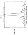
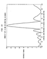
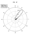
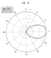
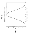
- the angular spread of the three-dimensional beam 60 can be varied by changing the number of taps 52, 54 in the two-dimensional array 50. More taps 52, 54 allow a narrower beam to be created; fewer taps produce a wider beam. Moreover, the "look direction" of the beam 60 can be changed via the tap weights as well. Once the number of taps is fixed, the beam can be steered in three dimensions.
- Figures 8-9 illustrates a 16 tap beam with a look direction of 0°.
- Figures 10-11 illustrate a 16 tap beam with a look direction of 30°.
- Figures 12-13 illustrate a 16 tap beam with a look direction of 50°.
- Figures 14-15 illustrate a 4 tap beam with a look direction of 0°.
- the two-dimensional arrays 50 may point the beam 60 any way in the macrocell 10 where the foot print of the beam 60 can also be varied. This flexibility offers tremendous capability in adapting to varying capacity needs in a macrocell.
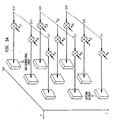
- the physical two-dimensional array of antennas can be either placed in a two-dimensional plane or on the surface of a cylinder or any other desirable configuration.
- the fundamental operation of the three-dimensional beamforming is not affected by the physical placement of the antenna elements in the array.
- Figure 16 illustrates the geometry of the elements 22 of the antenna array; in particular, Figure 16 illustrates an antenna array with N elements, at a spacing d, with a look direction of ⁇ .
- the incoming RF signal has a wavelength of ⁇ .
- Figure 17 illustrates the antenna array inputs to the beamformer.
- each antenna element 0, 1, ..., N-1, N receives an in-phase (I) and a quadrature (Q) component from the incoming RF signal.
- Each antenna element (0, 1, ..., N-1, N) also includes a weight (w 0 , w 1 , ... w N-1 , w N ).
- the complex coefficients for the K-th filter tap are given by:
- the 16 filter tap coefficients are: 1.0000 0.3593 + 0.9332i -0.7418 + 0.6706i -0.8923 + 0.4514i 0.1006 - 0.9949i 0.9646 - 0.2635i 0.5925 + 0.8056i -0.5389 + 0.8424i -0.9797 - 0.2003i -0.1651 - 0.9863i 0.8611 - 0.5084i 0.7839 + 0.6209i -0.2978 + 0.9546i -0.9979 + 0.0650i -0.4192 - 0.9079i 0.6967 - 0.7174i
- weights w 0 , w 1 , ..., w N-1 , w N which are applied to the antenna elements in Figure 17.
- the weights are multiplied with the in-phase (I) and quadrature (Q) elements received by each antenna element 22 to produce antenna element outputs. These outputs are summed in the beamformer to produce the I and Q beamformer output.
- the macrocell and microcell may be separated in frequency, by performing a dynamic frequency allocation between the microcell and the umbrella cell.
- this separation can be either in frequency or in the code domain.
- the antenna macrocell 10 is an omnidirectional antenna.
- the macrocell 10 could also be implemented utilizing an n-dimensional array (n ⁇ 1).
- the two-dimensional multiplier/filter 27 includes a plurality of multipliers.
- the two-dimensional multiplier/filter 27 may also include a space-time filter and therefore, also perform filtering and convolution.
- the present invention may be utilized in either a TDMA or CDMA system. However, the present invention may also be utilized in any number of communication systems.
Landscapes
- Engineering & Computer Science (AREA)
- Computer Networks & Wireless Communication (AREA)
- Signal Processing (AREA)
- Variable-Direction Aerials And Aerial Arrays (AREA)
- Mobile Radio Communication Systems (AREA)
- Radio Relay Systems (AREA)
- Radio Transmission System (AREA)
Abstract
Description

| 1.0000 |
| 0.3593 + 0.9332i |
| -0.7418 + 0.6706i |
| -0.8923 + 0.4514i |
| 0.1006 - 0.9949i |
| 0.9646 - 0.2635i |
| 0.5925 + 0.8056i |
| -0.5389 + 0.8424i |
| -0.9797 - 0.2003i |
| -0.1651 - 0.9863i |
| 0.8611 - 0.5084i |
| 0.7839 + 0.6209i |
| -0.2978 + 0.9546i |
| -0.9979 + 0.0650i |
| -0.4192 - 0.9079i |
| 0.6967 - 0.7174i |
Claims (26)
- A base station, servicing a macrocell, comprising:
at least one steerable N-dimensional (N≥2) array, co-located with an antenna of said base station, for serving a microcell within the macrocell. - The base station of claim 1, wherein said at least one steerable N-dimensional array serving the microcell is co-located on an antenna tower with the antenna serving the macrocell.
- The base station of claim 1, wherein the microcell includes a hot spot.
- The base station of claim 1, wherein said base station includes a steerable N-dimensional (N≥2) array for each microcell within the macrocell.
- The base station of claim 1, said at least one steerable N-dimensional array further including,
at least two antenna elements, and
an N-dimensional digital filter for receiving inputs from said at least two antenna elements and processing the inputs to produce a beamformed output. - The base station of claim 5, wherein at least one of inputs and outputs of said at least two antenna elements are weighted to steer a resultant output beam of said at least one steerable N-dimensional array.
- The base station of claim 6, wherein the at least one of inputs and outputs of said at least two antenna elements are weighted using variable filter tap weights.
- The base station of claim 1, wherein said at least one steerable N-dimensional (N≥2) array serves a hot spot.
- The base station of claim 6, wherein an angular spread and look direction of the resultant output beam of said at least one steerable N-dimensional array are varied by varying a number of filter taps.
- The base station of claim 5, wherein said at least two antenna elements are arranged in a two-dimensional plane or on a surface of a cylinder.
- The base station of claim 9, wherein complex coefficients for the filter taps are given by:where

- k=
- the filter tap,
- d=
- antenna element spacing,
- =
- look direction of the resultant output beam, and
- λ=
- wavelength of an incident signal.
- The base station of claim 1, wherein said base station is part of a TDMA system and the macrocell and the microcell are separated in the frequency domain.
- The base station of claim 1, wherein said base station is part of a CDMA system and the macrocell and the microcell are separated in one of the frequency and the code domains.
- A method of servicing at least one microcell in a macrocell, comprising:co-locating at least one steerable N-dimensional (N≥2) array with an antenna of said base station;steering a resultant beam of the at least one steerable N-dimensional (N≥2) array toward the at least one microcell.
- The method of claim 14, wherein said at least one steerable N-dimensional array serving the microcell is co-located on an antenna tower with the antenna serving the macrocell.
- The method of claim 14, wherein the microcell includes a hot spot.
- The method of claim 14, wherein said co-locating step includes co-locating a steerable N-dimensional (N≥2) array with the base station for each microcell within the macrocell.
- The method of claim 14, wherein the at least one steerable N-dimensional array includes at least two antenna elements and an N-dimensional digital filter for receiving inputs from the at least two antenna elements and processing the inputs to produce a beamformed output.
- The method of claim 18, further comprising weighting at least one of inputs and outputs of said at least two antenna elements to steer the resultant output beam of said at least one steerable N-dimensional array.
- The method of claim 19, wherein said weighting step includes weighting the at least one of inputs and outputs of the at least two antenna elements using variable filter tap weights
- The method of claim 14, wherein the at least one steerable N-dimensional array serves a hot spot.
- The method of claim 19, further comprising varying a number of filter taps of the resultant output beam of the at least one steerable N-dimensional array to vary an angular spread and look direction of the resultant output beam.
- The method of claim 18, further comprising arranging the at least two antenna elements in a two-dimensional plane or on a surface of a cylinder.
- The method of claim 22, wherein complex coefficients for the number of filter taps are given by:where

- k=
- the filter tap,
- d=
- antenna element spacing,
- =
- look direction of the resultant output beam, and
- λ=
- wavelength of an incident signal.
- The method of claim 14, wherein the base station is part of a TDMA system and the macrocell and the microcell are separated in the frequency domain.
- The method of claim 14, wherein the base station is part of a CDMA system and the macrocell and the microcell are separated in one of the frequency and the code domains.
Applications Claiming Priority (2)
| Application Number | Priority Date | Filing Date | Title |
|---|---|---|---|
| US09/576,999 US6950678B1 (en) | 2000-05-24 | 2000-05-24 | Control technique for a communication system |
| US576999 | 2000-05-24 |
Publications (3)
| Publication Number | Publication Date |
|---|---|
| EP1158824A2 true EP1158824A2 (en) | 2001-11-28 |
| EP1158824A3 EP1158824A3 (en) | 2002-02-13 |
| EP1158824B1 EP1158824B1 (en) | 2009-08-05 |
Family
ID=24306871
Family Applications (1)
| Application Number | Title | Priority Date | Filing Date |
|---|---|---|---|
| EP01304255A Expired - Lifetime EP1158824B1 (en) | 2000-05-24 | 2001-05-14 | Control technique for a communication system |
Country Status (9)
| Country | Link |
|---|---|
| US (1) | US6950678B1 (en) |
| EP (1) | EP1158824B1 (en) |
| JP (1) | JP5153037B2 (en) |
| KR (1) | KR100750820B1 (en) |
| CN (1) | CN1279768C (en) |
| AU (1) | AU4603801A (en) |
| BR (1) | BR0101967A (en) |
| CA (1) | CA2342411A1 (en) |
| DE (1) | DE60139440D1 (en) |
Cited By (7)
| Publication number | Priority date | Publication date | Assignee | Title |
|---|---|---|---|---|
| WO2006071154A1 (en) * | 2004-12-30 | 2006-07-06 | Telefonaktiebolaget Lm Ericsson (Publ) | An improved system for cellular radio coverage and an antenna for such a system |
| EP1791377A1 (en) * | 2005-11-23 | 2007-05-30 | Mitsubishi Electric Information Technology Centre Europe B.V. | Method for managing at least an area covered by a base station |
| EP2107637A1 (en) * | 2008-03-31 | 2009-10-07 | Ubidyne, Inc. | Antenna array and corresponding method for power loss compensation and suppression of sidelobes |
| EP2161956A1 (en) * | 2008-09-04 | 2010-03-10 | Alcatel, Lucent | Femto cell base station and method |
| WO2014083927A1 (en) * | 2012-11-28 | 2014-06-05 | ソニー株式会社 | Communication control device, communication control method, and terminal device |
| WO2017196675A3 (en) * | 2016-05-09 | 2018-01-11 | Cisco Technology, Inc. | Method and apparatus to optimally direct stations in macro-micro wireless cell |
| USRE47879E1 (en) | 2012-03-30 | 2020-02-25 | Samsung Electronics Co., Ltd. | Apparatus and method for channel-state-information pilot design for an advanced wireless network |
Families Citing this family (27)
| Publication number | Priority date | Publication date | Assignee | Title |
|---|---|---|---|---|
| SE523400C2 (en) * | 2001-11-30 | 2004-04-13 | Ericsson Telefon Ab L M | Cellular radio communication system utilizing wireless optical links and method of operating the system |
| CN101860876B (en) * | 2003-04-23 | 2015-07-29 | 意大利电信股份公司 | There is the wireless telephony network of multi-carrier packet data transmission |
| US8023951B2 (en) * | 2003-04-24 | 2011-09-20 | Nokia Siemens Networks Oy | Dynamic coverage and capacity solution for cellular radio network |
| KR101002126B1 (en) * | 2004-03-12 | 2010-12-16 | 주식회사 케이티 | Forward Power Control Method in Hierarchical Cell Environments of Wireless Communication Networks |
| JP4595379B2 (en) * | 2004-04-30 | 2010-12-08 | 日本電気株式会社 | Mobile communication service system and method |
| BRPI0512648B1 (en) * | 2004-09-07 | 2017-10-24 | Sunnen Products Company | AFFINITY ADVANCE SYSTEM INTEGRAL HAVING CONTROL OF THE FORCE, RATE AND ADVANCE POSITION, AND OPERATING PROCESS OF THE SAME |
| ES2439468T3 (en) * | 2005-03-31 | 2014-01-23 | Telecom Italia S.P.A. | Distributed antenna system |
| US20070213067A1 (en) * | 2006-03-09 | 2007-09-13 | Patrick Li | Wireless communication handoffs within a macrocell |
| EP2161783A1 (en) * | 2008-09-04 | 2010-03-10 | Alcatel Lucent | Method for multi-antenna signal processing at an antenna element arrangement, corresponding transceiver and corresponding antenna element arrangement |
| JP5373690B2 (en) * | 2010-04-16 | 2013-12-18 | パナソニック株式会社 | Communication system, main unit, radio access unit, and communication method |
| CN102378205B (en) * | 2010-08-13 | 2015-04-08 | 华为技术有限公司 | Method for creating micro-cell and base station |
| CN102387513A (en) * | 2010-08-31 | 2012-03-21 | 华为技术有限公司 | Micro cell creation method, micro base station and communication system |
| KR20120030200A (en) * | 2010-09-17 | 2012-03-28 | 주식회사 팬택 | Apparatus and method of transmitting data using multiple antenna and beam forming |
| CN102413478B (en) * | 2010-09-21 | 2015-12-02 | 华为技术有限公司 | Data transmission method and system |
| WO2011103821A2 (en) * | 2011-04-15 | 2011-09-01 | 华为技术有限公司 | Configuration method, device and system for picocells |
| KR101820733B1 (en) | 2011-08-24 | 2018-01-22 | 삼성전자주식회사 | Apparatus and method for selecting beam in wireless communication system |
| US8825064B2 (en) | 2011-08-31 | 2014-09-02 | At&T Mobility Llc | Femtocell measurements for merger integration planning |
| US8750896B2 (en) | 2011-10-13 | 2014-06-10 | At&T Mobility Ii Llc | Femtocell measurements for macro beam steering |
| US8811994B2 (en) * | 2011-12-06 | 2014-08-19 | At&T Mobility Ii Llc | Closed loop heterogeneous network for automatic cell planning |
| KR102087039B1 (en) * | 2013-01-18 | 2020-03-10 | 삼성전자 주식회사 | Method and apparatus for transmitting channel state information reference signal and hybrid spatial mutiplexing and space division multiple access for wireless communication system using planar antenna array |
| KR20140109708A (en) * | 2013-03-06 | 2014-09-16 | 주식회사 케이엠더블유 | Vertical array with the antenna radiating elements |
| US9923283B2 (en) | 2013-06-19 | 2018-03-20 | Lg Electronics Inc. | Method and apparatus for forming beam in antenna array |
| JPWO2015079726A1 (en) * | 2013-11-29 | 2017-03-16 | 日本電気株式会社 | Wireless communication apparatus and wireless communication method |
| US10560864B2 (en) | 2014-10-31 | 2020-02-11 | At&T Intellectual Property I, L.P. | Event-driven network demand finder of a radio access network |
| KR102205460B1 (en) * | 2014-11-27 | 2021-01-20 | 한국전자통신연구원 | Array antenna apparatus for rotation mode, and wireless communication terminal and method |
| US9763162B2 (en) | 2015-01-30 | 2017-09-12 | Telefonaktiebolaget L M Ericsson (Publ) | Cell detection in a cellular communications network |
| US9762343B2 (en) * | 2015-01-30 | 2017-09-12 | Telefonaktiebolaget L M Ericsson (Publ) | Interference rejection for improved cell detection |
Family Cites Families (21)
| Publication number | Priority date | Publication date | Assignee | Title |
|---|---|---|---|---|
| GB2187064B (en) * | 1986-02-21 | 1990-01-31 | Stc Plc | Adaptive filter |
| US5513176A (en) * | 1990-12-07 | 1996-04-30 | Qualcomm Incorporated | Dual distributed antenna system |
| JP2949533B2 (en) * | 1991-09-03 | 1999-09-13 | 日本電信電話株式会社 | Mobile communication wireless zone configuration method |
| US5317322A (en) * | 1992-01-06 | 1994-05-31 | Magnavox Electronic Systems Company | Null processing and beam steering receiver apparatus and method |
| US5272663A (en) * | 1992-05-05 | 1993-12-21 | The Board Of Trustees Of The University Of Illinois | Apparatus and method for wide bandwidth adaptive filtering |
| US5627879A (en) * | 1992-09-17 | 1997-05-06 | Adc Telecommunications, Inc. | Cellular communications system with centralized base stations and distributed antenna units |
| US5548813A (en) * | 1994-03-24 | 1996-08-20 | Ericsson Inc. | Phased array cellular base station and associated methods for enhanced power efficiency |
| FI105512B (en) * | 1995-05-24 | 2000-08-31 | Nokia Networks Oy | Method of providing possible angular diversity and base station device |
| FI105430B (en) * | 1995-05-24 | 2000-08-15 | Nokia Networks Oy | Base station equipment and method for directing antenna beam |
| US5818829A (en) * | 1995-10-18 | 1998-10-06 | Telefonaktiebolaget Lm Ericsson | Method for increasing throughput capacity in a communication system |
| US5815116A (en) * | 1995-11-29 | 1998-09-29 | Trw Inc. | Personal beam cellular communication system |
| US5771439A (en) | 1996-05-20 | 1998-06-23 | Raytheon E-Systems, Inc. | Adaptive antenna system and method for cellular and personal communication systems |
| US6512481B1 (en) * | 1996-10-10 | 2003-01-28 | Teratech Corporation | Communication system using geographic position data |
| FI103248B (en) | 1996-10-29 | 1999-05-14 | Nokia Telecommunications Oy | Determination of the position of a terminal equipment in a radio system |
| US5835062A (en) * | 1996-11-01 | 1998-11-10 | Harris Corporation | Flat panel-configured electronically steerable phased array antenna having spatially distributed array of fanned dipole sub-arrays controlled by triode-configured field emission control devices |
| US6111816A (en) | 1997-02-03 | 2000-08-29 | Teratech Corporation | Multi-dimensional beamforming device |
| JPH10191431A (en) * | 1996-12-26 | 1998-07-21 | Sony Corp | Communication method, base station and terminal device |
| JP3310209B2 (en) * | 1998-01-28 | 2002-08-05 | 株式会社エヌ・ティ・ティ・ドコモ | Communication channel selection method and base station apparatus |
| EP0975184A1 (en) * | 1998-07-20 | 2000-01-26 | Motorola, Inc. | Method of allocating resources and allocation scheme therefor |
| US6373888B1 (en) * | 1998-10-09 | 2002-04-16 | Telefonaktiebolaget Lm Ericsson (Publ) | Estimated channel with variable number of taps |
| US6700923B1 (en) * | 1999-01-04 | 2004-03-02 | Board Of Regents The University Of Texas System | Adaptive multiple access interference suppression |
-
2000
- 2000-05-24 US US09/576,999 patent/US6950678B1/en not_active Expired - Lifetime
-
2001
- 2001-03-29 CA CA002342411A patent/CA2342411A1/en not_active Abandoned
- 2001-05-11 JP JP2001141358A patent/JP5153037B2/en not_active Expired - Fee Related
- 2001-05-14 DE DE60139440T patent/DE60139440D1/en not_active Expired - Lifetime
- 2001-05-14 EP EP01304255A patent/EP1158824B1/en not_active Expired - Lifetime
- 2001-05-14 BR BR0101967-8A patent/BR0101967A/en not_active IP Right Cessation
- 2001-05-17 AU AU46038/01A patent/AU4603801A/en not_active Abandoned
- 2001-05-23 CN CNB011191856A patent/CN1279768C/en not_active Expired - Fee Related
- 2001-05-24 KR KR1020010028603A patent/KR100750820B1/en not_active Expired - Fee Related
Cited By (13)
| Publication number | Priority date | Publication date | Assignee | Title |
|---|---|---|---|---|
| WO2006071154A1 (en) * | 2004-12-30 | 2006-07-06 | Telefonaktiebolaget Lm Ericsson (Publ) | An improved system for cellular radio coverage and an antenna for such a system |
| EP1791377A1 (en) * | 2005-11-23 | 2007-05-30 | Mitsubishi Electric Information Technology Centre Europe B.V. | Method for managing at least an area covered by a base station |
| EP2107637A1 (en) * | 2008-03-31 | 2009-10-07 | Ubidyne, Inc. | Antenna array and corresponding method for power loss compensation and suppression of sidelobes |
| US9318804B2 (en) | 2008-03-31 | 2016-04-19 | Kathrein-Werke Kg | Method and apparatus for power loss compensation and suppression of sidelobes in antenna arrays |
| EP2161956A1 (en) * | 2008-09-04 | 2010-03-10 | Alcatel, Lucent | Femto cell base station and method |
| WO2010025937A1 (en) * | 2008-09-04 | 2010-03-11 | Alcatel Lucent | Femto cell base station and method |
| US8315669B2 (en) | 2008-09-04 | 2012-11-20 | Alcatel Lucent | Femto cell base station and method |
| USRE47879E1 (en) | 2012-03-30 | 2020-02-25 | Samsung Electronics Co., Ltd. | Apparatus and method for channel-state-information pilot design for an advanced wireless network |
| WO2014083927A1 (en) * | 2012-11-28 | 2014-06-05 | ソニー株式会社 | Communication control device, communication control method, and terminal device |
| US10111206B2 (en) | 2016-05-09 | 2018-10-23 | Cisco Technology, Inc. | Directing client devices between co-located macro and micro wireless cells |
| WO2017196675A3 (en) * | 2016-05-09 | 2018-01-11 | Cisco Technology, Inc. | Method and apparatus to optimally direct stations in macro-micro wireless cell |
| US10805906B2 (en) | 2016-05-09 | 2020-10-13 | Cisco Technology, Inc. | Directing client devices between co-located macro and micro wireless cells |
| US11470579B2 (en) | 2016-05-09 | 2022-10-11 | Cisco Technology, Inc. | Directing client devices between co-located macro and micro wireless cells |
Also Published As
| Publication number | Publication date |
|---|---|
| CN1279768C (en) | 2006-10-11 |
| CA2342411A1 (en) | 2001-11-24 |
| EP1158824B1 (en) | 2009-08-05 |
| CN1325241A (en) | 2001-12-05 |
| JP5153037B2 (en) | 2013-02-27 |
| KR100750820B1 (en) | 2007-08-22 |
| US6950678B1 (en) | 2005-09-27 |
| AU4603801A (en) | 2001-11-29 |
| KR20010107712A (en) | 2001-12-07 |
| BR0101967A (en) | 2002-01-02 |
| DE60139440D1 (en) | 2009-09-17 |
| JP2002026806A (en) | 2002-01-25 |
| EP1158824A3 (en) | 2002-02-13 |
Similar Documents
| Publication | Publication Date | Title |
|---|---|---|
| US6950678B1 (en) | Control technique for a communication system | |
| CA2399862C (en) | A distributed smart antenna system | |
| US5564121A (en) | Microcell layout having directional and omnidirectional antennas defining a rectilinear layout in a building | |
| US8406812B2 (en) | Downlink and uplink array and beamforming arrangement for wireless communication networks | |
| WO2000042801A1 (en) | Method and system for a distributed indoor microcell network | |
| CN100426589C (en) | Data transmission method and arrangement | |
| AU2003200262B2 (en) | Improved radio signal repeater | |
| JP3499829B2 (en) | Dual cover area grid method | |
| EP1525767B1 (en) | Telecommunications radio system for mobile communication services | |
| CN100488308C (en) | Intelligent antenna based on digital wave beam formation | |
| CN100515137C (en) | Customer cut-in method for multi-antenna sub-housing estate | |
| Mohamed et al. | Developing Adaptive Antennas for High-Capacity Communication Systems and Tracking Multiple Cellular Phones | |
| EP0868825B1 (en) | A method for densifying a transmitter and receiver network for mobile telephony | |
| Ward et al. | The live-air trial of a multi-beam cellular base station antenna system | |
| Al-Akaidi et al. | Performance analysis of antenna sectorisation in cell breathing | |
| Lee et al. | Capacity and trunking efficiency of smart antenna | |
| Lee et al. | A new microcell system in LA | |
| Nahi | Development of semi-smart antennas for use with cellular base stations employing agent control of radiation pattern coverage for resource management | |
| Arora et al. | Minimizing Microwave Hazards Through Computer Network | |
| WO2007057517A1 (en) | Communications network | |
| HK1039862B (en) | A distributed smart antenna system | |
| MXPA97010273A (en) | Antenna arrangement for station b |
Legal Events
| Date | Code | Title | Description |
|---|---|---|---|
| PUAI | Public reference made under article 153(3) epc to a published international application that has entered the european phase |
Free format text: ORIGINAL CODE: 0009012 |
|
| AK | Designated contracting states |
Kind code of ref document: A2 Designated state(s): DE FI FR GB SE Kind code of ref document: A2 Designated state(s): AT BE CH CY DE DK ES FI FR GB GR IE IT LI LU MC NL PT SE TR |
|
| AX | Request for extension of the european patent |
Free format text: AL;LT;LV;MK;RO;SI |
|
| PUAL | Search report despatched |
Free format text: ORIGINAL CODE: 0009013 |
|
| AK | Designated contracting states |
Kind code of ref document: A3 Designated state(s): AT BE CH CY DE DK ES FI FR GB GR IE IT LI LU MC NL PT SE TR |
|
| AX | Request for extension of the european patent |
Free format text: AL;LT;LV;MK;RO;SI |
|
| 17P | Request for examination filed |
Effective date: 20020805 |
|
| AKX | Designation fees paid |
Free format text: DE FI FR GB SE |
|
| 17Q | First examination report despatched |
Effective date: 20061006 |
|
| GRAP | Despatch of communication of intention to grant a patent |
Free format text: ORIGINAL CODE: EPIDOSNIGR1 |
|
| RIC1 | Information provided on ipc code assigned before grant |
Ipc: H04W 16/32 20090101AFI20090212BHEP |
|
| GRAS | Grant fee paid |
Free format text: ORIGINAL CODE: EPIDOSNIGR3 |
|
| GRAA | (expected) grant |
Free format text: ORIGINAL CODE: 0009210 |
|
| AK | Designated contracting states |
Kind code of ref document: B1 Designated state(s): DE FI FR GB SE |
|
| REG | Reference to a national code |
Ref country code: GB Ref legal event code: FG4D |
|
| RAP4 | Party data changed (patent owner data changed or rights of a patent transferred) |
Owner name: LUCENT TECHNOLOGIES INC. |
|
| REF | Corresponds to: |
Ref document number: 60139440 Country of ref document: DE Date of ref document: 20090917 Kind code of ref document: P |
|
| PG25 | Lapsed in a contracting state [announced via postgrant information from national office to epo] |
Ref country code: SE Free format text: LAPSE BECAUSE OF FAILURE TO SUBMIT A TRANSLATION OF THE DESCRIPTION OR TO PAY THE FEE WITHIN THE PRESCRIBED TIME-LIMIT Effective date: 20090805 Ref country code: FI Free format text: LAPSE BECAUSE OF FAILURE TO SUBMIT A TRANSLATION OF THE DESCRIPTION OR TO PAY THE FEE WITHIN THE PRESCRIBED TIME-LIMIT Effective date: 20090805 |
|
| PLBE | No opposition filed within time limit |
Free format text: ORIGINAL CODE: 0009261 |
|
| STAA | Information on the status of an ep patent application or granted ep patent |
Free format text: STATUS: NO OPPOSITION FILED WITHIN TIME LIMIT |
|
| 26N | No opposition filed |
Effective date: 20100507 |
|
| REG | Reference to a national code |
Ref country code: GB Ref legal event code: 732E Free format text: REGISTERED BETWEEN 20131121 AND 20131127 |
|
| REG | Reference to a national code |
Ref country code: FR Ref legal event code: CD Owner name: ALCATEL-LUCENT USA INC. Effective date: 20131122 |
|
| REG | Reference to a national code |
Ref country code: FR Ref legal event code: GC Effective date: 20140410 |
|
| REG | Reference to a national code |
Ref country code: FR Ref legal event code: RG Effective date: 20141015 |
|
| REG | Reference to a national code |
Ref country code: FR Ref legal event code: PLFP Year of fee payment: 15 |
|
| REG | Reference to a national code |
Ref country code: FR Ref legal event code: PLFP Year of fee payment: 16 |
|
| REG | Reference to a national code |
Ref country code: FR Ref legal event code: PLFP Year of fee payment: 17 |
|
| PGFP | Annual fee paid to national office [announced via postgrant information from national office to epo] |
Ref country code: DE Payment date: 20170523 Year of fee payment: 17 Ref country code: GB Payment date: 20170519 Year of fee payment: 17 Ref country code: FR Payment date: 20170523 Year of fee payment: 17 |
|
| REG | Reference to a national code |
Ref country code: DE Ref legal event code: R119 Ref document number: 60139440 Country of ref document: DE |
|
| GBPC | Gb: european patent ceased through non-payment of renewal fee |
Effective date: 20180514 |
|
| REG | Reference to a national code |
Ref country code: GB Ref legal event code: 732E Free format text: REGISTERED BETWEEN 20190131 AND 20190206 |
|
| PG25 | Lapsed in a contracting state [announced via postgrant information from national office to epo] |
Ref country code: FR Free format text: LAPSE BECAUSE OF NON-PAYMENT OF DUE FEES Effective date: 20180531 Ref country code: DE Free format text: LAPSE BECAUSE OF NON-PAYMENT OF DUE FEES Effective date: 20181201 Ref country code: GB Free format text: LAPSE BECAUSE OF NON-PAYMENT OF DUE FEES Effective date: 20180514 |