EP1158721A2 - Method of controlling transmission and apparatus for controlling transmission - Google Patents
Method of controlling transmission and apparatus for controlling transmission Download PDFInfo
- Publication number
- EP1158721A2 EP1158721A2 EP01304583A EP01304583A EP1158721A2 EP 1158721 A2 EP1158721 A2 EP 1158721A2 EP 01304583 A EP01304583 A EP 01304583A EP 01304583 A EP01304583 A EP 01304583A EP 1158721 A2 EP1158721 A2 EP 1158721A2
- Authority
- EP
- European Patent Office
- Prior art keywords
- data
- management data
- timing
- station
- control station
- Prior art date
- Legal status (The legal status is an assumption and is not a legal conclusion. Google has not performed a legal analysis and makes no representation as to the accuracy of the status listed.)
- Withdrawn
Links
Images






Classifications
-
- H—ELECTRICITY
- H04—ELECTRIC COMMUNICATION TECHNIQUE
- H04L—TRANSMISSION OF DIGITAL INFORMATION, e.g. TELEGRAPHIC COMMUNICATION
- H04L41/00—Arrangements for maintenance, administration or management of data switching networks, e.g. of packet switching networks
Definitions
- the present invention relates to a method of controlling transmission and a device for controlling transmission that can be favorably applied to a case of constituting a local area network (LAN) among plural equipment by, for example, transmitting radio signals to various devices.
- LAN local area network
- a radio transmission control method in which when the data are to be changed at one time in the radio network, the data to be updated and the data of timing for updating are transmitted in advance plural number of times, so that the data can be simultaneously updated among the whole terminal stations in the network even in a radio network in which connection is unstable in regard to time and space.
- the above method was accomplished in order to maintain synchronism among all transmission devices constituting the network at the time of updating the network management data and the data related to the conditions of utilizing the transmission lines.
- the data updating method there can be assumed a constitution in which the data to be updated and the updating timing therefor are broadcasted from the control station into the radio network, the data being repetitively broadcasted plural times as the counter is subtracted until the update timing periodically goes out of time.
- each of the terminal devices constituting the network is allowed to learn both the timing for updating the management data and the management data changed thereafter.
- the radio network When the radio network is built up by plural terminal devices, it often happens that the data is not transmitted to all communication stations from the control station by the broadcasting of one time. By utilizing the above technologies, therefore, the management data are easily shared in the network.
- Fig. 16 of the accompanying drawings illustrates the flow of frames of when the band reservation data is added according to a prior method.
- the extreme left diagram illustrates the constitution of a cycle start packet (CSP) in which a band reservation data (#1) 161-3 is arranged in a frame 1 with a band reservation number of 1 (161-1) and an updating counter (counted value) of 0 ( 161-2).
- CSP cycle start packet
- the subsequent frames 2 to 9 show a shift until a band reservation data (#2) 165-4 is added.
- the frame 2 represents the constitution of a cycle start packet (CSP) in which are set a band reservation number: 2 (162 - 1) and an update counter: 8 (162 - 2), and in which a band reservation data (#1) 162 - 3 is arranged.
- CSP cycle start packet
- Addition of the band reservation data is requested at a moment of the frame 2. If a variable length portion of the cycle start packet (CSP) is readily expanded, however, a communication station that has failed to receive a fixed length portion of the CSP becomes no longer capable of correctly executing the decoding processing. Accordingly, an updating counter is set, and the processing for adding the band reservation data is executed at a timing several frames in advance.
- CSP cycle start packet
- CSP cycle start packet
- a diagram on the right side of a dotted line shows a transition in a frame 9 until a band reservation data (#2) 165-4 is added with a band reservation number of 2 (164-1), i.e., illustrates the constitution of a cycle start packet (CSP) in which a band reservation data (#1) 164-3 is arranged with an updating counter being subtracted to 1 (164-2).
- CSP cycle start packet
- the extreme right diagram shows the constitution of a cycle start packet (CSP) in which a band reservation data (#1) 165-3 and a band reservation data (#2) 165-4 are arranged in a frame 10 with a band reservation number of 2 (165-1) and an updating counter of 0 (165-2).
- CSP cycle start packet
- the band reservation data added at the communication stations could not be learned unless the frame 10 arrives.
- the present invention was accomplished in view of the above-mentioned points, and provides a method of controlling transmission and a device for controlling transmission capable of notifying the updating of management data to all communication stations on the network simultaneously.
- management data provided with a free region is set in advance, and when the management data are to be updated, there are formed timing data for effecting the updating and update management data describing the contents to be updated in said free region , the update management data are transmitted to the communication stations, and the management data are updated on the network at a timing specified by the timing data.
- the update management data are transmitted to said communication stations, and the update management data are partly deleted on the network at a timing specified by the timing data.
- the communication station of the present invention comprises reception means for receiving management data used in common on a radio network, and control means for controlling the communication according to the management data, wherein a free region is set in advance to the management data, and when the management data are to be updated, the reception means receives timing data for effecting the updating and the update management data describing the contents to be updated in the free region , arid updates the management data at a timing specified by the timing data.
- the communication station of the present invention comprises reception means for receiving the management data used in common on a radio network, and control means for controlling the communication according to the management data, wherein a free region is set in advance to the management data, and when the management data are to be partly deleted, the reception means receives the timing data for effecting the deletion and the update management data describing other management data utilizing a portion to be deleted, and deletes part the management data at a timing specified by the timing data.
- a free region is secured for adding management data, the data to be changed is written at the time of addition, or plural management data are written into the region to be deleted at the time of deletion, and the data related to the update timing is notified, so that the communication stations judge the management data to be changed and the update timing relying upon the above data.
- FIG. 1 is a diagram illustrating the constitution of a network system to which is applied the method of controlling transmission of this embodiment.
- a personal computer 1 and a printer output device 2 are connected to a radio transmission device 11 through cables.
- a VTR (video tape recorder) 3 is connected to a radio transmission device 12 through, similarly, a cable.
- a telephone 5 and a set top box 4 are connected to a radio transmission device 13 through, similarly, cables.
- a television receiver 6 and a game device 7 are connected to a radio transmission device 14 through cables.
- the devices are connected to the radio transmission devices which constitute a network 15.
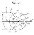
- FIG.2 is a diagram schematically illustrating he connection of the network.
- the radio network 15 is constituted by the radio transmission devices 11, 12, 13 which are terminal communication stations represented by open circles arranged about the radio transmission device 14 which is a control station represented by a black circle.
- the personal computer 1 and the printer output device 2 are connected to the radio transmission device 11 as indicated by a solid line.
- the VRT 3 is connected to the radio transmission device 12 as indicated by a solid line.
- the telephone 5 and the set top box 4 are connected to the radio transmission device 13 as indicated by a solid line.
- the television receiver 6 and the game device 7 are similarly connected to the radio transmission device 14 as indicated by a solid line.
- control station 14 is capable of effecting the communication with all communication stations 11 to 13 on the network 15 through circuits 22 to 24 indicated by dotted lines.
- the communication station 11 is not allowed to effect the communication directly with the remote communication station 13 but is allowed to effect the communication with the control station 14 and with the communication station 12 on the network 15 through the circuits 22 and 21 indicated by dotted lines.
- the communication station 12 is capable of effecting the communication with the control station 14 and the communication stations 11, 13 on the network 15 through the circuits 23, 21 and 25 indicated by dotted lines.
- the communication station 13 is not allowed to effect the communication directly with the remote communication station 11 but is allowed to effect the communication with the control station 14 and with the communication station 12 on the network 15 through the circuits 24 and 25 indicated by dotted lines.
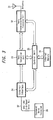
- FIG.3 illustrates the constitution of the radio transmission devices 11 to 14 which are the communication stations.
- the radio transmission devices 11 to 14 are fundamentally constituted in common, and include an antenna 31 for transmission and reception, and a radio transmission/reception processing unit 32 connected to the antenna 31 to execute the radio transmission processing and the radio reception processing, so as to effect radio transmission with other transmission devices.
- the transmission system for effecting the transmission and reception using the radio transmission/reception processing unit 32 of this embodiment will be, for example, the one called OFDM (orthogonal frequency division multiplex) system using multi-carrier signals, and the frequency used for the transmission and reception will be the one in a very high frequency band (e.g., 5 GHz band).
- OFDM orthogonal frequency division multiplex
- the transmission output is relatively weak.
- the output is for effecting the radio transmission over a relatively short distance of from several meters to several tens of meters.
- the data converted by the data conversion unit 33 is fed to an equipment 38 connected through an interface unit 34, and the data fed from the equipment 38 is fed, through the interface unit 34, to the data conversion unit 33 so as to be converted.
- voice, video data or various data are transmitted to, and received from, the equipment 38 through a high-speed serial bus 37 such as IEEE 1394 format which is an external interface of the interface unit 34 of the radio transmission device.
- a high-speed serial bus 37 such as IEEE 1394 format which is an external interface of the interface unit 34 of the radio transmission device.
- the radio transmission device may be incorporated in the body of the equipment 38 that is connected.
- the individual units in each radio transmission device execute the processings being controlled by a control unit 35 constituted by a microcomputer.
- the control unit 35 works to set the individual units to a state represented by the received data.
- an internal memory 36 is connected to the control unit 35 and temporarily stores the data necessary for controlling the communication, number of the communication stations constituting the network, data of a frame period for transmitting a station-synchronizing signal, data of a communication station that transmits the station-synchronizing signal at a predetermined frame period, data for utilizing the transmission path such as the number of band reservations, and a value of the data updating counter.
- a cycle start (CS) signal that will be described later of the network is fed to the radio transmission/reception processing unit 32 through the data conversion unit 33 and is transmitted at a predetermined frame period from the control unit 35.
- the received signal is a cycle start (CS) signal
- the received signal is fed to the control unit 35 through the data conversion unit 33
- the timing of receiving the synchronizing signal is judged by the control unit 35
- a frame period is set based on the synchronizing signal
- the communication control processing is executed at the frame period.
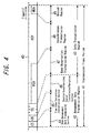
- FIG.4 is a diagram illustrating the constitution of a radio transmission frame according to the embodiment.
- the frame is specified for convenience. However, this structure of the frame needs not necessarily be employed.
- a transmission frame is specified that arrives after every predetermined transmission frame period 41 along the radio transmission line 40, and in which are provided a management data transmission region 42 and a data transmission region 43.
- a down management data transmission section 44 (CS: cycle start) for notifying the frame synchronism and the network common data followed, as required, by the arrangement of a time data correction transmission section 45 (CR: cycle report) and a station-synchronizing signal transmission/reception section 46 (SS: station sync).
- the down management data transmission section (CS) is used for transmitting, from the control station, the data that must be used in common in the network, and includes a fixed length region and a variable length region.
- the number of the communication stations transmitted in the station-synchronizing signal transmission/reception section (SS) is specified and the number of the band reservation transmission regions (RSV) is specified in order to specify the length of the variable length region.
- the communication stations transmitted in the station-synchronizing signal transmission/reception section (SS) is specified and the band reservation transmission region (RSV) is specified.
- the station-synchronizing signal transmission/reception section has a predetermined length and is so constituted that the communication stations that transmit are assigned maintaining a some degree of period by the down management data for the communication stations constituting the network.
- SS station-synchronizing signal transmission/reception sections
- the conditions of connection is informed in the data transmitted by the next local station in the station-synchronizing information transmission/reception section (SS), so that the conditions of connection to the network can be grasped by the communication stations.
- SS station-synchronizing information transmission/reception section
- the data transmission region 43 is constituted by a band reservation transmission region (RSV: reserve) 47 that is set as required, an asynchronous transmission region (ASY: asynchronous) 48 of the centralized management controlled for its transmission by the control station, and a unused region (NUA: not using area) of the noncentralized control which is not controlled for its transmission by the control station.
- RSV band reservation transmission region
- ASY asynchronous transmission region
- NUA unused region
- the data transmission regions can all be transmitted as the asynchronous transmission regions (ASY) of the centralized control.
- the isochronous transmission specified by, for example, IEEE 394 format is executed in the band reservation transmission region (RSV), and the asynchronous transmission is executed in the asynchronous transmission region (ASY).
- RSS band reservation transmission region
- ASY asynchronous transmission region
- FIG.5 is a diagram illustrating the constitution of a cycle start packet.
- the cycle start packet is a data transmitted from the control station in the network to all stations in the network in the down management data transmission section (CS) 44 shown in FIG.4.
- a cycle time data 51-1 indicating the start time of the frame
- a network ID 51-2 for discriminating the network
- a data updating counter 51-3 indicating the timing until the data contained in the cycle start packet (CSP) are updated at one time
- an SSP counter 51-4 indicating the order of data contained in the station sink packet (SSP)
- an SSP period 52-1 indicating the transmission period of the station sink packet (SSP)
- an SSP number 52-2 indicating the number of the station sink packets (SSP) present in the frame
- a band reservation number 52-3 indicating the number of the reserved bands
- a frame end pointer 52-4 indicating a position of ending the frame
- a variable length frame data size 52-5 indicating a given number of data
- a CRC (cyclic redundancy check) 53 for detecting error, as data of fixed lengths.
- variable length data There are further arranged, as variable length data, a station data (#1) 54-1, a station data (#2) 54-2, a station data (#3) 55-1 and a station data (#4) 55-2 of which the lengths vary depending upon the number of the station sync packets (SSP), as well as a band reservation data (#1) 56, a band reservation data (#2) 7 and a CRC 58 for detecting error of which the lengths vary depending upon the number of the preserved bands.
- SSP station sync packets
- FIG. 6 is a diagram illustrating the constitution of a cycle report packet.
- the cycle report packet is a data transmitted to the control station in the network from the communication station that serves as a cycle master on the network in the time data correction transmission section (CR) 45 shown in FIG.4.
- This packet is constituted by a cycle time offset data 61 that represents an offset value of cycle time data of the cycle start packet (CSP) transmitted by the preceding frame from the control station, and a CRC 62 for detecting error.
- CSP cycle start packet
- FIG.7 is a diagram illustrating the constitution of the station sync packet.
- This station sync packet is a data transmitted to the control station and to the surrounding communication stations from the station (communication station) that is specified by the station data of CSP in the station-synchronizing information transmission/reception section (SS) 46 shown in FIG.4.
- This packet is constituted by a sleep mode request 71-1 for notifying the control station of going into sleep, an access control priority order 71-2 for specifying the order of priority of access control right, a station ability 71-3 representing the data processing ability of the station, a station #1 reception quality 72-1, a station #2 reception quality 72-2, a station #3 reception quality 72-3, a station #4 reception quality 72-4, a station #5 reception quality 73-1, a station #6 reception quality 73-2, a station #3 reception quality 73-3 and a station #3 reception quality 73-4 which are the data of connection to other stations, and a CRC 74 for detecting error.
- FIG.8 illustrates the flow of frames by the addition of the band reservation data according to the embodiment.
- the extreme left diagram illustrates the constitution of a cycle start packet (CSP) in a frame 1 in which a band reservation data (#1) 81-3 and a free region 81-4 are arranged with a band reservation number of 2 (81-1) and an updating counter (counted value) of 0 (81-2).
- CSP cycle start packet
- the frame 1 is provided with a free region 81-4 in advance.
- the subsequent frames 2 to 9 show a shift until the band reservation data (#2)
- the frame 2 shows the constitution of a cycle start packet (CSP) in which there are set a band reservation number 3 (82- 1) and an updating counter 8 (82-2), and the band reservation data (#2) 82-4 is added to the free region 81-4.
- CSP cycle start packet
- Illustrated here is a state where the updating counter is set to 8 (42-2) as a timing until a free region 85-4 is arranged.
- the band reservation data (#2) 82-4 is added, and the band reservation can be readily transmitted.
- CSP cycle start packet
- a diagram on the right side of a dotted line illustrates a transition until the free region 85-5 is added in a frame 9 with a band reservation number of 3 (84-1), and illustrates the constitution of a cycle start packet (CSP) in which a band reservation data (#1) 84-3 and a band reservation data (#2) 84-4 are arranged in a state where the updating counter is subtracted to 1 (84-2).
- CSP cycle start packet
- the extreme right diagram illustrates the constitution of a cycle start packet (CSP) in a frame 10 in which a band reservation data (#1) 85-3, a band reservation data (#2) 85-4 and a free region 85-5 are arranged with a band reservation number of 3 (85-1) and an updating counter of 0 (85-2).
- CSP cycle start packet
- the band reservation data can be readily added and the data updating counter is utilized for adding the free region to be ready for adding the band reservation data next time.
- the CSP of this embodiment has a feature in that it usually has the free region at all times for updating (adding) the band reservation data.
- FIG. 9 illustrates the flow of frames by the deletion of band reservation data according to the embodiment.
- the extreme left diagram illustrates the constitution of a cycle start packet (CSP) in a frame 1 in which a band reservation data (#1) 91-3, a band reservation data (#2) 91-4 and a free region 91-5 are arranged with a band reservation number of 3 (91-1) and an updating counter (counted value) of 0 (91-2).
- CSP cycle start packet
- the subsequent frames 2 to 9 show a shift until the band reservation data (#1) 91-3 is deleted.
- the frame 2 shows the constitution of a cycle start packet (CSP) in which the band reservation number 2 (92-1) and the updating counter 8 (92-2) are set, the band reservation data (#1) is deleted, and a free region 92-4 and an unused space 92-5 are arranged in the band reservation data (#2) 92-3.
- CSP cycle start packet
- Illustrated here is a state where the updating counter is set to 8 (92-2) as a timing until the band reservation data (#1) 91-3 is deleted and until the band reservation data ("2) 95-3 and the free region 95-4 are arranged.
- a further right diagram are arranged in a frame 3 with a band reservation number of 2 (93-2), and illustrates the constitution of a cycle start packet (CSP) in which a band reservation data (#2) 93-3, a free region 93-4 and an unused region 93-5 are arranged in a state where the updating counter is subtracted to 7 (93-2).
- CSP cycle start packet
- a diagram on the right side of a dotted line are arranged in a frame 9 with a band reservation number of 2 (94-1), and illustrates the constitution of a cycle start packet (CSP) in which a band reservation data (#2) 94-3, a free region 94-4 and an unused region 95-5 are arranged in a state where the updating counter is subtracted to 1 (94-2).
- CSP cycle start packet
- the extreme right diagram illustrates the constitution of a cycle start packet (CSP) in which a band reservation data (#2) 95-3 and a free region 85-4 are arranged in the frame 10 with a band reservation number of 2 (95-1) and an updating counter of 0 (95-2).
- CSP cycle start packet
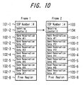
- FIG.10 is a diagram illustrating the flow of frames of when a maximum number of band reservation data are added according to the embodiment.
- a diagram on the left side illustrates a constitution of the frame 1 in which there are arranged a band reservation data (#1) 102-1 ⁇ a band reservation data (#7) 102-7 and a free region 102-8 with a station sync packet (SSP) number of 4 (101-1), an updating counter (counted value) of 0 (101-2) and a band reservation data of 8 (max. value).
- SSP station sync packet
- the diagram on the right side illustrates a constitution of the frame 2 in which there are arranged a band reservation data (#1) 105-1 ⁇ a band reservation data (#8) 105-8 with a station sync packet (SSP) number of 4 (103), an updating counter of 0 (104) and a band reservation data (#8) being added to the free region 102-8.
- SSP station sync packet
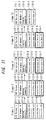
- FIG.11 illustrates the flow of frames of when the station data is deleted according to the embodiment.
- the extreme left diagram illustrates the constitution of a cycle start packet (CSP) of a frame 1 in which there are arranged a station data (#1) 111-4, a station data (#2) 111-5, a station data (#3) 111-6 and a station data (#4) 111-7 with a station sync packet (SSP) period of 1 (111-1), a station sync packet (SSP) number of 4 (111-2) and an updating counter (counted value) of 0 (111-3).
- CSP cycle start packet
- a next right diagram illustrates the constitution of a cycle start packet (CSP) of a frame 2 in which there are arranged a station data (#1) 112-4, a station data (#2) 112-5 as well as a station data (#3) 112-6 and a station data (#4) 112-7 which will be used in the next period with a station sync packet (SSP) period of 1 (112-1), a station sync packet (SSP) number of 2 (112-2) and an updating counter of 8 (112-3).
- CSP cycle start packet
- the updating counter is set to be 8 (112-3) as a timing until the station sync packet (SSP) period and the station sync packet (SSP) number are changed.
- the station data to be transmitted in the next period can be specified.
- a further right diagram illustrates the constitution of a cycle start packet (CSP) of a frame 3 in which there are arranged a station data (#3) 113-4, a station data (#4) 113-5 as well as a station data (#1) 113-6 and a station data (#2) 113-7 which will be used in the next period with a station sync packet (SSP) period of 2 (113-1), a station sync packet (SSP) number of 2 (113-2) and an updating counter being subtracted to 7 (113-3).
- CSP cycle start packet
- a diagram on the right side of a dotted line illustrates the constitution of a cycle start packet (CSP) of a frame 9 in which there are arranged a station data (#3) 114-4, a station data (#4) 114-5 as well as a station data (#1) 114-6 and a station data (#2) 114-7 which will be used in the next period with a station sync packet (SSP) period of 2 (114-1), a station sync packet (SSP) number of 2 (114-2) and an updating counter being subtracted to 1 (114-3).
- CSP cycle start packet
- the extreme right diagram illustrates the constitution of a cycle start packet (CSP) of the frame 10 in which there are arranged a station data (#1) 115-4 and a station data (#2) 115-5 with a station sync packet (SSP) period of 2 (115-1), a station sync packet (SSP) number of 2 (115-2) and an updating counter of 0 (115-3).
- CSP cycle start packet
- FIG.12 is a flowchart illustrating the operation of when the band reservation data is to be changed by the control station.
- step S1 first, it is judged whether a request is issued for changing the band reservation data. When there is no request for changing the band reservation data at step S1, the routine ends.
- a change in the band reservation data is a request for adding or deleting the band reservation number to or from the cycle start (CS) data (down management data). It is assumed that these data are asynchronously transmitted from any communication station.
- CS cycle start
- step S2 When there is a request for changing the band reservation data at step S1, it is judged at step S2 whether it is the addition or the deletion of the band reservation data.
- the band reservation number is added at step S3 from the branch YES, to thereby describe data that is to be added to the free region that has been secured in advance.
- step S4 it is judged whether the addition is possible next time. If the addition is possible, the number of management data to be added is added at step S5 and the routine proceeds to step S8. If the addition is not possible due, for example, to that a maximum number of management data have been set at step S4, then, the routine ends.
- the number of the management data to be deleted is subtracted at step S6 from a branch NO.
- step S7 management data such as other band reservation data are updated, and the routine proceeds to step S8.
- step S8 the data updating counter is set and at step S9, a management data including a band reservation data is built up.
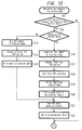
- FIG. 13 is a flowchart illustrating the operation for changing the station data by the control station.
- step S11 first, it is judged whether a request is issued for changing the station data. When there is no request for changing the station data at step S11, the routine ends.
- a change in the station data represents a case where it is requested to add or delete the station data number to or from the cycle start (CS) data (down management data). It is presumed that the control station issues an instruction at any timing.
- CS cycle start
- step S11 When it is requested at step S11 to change the station data, it is judged at step S12 whether it is the addition or deletion of station data from a branch YES.
- the station data number (SSP number) is added at step S13 from a branch NO, the station sync packet (SSP) period is changed (deleted) at step S14, the station data is partly written at step S15, and the routine proceeds to step S21.
- the station sync packet may be set thereby to also specify a position for transmitting the station data.
- the station data number (SSP number) is subtracted at step S16 from the branch YES, the station sync packet (SSP) period is changed (added) at step S17, and a station sync packet (SSP) counter is set at step S18.
- the station data transmitted by the frame period set by the station sync packet (SSP) counter is written into the region of the remaining station data.
- the station data corresponds to the one that is used as the station data of a frame period corresponding to the value of the station sync packet (SSP) after the count-down of the updating counter has been finished.
- step S20 further, the station data transmitted after the next frame period is also written into the region from where the station data is deleted. Therefore, if the management data of the next frame period is not received, it is allowed to estimate the station data of a frame period corresponding to the value of the next station sync packet (SSP) counter. The routine then proceeds to step S21.
- SSP station sync packet
- step S21 the data updating counter is set and at step S22, the management data including the station data is built up.
- FIG.14 is a flowchart of a case of executing the processing for transmitting the management data and for counting down the updating counter by the control station.
- step S31 first, it is judged whether the data updating counter has been set.
- the data updating counter is set at step S31, the data updating counter is subtracted at step S32 from a branch YES, and a management data to be updated is gained at step S33.
- the updated data is transmitted each time.
- step S31 When the data updating counter has not been set at step S31, the existing management data is gained at step S37 from the branch NO, and the routine proceeds to step S36.
- the data including the management data is transmitted as a cycle start packet.
- FIG.15 is a flowchart of the operation for receiving management data by a general communication station.
- step S41 first, it is judged whether the cycle start data (down management data) is received.
- the cycle start data (down management data) is received at step S41, it is judged at step S42 whether the data updating counter is set.
- the data updating counter is set at step S42, a new management data (to be changed) is gained and preserved at step S43.
- step S41 When the cycle start data (down management data) is not received at step S41, the routine readily proceeds to step S44.
- processing is executed at step S46 for updating into a new management data, and the parameters are set to values of after updating.
- the management data to be updated and the update timing are notified to the whole network by securing a region in advance for transmitting the management data to be updated even when the management data has a constitution of a variable length and, hence, the management data can be updated at one timing at a specified timing. That is, the data is updated simultaneously over the whole network by a control operation which is as simple as notifying the data from the control station.
- the control station repetitively transmits the management data to be updated plural times. If the communication stations constituting the network properly receive the management data even once out of plural times of transmission, then, the management data can be updated at one time at a specified timing.
- the timing data transmitted from the control station is used as a predetermined counted value, and the communication station that has received the counted value executes the count-down from the counted value specified by the data, and updates the management data after the value that is counted down has reached a predetermined value.
- the update timing is set by a simple processing by utilizing the counted value.
- the management data is periodically transmitted with a frame period set by the control station as a reference, and the counted value is counted down in a unit of the frame period. Therefore, the update timing is set simultaneously with the management of the frame period, and the update timing is easily brought into agreement over the whole network.
- a free region is secured for updating the management data next time when the value that is counted down has reached a predetermined value, making it possible to update the management data next time at a higher speed.
- the management data over plural periods are transmitted being mixed into a management data until the value that is counted down becomes a predetermined value. Therefore, even when the data are not all received that must be received until the value that is counted down reaches a predetermined value, it is allowed to estimate the subsequent management data.
- the device for controlling transmission of the present invention it is allowed to specify the timing for updating the management data in updating the management data for other transmission devices in the network and to easily update the management data simultaneously in all communication stations in the network.
- a device is realized for updating the variable length data by the control operation of only one time even when there is used a management data of a variable length.
- the timing data obtained by the timing-specifying means is a count-down data that represents a counted value before it is updated, and the update timing is correctly and easily specified by simply transmitting the counted value.
- the device for controlling transmission of the present invention further, plural management data are transmitted in advance by utilizing a region that is to be deleted. Therefore, there is realized a device for transmitting plural management data at one time to all communication stations.
- the timing data obtained by the timing-specifying means is a count-down data that represents a counted value before it is deleted, and the delete timing is correctly and easily specified by simply transmitting the counted value.
- the data can be updated in all communication stations on the network by the update data that has been received in advance at a timing specified by the control device, and the management data can be reliably updated based on the control operation by the control device.
- a free data region is secured for securing the management data free region in order to automatically update the new management data after the elapse of a timing specified by the control device.
Landscapes
- Engineering & Computer Science (AREA)
- Computer Networks & Wireless Communication (AREA)
- Signal Processing (AREA)
- Mobile Radio Communication Systems (AREA)
- Communication Control (AREA)
Abstract
Description
reservation data (#2) 165-4 is added.
transmission/reception sections (SS) except the portion transmitted to the local station, it is allowed to grasp the condition of connection to the communication stations existing around the local station.
constitution of a cycle start packet (CSP) of a
When it has arrived, the management data is updated at step S35.
When the data updating timing has not arrived at step S34, the routine proceeds to step S36.
When the data updating counter is set at step S42, a new management data (to be changed) is gained and preserved at step S43.
Claims (17)
- A method of controlling transmission in a control station on a network comprising said control station and plural communication stations controlled for their communication based upon management data from said control station, wherein:said control station sets in advance management data provided with a free region;when said management data are to be updated, said control station forms timing data for effecting the updating and update management data describing the contents to be updated in said free region , and transmits said update management data to said communication stations; andsaid control station updates the management data on the network at a timing specified by said timing data.
- A method of controlling transmission according to claim 1, wherein said control station repetitively transmits said formed update management data plural times until the timing of updating said management data.
- A method of controlling transmission according to claim 1 or 2, wherein the timing data transmitted from said control station is used as data of a counted value, the counting-down is effected from a counted value specified by said data, and the management data are updated when the value that is counted-down has reached a predetermined value.
- A method of controlling transmission according to claim 3, wherein said management data are periodically transmitted with a frame period set by the control station as a reference, and said counted value is counted down with said frame period as a unit.
- A method of controlling transmission according to any preceding claim, wherein the management data are updated on the network at a timing specified by said timing data, and a free region is set to the management data for the updating next time.
- A method of controlling transmission in a control station on a network comprising said control station and plural communication stations controlled for their communication based upon management data from said control station, wherein:when said management data are to be partly deleted, said control station forms timing data for effecting the deletion and update management data describing other management data utilizing a portion that is to be deleted, and transmits said update management data to said communication stations; andsaid control station deletes part of said update management data on the network at a timing specified by said timing data.
- A method of controlling transmission according to claim 6, wherein said control station repetitively transmits said formed update management data plural times until the timing of deleting part of said management data.
- A method of controlling transmission according to claim 6 or 7, wherein the timing data transmitted from said control station is used as data of a counted value, and the counting-down is effected from a counted value specified by said data, and part of the management data is deleted when the value that is counted-down has reached a predetermined value.
- A method of controlling transmission according to claim 8, wherein said management data are periodically transmitted with a frame period set by the control station as a reference, and said counted value is counted down with said frame period as a unit.
- A device for controlling transmission in a control station on a network comprising said control station and plural communication stations controlled for their communication based upon management data from said control station, said device for controlling transmission comprising:communication means for effecting radio communication with said communication stations on said radio network; andmanagement data-forming means for forming management data having a free region set in said management data used in common on said radio network; whereinwhen said management data are to be updated, said management data-forming means forms timing data for effecting the updating and update management data describing the contents to be updated in said free region , and updates said management data at a timing specified by said timing data.
- A device for controlling transmission according to claim 10, wherein said timing data is used as data of the counted value, and said management data-forming means effects the count down from a counted value specified by the data, and updates the management data when the value that is counted down has reached a predetermined value.
- A device for controlling transmission according to claim 10 or 11, wherein said management data-forming means updates the management data at a timing specified by said timing data, and sets a free region to the management data for updating next time.
- A device for controlling transmission in a control station on a network comprising said control station and plural communication stations controlled for their communication based upon management data from said control station, said device for controlling transmission comprising:communication means for effecting radio communication with said communication stations on said radio network; andmanagement data-forming means for forming management data used in common on said radio network; whereinwhen said management data are to be partly deleted, said management data-forming means forms timing data for effecting the deletion and update management data describing other management data utilizing a portion to be deleted, and deletes part of said management data at a timing specified by said timing data.
- A device for controlling transmission according to claim 13, wherein said timing data is used as data of the counted value, and said management data-forming means effects the count down from a counted value specified by the data, and deletes part of the management data when the value that is counted down has reached a predetermined value.
- A device for controlling transmission according to claim 13 or 14, wherein said management data-forming means deletes part of the management data at a timing specified by said timing data, and sets a free region to the management data for updating next time.
- A communication station controlled for its communication by management data from a control station, said communication station comprising:reception means for receiving management data used in common on a radio network; andcontrol means for controlling the communication according to the management data; whereina free region is set in advance to the management data; andwhen said management data are to be updated, said reception means receives timing data for effecting the updating and update management data describing the contents to be updated in said free region , and updates said management data at a timing specified by said timing data.
- A communication station controlled for its communication by management data from a control station, said communication station comprising:reception means for receiving management data used in common on a radio network; andcontrol means for controlling the communication according to the management data; whereina free region is set in advance to the management data; andwhen said management data are to be partly deleted, said reception means receives timing data for effecting the deletion and update management data describing other management data utilizing a portion to be deleted, and deletes part said management data at a timing specified by said timing data.
Applications Claiming Priority (2)
| Application Number | Priority Date | Filing Date | Title |
|---|---|---|---|
| JP2000155029 | 2000-05-25 | ||
| JP2000155029 | 2000-05-25 |
Publications (2)
| Publication Number | Publication Date |
|---|---|
| EP1158721A2 true EP1158721A2 (en) | 2001-11-28 |
| EP1158721A3 EP1158721A3 (en) | 2003-07-09 |
Family
ID=18660035
Family Applications (1)
| Application Number | Title | Priority Date | Filing Date |
|---|---|---|---|
| EP01304583A Withdrawn EP1158721A3 (en) | 2000-05-25 | 2001-05-24 | Method of controlling transmission and apparatus for controlling transmission |
Country Status (2)
| Country | Link |
|---|---|
| US (1) | US20020009055A1 (en) |
| EP (1) | EP1158721A3 (en) |
Cited By (2)
| Publication number | Priority date | Publication date | Assignee | Title |
|---|---|---|---|---|
| EP2166787A1 (en) * | 2008-09-17 | 2010-03-24 | Fujitsu Limited | Base station, mobile station, and transmission and reception method of broadcast information |
| CN105897513A (en) * | 2016-05-18 | 2016-08-24 | 北京精密机电控制设备研究所 | Data transmission method including time parameters |
Families Citing this family (6)
| Publication number | Priority date | Publication date | Assignee | Title |
|---|---|---|---|---|
| JP3945325B2 (en) * | 2002-07-01 | 2007-07-18 | ソニー株式会社 | Wireless communication system, wireless communication apparatus, wireless communication method, and computer program |
| DE10322950A1 (en) * | 2003-05-22 | 2004-12-16 | Deutsche Thomson-Brandt Gmbh | Setting consistent values for parameter in network with distributed stations, e.g. home network, by sending parameter setting message to network stations after detection of inconsistent values |
| US7440510B2 (en) * | 2003-09-15 | 2008-10-21 | Intel Corporation | Multicarrier transmitter, multicarrier receiver, and methods for communicating multiple spatial signal streams |
| US7423968B2 (en) * | 2004-01-12 | 2008-09-09 | Intel Corporation | Systems and methods to convey additional signaling information in a wireless local area network |
| JP5286944B2 (en) * | 2008-05-30 | 2013-09-11 | 富士通セミコンダクター株式会社 | Receiving apparatus and packet communication method |
| JP5721713B2 (en) * | 2009-07-23 | 2015-05-20 | ノキア コーポレイション | Method and apparatus for reducing power consumption when operating as a Bluetooth Low Energy device |
Family Cites Families (3)
| Publication number | Priority date | Publication date | Assignee | Title |
|---|---|---|---|---|
| SE506548C2 (en) * | 1996-03-25 | 1998-01-12 | Net Insight Ab | Method and apparatus for dynamic signaling in a time multiplexed system |
| US6115390A (en) * | 1997-10-14 | 2000-09-05 | Lucent Technologies, Inc. | Bandwidth reservation and collision resolution method for multiple access communication networks where remote hosts send reservation requests to a base station for randomly chosen minislots |
| JP2000151641A (en) * | 1998-11-13 | 2000-05-30 | Sony Corp | Transmission control method and transmission device |
-
2001
- 2001-05-23 US US09/863,525 patent/US20020009055A1/en not_active Abandoned
- 2001-05-24 EP EP01304583A patent/EP1158721A3/en not_active Withdrawn
Cited By (3)
| Publication number | Priority date | Publication date | Assignee | Title |
|---|---|---|---|---|
| EP2166787A1 (en) * | 2008-09-17 | 2010-03-24 | Fujitsu Limited | Base station, mobile station, and transmission and reception method of broadcast information |
| CN105897513A (en) * | 2016-05-18 | 2016-08-24 | 北京精密机电控制设备研究所 | Data transmission method including time parameters |
| CN105897513B (en) * | 2016-05-18 | 2019-01-15 | 北京精密机电控制设备研究所 | A kind of data transmission method containing time-parameters |
Also Published As
| Publication number | Publication date |
|---|---|
| EP1158721A3 (en) | 2003-07-09 |
| US20020009055A1 (en) | 2002-01-24 |
Similar Documents
| Publication | Publication Date | Title |
|---|---|---|
| US6968156B2 (en) | Wireless transmission method and wireless transmission apparatus | |
| US6980561B1 (en) | System, device, and method for initial ranging in a communication network | |
| US7961632B2 (en) | Communication apparatus and OAM frame transmission method | |
| DE60216647T2 (en) | Method and system for generating a time difference with respect to the minislot clock and counter in headend devices | |
| CN101778405B (en) | Method and system for synchronous acquisition of wireless sensor network for structural health monitoring | |
| KR100615139B1 (en) | Method and apparatus for allocating transmission period in wireless telecommunication system and therefor system | |
| US6091440A (en) | Implementation of delay-critical services in a cable television system | |
| EP1158721A2 (en) | Method of controlling transmission and apparatus for controlling transmission | |
| JP2012055002A (en) | Method for processing data packets received via first interface and device for carrying out the method | |
| EP1206069A1 (en) | Quality of service maintenance of a wireless link in a wireless LAN | |
| Sala et al. | Adaptive control mechanism for cable modem MAC protocols | |
| US7729330B2 (en) | Scheduler and method of scheduling data for communication between a node station and plurality of radio terminals | |
| US6985460B2 (en) | Radio transmission of isochronous and asynchronous information in a network having a variable number of stations | |
| US7164695B2 (en) | Wireless transmission apparatus and wireless transmission method | |
| JP2002171257A (en) | Wireless transmission device and wireless transmission method | |
| JP2002051059A (en) | Transmission control method and transmission control device | |
| US6961353B2 (en) | Radio transmission method and radio transmission apparatus | |
| CN101447803A (en) | Method for estimating signal intensity of EOC system terminal receiver | |
| DE60029307T2 (en) | CABLE MODEM SYSTEM WITH SCAN AND PACKAGE SYNCHRONIZATION | |
| JP2001257706A (en) | Transmission control method and transmission control device | |
| JP2735485B2 (en) | Time-division multiple access method | |
| JP2009296657A (en) | Wireless network management method | |
| Zhong et al. | Cross-layer Dynamic Bandwidth Allocation in G. fin based Centralized Wi-Fi Access Network | |
| CN122002329A (en) | A Weighing Communication Networking Method and System with Multiple Masters, One Slave, and Multiple Monitors | |
| KR100230180B1 (en) | Dynamic Allocation Method of Uplink Slots in Swan 2 Inlet Network |
Legal Events
| Date | Code | Title | Description |
|---|---|---|---|
| PUAI | Public reference made under article 153(3) epc to a published international application that has entered the european phase |
Free format text: ORIGINAL CODE: 0009012 |
|
| AK | Designated contracting states |
Kind code of ref document: A2 Designated state(s): AT BE CH CY DE DK ES FI FR GB GR IE IT LI LU MC NL PT SE TR |
|
| AX | Request for extension of the european patent |
Free format text: AL;LT;LV;MK;RO;SI |
|
| PUAL | Search report despatched |
Free format text: ORIGINAL CODE: 0009013 |
|
| AK | Designated contracting states |
Designated state(s): AT BE CH CY DE DK ES FI FR GB GR IE IT LI LU MC NL PT SE TR |
|
| AX | Request for extension of the european patent |
Extension state: AL LT LV MK RO SI |
|
| RIC1 | Information provided on ipc code assigned before grant |
Ipc: 7H 04L 12/56 B Ipc: 7H 04L 12/28 B Ipc: 7H 04L 12/24 A |
|
| STAA | Information on the status of an ep patent application or granted ep patent |
Free format text: STATUS: THE APPLICATION HAS BEEN WITHDRAWN |
|
| 17P | Request for examination filed |
Effective date: 20031212 |
|
| 18W | Application withdrawn |
Effective date: 20040114 |