EP1158713A2 - Optical waveform for use in a DWDM optical network and systems for generating and processing same - Google Patents
Optical waveform for use in a DWDM optical network and systems for generating and processing same Download PDFInfo
- Publication number
- EP1158713A2 EP1158713A2 EP01302956A EP01302956A EP1158713A2 EP 1158713 A2 EP1158713 A2 EP 1158713A2 EP 01302956 A EP01302956 A EP 01302956A EP 01302956 A EP01302956 A EP 01302956A EP 1158713 A2 EP1158713 A2 EP 1158713A2
- Authority
- EP
- European Patent Office
- Prior art keywords
- signal
- frequency
- overhead
- optical
- wavelength
- Prior art date
- Legal status (The legal status is an assumption and is not a legal conclusion. Google has not performed a legal analysis and makes no representation as to the accuracy of the status listed.)
- Granted
Links
Images


Classifications
-
- H—ELECTRICITY
- H04—ELECTRIC COMMUNICATION TECHNIQUE
- H04B—TRANSMISSION
- H04B10/00—Transmission systems employing electromagnetic waves other than radio-waves, e.g. infrared, visible or ultraviolet light, or employing corpuscular radiation, e.g. quantum communication
- H04B10/07—Arrangements for monitoring or testing transmission systems; Arrangements for fault measurement of transmission systems
- H04B10/075—Arrangements for monitoring or testing transmission systems; Arrangements for fault measurement of transmission systems using an in-service signal
- H04B10/079—Arrangements for monitoring or testing transmission systems; Arrangements for fault measurement of transmission systems using an in-service signal using measurements of the data signal
- H04B10/0795—Performance monitoring; Measurement of transmission parameters
- H04B10/07955—Monitoring or measuring power
-
- H—ELECTRICITY
- H04—ELECTRIC COMMUNICATION TECHNIQUE
- H04B—TRANSMISSION
- H04B10/00—Transmission systems employing electromagnetic waves other than radio-waves, e.g. infrared, visible or ultraviolet light, or employing corpuscular radiation, e.g. quantum communication
- H04B10/07—Arrangements for monitoring or testing transmission systems; Arrangements for fault measurement of transmission systems
- H04B10/075—Arrangements for monitoring or testing transmission systems; Arrangements for fault measurement of transmission systems using an in-service signal
- H04B10/077—Arrangements for monitoring or testing transmission systems; Arrangements for fault measurement of transmission systems using an in-service signal using a supervisory or additional signal
-
- H—ELECTRICITY
- H04—ELECTRIC COMMUNICATION TECHNIQUE
- H04L—TRANSMISSION OF DIGITAL INFORMATION, e.g. TELEGRAPHIC COMMUNICATION
- H04L27/00—Modulated-carrier systems
- H04L27/10—Frequency-modulated carrier systems, i.e. using frequency-shift keying
-
- H—ELECTRICITY
- H04—ELECTRIC COMMUNICATION TECHNIQUE
- H04L—TRANSMISSION OF DIGITAL INFORMATION, e.g. TELEGRAPHIC COMMUNICATION
- H04L5/00—Arrangements affording multiple use of the transmission path
- H04L5/02—Channels characterised by the type of signal
-
- H—ELECTRICITY
- H04—ELECTRIC COMMUNICATION TECHNIQUE
- H04J—MULTIPLEX COMMUNICATION
- H04J14/00—Optical multiplex systems
- H04J14/02—Wavelength-division multiplex systems
- H04J14/0298—Wavelength-division multiplex systems with sub-carrier multiplexing [SCM]
Definitions
- the present invention relates generally to dense wavelength division multiplexed (DWDM) optical networks and, in particular, to optical waveforms used in such networks and to systems used for generating and decoding such waveforms.
- DWDM dense wavelength division multiplexed
- an aggregate optical signal travelling on a single optical fiber occupies multiple wavelengths, each of which carries a respective high-speed optical data signal. Although they may travel together along multiple spans throughout the network, the individual optical data signals carry information that is independent and is associated with its own source and destination network elements.
- DWDM dense wavelength division multiplexed
- a downstream network element in a DWDM network It is often desirable for a downstream network element in a DWDM network to have knowledge of the average intensity of the optical data signal occupying each wavelength. This is to allow the network element to initiate control functions such as amplifier gain adjustment and protection switching in a timely fashion. In order to keep costs to a minimum, it is desirable for the downstream network element to have access to the intensity information at multiple wavelengths without having to resort to wavelength demultiplexing and conversion of multiple (possibly hundreds of) optical signals into electrical form.
- a transmitter first modulates the optical data signal on each wavelength with a respective dither signal of a certain amplitude.
- the dither signals are described as being pseudo-random noise (PN) sequences which are distinct for each wavelength.
- PN pseudo-random noise
- the transmitter measures the modulation depth of each individual resultant signal after modulation with the corresponding dither signal and adjusts the amplitude of the dither signal until a known "modulation depth" is achieved.
- the “modulation depth” is commonly defined as the root-mean-square (RMS) value of the dither signal divided by the average intensity of the optical data signal being modulated.
- a receiver located at a downstream network element can estimate the average intensity of the optical data signal at multiple wavelengths of an incoming optically multiplexed signal by: (a) tapping a portion of the multiplexed signal using an inexpensive optical coupler; (b) converting the tapped optical signal to electrical form; (c) low-pass filtering the electrical signal to provide an aggregate dither signal; (d) separating the dither signals by matching them with known PN sequences; (e) measuring the RMS value of each dither signal; and (f) dividing the RMS value of each dither signal by the known modulation depth.
- the RMS value of each dither signal present in the aggregate dither signal must be determined to a high degree of accuracy. Of course, this can only occur if the receiver accurately detects the presence of each dither signal in the aggregate dither signal. If the individual dither signals are PN sequences (as per U.S. Patent 5,513,029), then in order to achieve the requisite degree of accuracy, the receiver must sample the aggregate dither signal at the center of the "chip period" of each PN sequence.
- the dither signals are generated on an independent basis, possibly by sources located at different parts of the network, there will generally be phase offsets among the dither signals contained in the aggregate dither signal. Therefore, in order to compensate for such differences in phase, the sampling rate used at the receiver must be much higher than the chip rate. It is therefore apparent that there exists a trade-off between sampling precision (leading to accurate RMS estimates and hence accurate estimates of average intensity) and computational simplicity.
- the problem is no less severe if the dither signals used for different optical wavelengths occupy different frequencies rather than different PN sequences.
- the step of distinguishing the various dither signals would involve passing the aggregate dither signal through a parallel array of filters, one for each wavelength. As the number of wavelengths (and filters) increases, the bandwidth of each filter will have to be decreased in order to allow only the desired dither signal to pass through to the RMS detection stage, with the effect of deleteriously increasing the filter design complexity.
- the invention is directed to providing a method and system for estimating the average intensity of an optical signal at each of one or more wavelengths with sufficiently high accuracy and sufficiently low computational complexity.
- the optical data signal on each wavelength is modulated with a respective overhead (dither) signal, resulting in a respective dithered optical signal.
- the amplitude of a particular overhead signal used to modulate the corresponding optical data signal is chosen so that the RMS value of the overhead signal in the dithered optical signal is proportional to the average intensity of the optical data signal.
- the instantaneous frequency of each overhead signal is time-varying and each possible frequency belongs to a distinct set of frequencies which are all harmonically related to a fundamental frequency.
- each overhead signal is uniquely isolated from an aggregate overhead signal. In this way, one avoids having to perform optical demultiplexing of the individual dithered optical signals at a receiver in order to extract the individual overhead signals. Furthermore, the harmonic relationship among the frequencies allows improved accuracy of RMS detection at a receiver as well as reduced computational complexity, as each possible frequency for each overhead signal can be made to fall at the center of one of the frequency bins of a single FFT of reasonable size performed at a receiver.
- the overhead signal has an RMS value that is a function of an average intensity of the respective optical data signal and further having an instantaneous frequency content that is time-varying.
- the invention further provides that the instantaneous frequency content of each overhead signal is uniquely associated with the respective wavelength and also that the instantaneous frequency content of each overhead signal is harmonically related to a common fundamental frequency.
- the number of wavelengths is usually at least two and is much larger in a dense system.
- the RMS value of each overhead signal may be proportional to the average intensity of the respective optical data signal. Variations of the frequency content of at least one overhead signal may encode control information.
- the combined frequency content of each overhead signal may span a frequency range between 300 kilohertz and 1 megahertz.
- a method and system for generating a dithered optical signal including the steps of intensity modulating an optical carrier modulated data signal in accordance with an overhead signal to produce the dithered optical signal, measuring a modulation depth of the dithered optical signal and adjusting the amplitude of the overhead signal as a function of the measured modulation depth.
- the overhead signal has an instantaneous frequency content which is time-varying and is uniquely associated with the optical wavelength of the carrier, wherein the instantaneous frequency content is selected from a set of frequencies which are harmonically related to a common fundamental frequency.
- first and second dithered optical signals each of which is generated according to the above described method.
- the frequency content of the first and second overhead signals be harmonically related to a common fundamental frequency.
- the first dithered optical signal may be optically coupled to the second dithered optical signal.
- a method and system for determining the average intensity of at least one optical data signal generated in a received optical signal having been according to any method which ensures that each optical data signal occupies a respective wavelength of interest and has an intensity that is amplitude modulated by a respective overhead signal having an instantaneous frequency content that varies with time.
- the method includes the steps of transforming the received optical signal into an aggregate signal in electrical form, transforming the aggregate signal into a frequency domain vector and, for each wavelength of interest:
- the step of transforming the aggregate signal into a frequency-domain vector may include sampling the aggregate electrical signal and executing a fast Fourier transform (FFT) on a finite number of samples, to produce the frequency-domain vector.
- FFT fast Fourier transform
- the method may include the intermediate steps of acquiring the samples over an integer number of blocks each having a length substantially equal to the inverse of the fundamental frequency, summing each block of windowed samples on an element-by-element basis to produce a block of summed elements and dividing each summed element by the integer number.
- Fig. 1 shows a plurality of dithered optical signals 10, 20, 30 that are carried on respective distinct wavelengths by a common optical transmission medium (e.g., an optical fiber or silica waveguide).
- a common optical transmission medium e.g., an optical fiber or silica waveguide.
- Each of the dithered optical signals 10, 20, 30 consists of light which has been twice modulated, once by a stream of data pulses and another time by an overhead signal.
- each of the dithered optical signals 10, 20, 30 is made up of a respective one of a plurality of high-speed (e.g., 10 Gbps) optical data signals 12, 22, 32, each of which is typically binary pulse modulated light that represents a logic zero when it has a low intensity and a logic one when it has a high intensity.
- the desired intensity of the light at the low intensity is typically the same for all the optical data signals 12, 22, 32 while the desired intensity of the light at the high intensity will be different, depending on the optical power with which the respective optical data signal is transmitted.
- Each of the optical data signals 12, 22, 32 is further amplitude modulated at its source by a respective one of a plurality of low-frequency overhead signals 14, 24, 34.
- the amplitude of each overhead signal is chosen such that the modulation depth (i.e., the ratio of the RMS value of the overhead signal to the average intensity of the corresponding optical data signal) is equal to a known value. This allows an eventual downstream network element to obtain, inferentially, the value of the average intensity of each optical data signal simply by measuring the RMS value of the corresponding overhead signal and multiplying it by the known modulation depth.
- each of the overhead signals 14, 24, 34 offers frequency diversity in order to provide immunity against, for instance, framing of the optical data signals at 8 kHz.
- the control channel employs frequency shift keying (FSK) having a relatively small number of frequency possibilities, which also keeps the receiver complexity at a relatively low level.
- FSK frequency shift keying
- each overhead signal can thus be changed on a regular basis to provide frequency diversity.
- the frequency of each overhead signal can be changed in accordance with control information, thereby causing the overhead signal to serve as a low bit rate "control channel".
- the control information could include connectivity information, such as the address of the source transmitter and/or the bit rate (e.g., OC-48, OC-192) and/or format (e.g., SONET, SDH) of the corresponding optical data signal.
- connectivity information such as the address of the source transmitter and/or the bit rate (e.g., OC-48, OC-192) and/or format (e.g., SONET, SDH) of the corresponding optical data signal.
- bit rate of each control channel the number of frequency possibilities for each overhead signal and possible values for the frequencies themselves have not been discussed.
- One example of a suitable bit rate for the control channel at a given wavelength is 2 bits per second and one example of a suitable number of frequency possibilities is 8. Given these two parameters, the minimal interval between changes to the frequency content of the overhead signal will be 1.5 seconds. Of course, other bit rates and other numbers of frequency possibilities are possible.
- each overhead signal is only allowed to occupy frequencies from an assigned set.
- the present invention requires that all the frequencies used for all the overhead signals be harmonically related to a common fundamental frequency (denoted f 0 ), although f 0 need not itself be a member of the set of frequencies associated with any particular wavelength.
- f 0 is discussed in more detail at various points in the sequel and is basically influenced by the number of wavelengths sharing the same fiber, by the number of frequencies in each set of assigned frequencies, by what is considered to be a convenient FFT size (e.g., a power of 2), and by the range of possible sampling rates at the receiver.
- FFT size e.g., a power of 2
- a suitable frequency plan for 256 wavelength channels is shown in Fig. 2, where there are taken to be 256 different frequency sets 1001, 1002, ..., 1256, each containing 8 individual frequencies A, B, C, D, E, F, G, H.
- the frequencies in each set could be evenly spaced as shown, although they are only actually required to be spaced by integer multiples of f 0 .
- the sets of frequencies 1001, 1002, ..., 1256 can be contiguous and each adjacent pair of frequency sets is separated by a guard band 50.
- the guard bands 50 should each have a width that is a multiple of the fundamental frequency f 0 .
- the width of all guard bands 50 has been chosen to be equal to twice the fundamental frequency f 0 .
- the lowest frequencies of any two adjacent channels are separated by nine times the fundamental frequency f 0 .
- guard bands are not required, in which case the sets of frequencies need not be contiguous (e.g., they may be interleaved).
- the fundamental frequency f 0 has been chosen as 32.2265625 Hz, the first set of frequencies begins at 318.75 kHz, and the last set of frequencies ends at 392.94 kHz. In this particular example, therefore, the total frequency span is equal to 74.19 kHz.
- the lowest frequency (A) in the lowest set of frequencies (1001) should be sufficiently high to avoid small signal losses due cascaded erbium-doped fiber amplifiers (EDFAs), while the highest frequency (H) in the highest set of frequencies (1256) should be sufficiently low to avoid complexity issues at the receiver side.
- a suitable total frequency span will desirably occupy a subset of the 300 kHz to 1 MHz range, although other ranges are possible.
- the fundamental frequency f 0 should be low enough such that the corresponding total frequency span is in a desirable range, e.g., 300 kHz to 1 MHz.
- the actual choice of f 0 within these boundaries will affect the sampling rate (denoted f R ) which must be used at a receiver and will therefore depend on receiver requirements as described in further detail later on.
- the dithered optical signal O D occupies a wavelength of interest, while the main optical signal on the input optical fiber 302 consists of optical signal content on zero or more wavelengths with no optical signal content on the wavelength of interest.
- the dithered optical signal O D on the tributary optical fiber 306 is generated by a system comprising a variable optical modulator (VOM) 310, an optical data signal generator 312 and a control module 314.
- VOM variable optical modulator
- the dithered optical signal O D is generated by the variable optical modulator 310, which modulates an optical data signal (denoted O T ) received from the optical data signal generator 312 as a function of an electrical overhead signal (denoted E OH ) received from the control module 314.
- the system of Fig. 3 could be located at a network element such as a switch or add/drop mux/demux (ADM).
- the optical data signal generator 312 generically represents a source of optical data, which may originate locally or which may have arrived along an arbitrary direction from another network element.
- the electrical overhead signal E OH produced by the control module 314 causes the dithered optical signal O D produced by the VOM 310 to have the characteristics previously described with reference to Figs. 1 and 2. That is to say, the resulting dithered optical signal O D has a modulation depth that is related to the average intensity of the optical data signal O T , while the overhead signal E OH itself has frequency variations that provide frequency diversity.
- One way of providing frequency diversity is to encode connectivity information into the frequency variations of the overhead signal E OH .
- the possible frequencies of the overhead signal E OH are uniquely associated with the wavelength of the optical data signal O T so that knowledge of the wavelength of the dithered optical signal carrying a particular overhead signal will not be required when detecting and decoding that overhead signal at a receiver located further downstream.
- control module 314 desirably utilizes an FSK signal generator 210 or some similarly suitable generation means for generating an electrical control signal (denoted E C ) which exhibits frequency variations. These frequency variations may encode connectivity information. In either case, the frequency of the control signal E C at any given instant belongs to a set of frequencies that is uniquely associated with the wavelength of the optical data signal O T .
- the FSK signal generator 210 is connected to a controllable gain amplifier 220, which generates the overhead signal E OH by amplifying the control signal E C in accordance with an electrical gain control signal (denoted E G ) received from a dither processing module 230.
- the value of the gain control signal E G is controlled by the dither processing module 230 so that the resulting overhead signal E OH produced by the amplifier 220 is at the appropriate amplitude, resulting in a known (or “reference") modulation depth (denoted M D ) of the dithered optical signal O D at the output of the VOM 310.
- the dither processing module 230 is made up of a feedback path 240, a detection unit 250 and a comparison unit 260.
- the feedback path 240 is connected between the output of the VOM 310 and an input of the detection unit 250.
- the feedback path 240 comprises an optical tap coupler 242, a photodiode 244 and a trans-impedance amplifier 246.
- the optical tap coupler 242 taps a portion of the optical power of the dithered optical signal O D .
- the photodiode 244 converts the tapped optical signal to a photocurrent which is then converted to a voltage by the trans-impedance amplifier 246.
- the trans-impedance amplifier 246 thus supplies an input of the detection unit 250 with a feedback signal (denoted E F ), which is an electrical version of the dithered optical signal O D .
- the feedback signal E F has an overhead portion which closely matches the low rate FSK overhead signal E OH .
- the remainder of the feedback signal E F does not necessarily accurately represent the variations in the optical data signal O T because the coupler 242, photodiode 244 and/or the trans-impedance amplifier 246 may be bandwidth-limited components. Nevertheless, it is usually the case that the feedback signal E F does have a DC voltage which is representative of the average intensity of the optical data signal O T .
- the detection unit 250 comprises circuitry, control logic or software for (a) determining the RMS value of the overhead portion of the feedback signal E F ; (b) determining the DC voltage of the feedback signal E F ; and (c) computing the quotient of the two results in order to obtain a modulation depth estimate (denoted M D ').
- the detection unit 250 performs a correlation between the feedback signal E F and all possible frequencies of the electrical control signal E C .
- the detection unit 250 may comprise an analog-to-digital converter (ADC), a plurality of time-domain correlators, a peak detector and various digital or analog low-pass filters.
- ADC analog-to-digital converter
- the complexity requirements of the detection unit 250 are relatively low because the feedback signal E F contains a single overhead signal having a limited number of frequency possibilities.
- Improved correlation accuracy and further reduced complexity can be realized through synchronous correlation of the feedback signal E F with the control signal E C .
- This can be achieved by providing a delayed replica of the control signal E C from the output of the FSK signal generator 210 via a delay element 255. If used, the delay element 255 should introduce a delay that is approximately equal to the delay through the amplifier 220, the VOM 310, the splitter 242, the photodiode 244 and the trans-impedance amplifier 246.
- the detection unit 250 may comprise a simple capacitor or resistive-capacitive network. In order to determine the quotient of the two RMS value of the dither signal and the DC voltage of the feedback signal, thereby obtaining the modulation depth estimate M D' , the detection unit 250 may comprise a digital division module or other suitable circuitry, software and/or control logic.
- the output of the detection unit 250 is thus the modulation depth estimate M D ' which is fed to the comparison unit 260.
- the comparison unit 260 comprises circuitry, control logic or software for comparing the received modulation depth estimate M D' to the reference modulation depth M D .
- the output of the comparison unit 260 is scaled and used to modify the electrical gain control signal E G which is fed to the amplifier 220.
- control signal E C is generated by the FSK signal generator 210 and, by virtue of its frequency variations and content, the control signal E C may encode connectivity information.
- the control signal E C is amplified by the amplifier 220 and emerges as the overhead signal E OH .
- the overhead signal E OH then modulates the intensity of the optical data signal O T , resulting in the dithered optical signal O D .
- the dithered optical signal O D is tapped by the coupler 242 and subsequently converted into the feedback signal E F by the photodiode 244 and the trans-impedance amplifier 246.
- the detector unit 250 correlates the feedback signal E F with a (delayed) version of the control signal E C in order to determine the RMS value of the overhead portion of the feedback signal E F .
- the DC voltage of the feedback signal E F is obtained at a capacitor output and remains unaffected by variations due to the overhead portion of the feedback signal E F .
- the detector unit 250 divides the RMS value of the overhead portion of the feedback signal E F by the average DC voltage of the feedback signal E F to obtain the modulation depth estimate M D' .
- the comparison unit 260 then adjusts the gain control signal E G as a function of the difference between the modulation depth estimate M D' and the reference modulation depth M D . (The modulation depth estimate M D' may be different from the reference modulation depth M D due to temperature fluctuations, for example.)
- the dithered optical signal O D occupying the wavelength of interest shares the output optical fiber 308 with other optical signals on other wavelengths. It is envisaged that these other signals may also be dithered optical signals which have been modulated by respective overhead signals that are also FSK signals. If this is indeed the case, then the FSK signals associated with different wavelengths should have the characteristics described earlier with reference to Figs. 1 and 2.
- a multi-wavelength optical signal While traveling through a portion of the network, a multi-wavelength optical signal suffers wavelength-dependent losses introduced by the optical medium itself and by various intervening cascades of erbium-doped fiber amplifiers. These losses affect the intensity of each dithered optical signal to a degree which may depend on the wavelength.
- the corresponding overhead signal and the corresponding optical data signal are affected in the same way. Therefore, the ratio of the RMS value of the overhead signal to the average intensity of the optical data signal remains constant. In other words, the modulation depth of each dithered optical data signal remains unchanged, despite attenuation of the dithered optical signal.
- an intermediate network element can infer the average intensity of the corresponding optical data signal. It may also be of interest for the intermediate network element to decode connectivity information associated with one or more optical wavelengths. It would be highly desirable to perform these tasks without having to provide optical demultiplexing circuitry at the intermediate network element. Furthermore, it would be desirable to perform these tasks with reasonably low computational complexity.
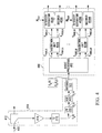
- Fig. 4 shows a system for estimating the average intensity of one or more optical data signals occupying respective wavelengths of an incoming multi-wavelength optical signal arriving on an optical fiber 400.
- the system may also be used for decoding connectivity information associated with each of these wavelengths.
- each individual wavelength in the incoming multi-wavelength optical signal is occupied by a dithered optical signal that has been modulated with an FSK overhead signal using a system such as that shown in Fig. 3.
- the modulation scheme used for multiple wavelengths is orthogonal as previously described with reference to Figs. 1 and 2, where the instantaneous frequency of each overhead signal belongs to a distinct set of frequencies and is harmonically related to a common fundamental frequency f 0 .
- the system in Fig. 4 comprises a data acquisition section 410 connected to a processing section 450.
- the data acquisition section 410 comprises an optical splitter 412 which intercepts the optical fiber 400 that carries the incoming multi-wavelength optical signal.
- the splitter 412 is connected in series to other components in the data acquisition section 410, including a photodiode 414, a trans-impedance amplifier 416, a low-pass filter 418, an analog-to-digital converter 420 and an averaging unit 422.
- the photodiode 414 and the trans-impedance amplifier 416 can be of standard design; these components provide the low-pass filter 418 with an electrical signal (denoted E A (t)) that is representative of the aggregate light present on the optical fiber.
- the low-pass filter 418 ensures that the electrical signal (denoted E L (t)) at its output contains just the aggregate of the low-frequency overhead signals present on the multiple wavelengths.
- the low-pass filter 418 can accordingly be band limited to below 1 MHz.
- the low-pass filter 418 could also be a band-pass filter with a pass band in the range of 300 kHz to 1 MHz.
- the filter used should have at least as wide a bandwidth as the aggregate overhead signal while filtering out variations due to high speed data.
- the analog-to-digital converter (ADC) 420 can also be of standard design and comprises circuitry for sampling the signal E L (t) received from the low-pass filter 418 at a sampling rate (denoted f R ) to produce a sample stream (denoted S L (n)) at its output. Because E L (t) is a band limited signal, the sampling rate f R can actually be below the so-called Nyquist rate. This technique is known as "bandpass sampling” and requires that:
- f R should be chosen such that:
- Requirement (c) facilitates execution of a subsequent fast Fourier transform (FFT) in the processing section 450, while requirement (d) ensures that the frequency points of this ensuing FFT will fall exactly at the frequencies chosen for the overhead signals.
- FFT fast Fourier transform
- requirements (c) and (d) further restrict the sampling rate to either 528,000 samples per second (for an FFT size of 16,384) or 264,000 samples per second (for an FFT size of 8192).
- this component comprises circuitry, software or control logic for buffering the sample stream S L (n) exiting the ADC 420 for the duration of an acquisition interval of T acq seconds.
- the number of samples buffered during this acquisition interval of length T acq seconds is denoted Z TOTAL and is equal to Z 0 x Y, where:
- the averaging unit 422 also comprises circuitry, software and/or control logic for performing a windowing operation on the set of Z TOTAL samples buffered during T acq seconds.
- the averaging unit 422 also comprises suitable circuitry, software and/or control logic for separating the windowed set of Z TOTAL samples into Y blocks of Z 0 samples and for averaging the blocks on an element-by-element basis. This produces an output block of Z 0 windowed and averaged samples, conveniently denoted in matrix form by [S A (1) ... S A (Z 0 )].
- the output of the averaging unit 422 is a block of averaged samples [S A (1) ... S A (Z 0 )], one such block being produced every T acq seconds.
- the elements of this block of averaged samples [S A (1) ... S A (Z 0 )] are samples corresponding to a windowed, periodically averaged version of the aggregate overhead signal formed from the individual overhead signals associated with the various wavelengths in the incoming multi-wavelength optical signal arriving on the optical fiber 400.
- Z 0 will be a power of two by virtue of having chosen the sampling rate f R to result in the production of 2 N samples in T 0 seconds for some integer N.
- the averaging unit 422 feeds the block of averaged samples [S A (1) ... S A (Z 0 )] to a basic processing unit 452 located at the front of the processing section 450.
- the processing section 450 also comprises a plurality (M) of validation units 454 A -454 M connected to the basic processing unit 452. Connected to each validation unit is a respective one of a plurality of intensity estimators 456 A -456 M and a respective one of a plurality of decoders 458 A -458 M .
- M could equal 256 in a specific embodiment consistent with the 256 frequency sets 1001-1256 represented in Fig. 2.
- the basic processing unit 452 comprises circuitry, software and/or control logic for extracting and determining the frequency content of each individual overhead signal contained in the block of averaged samples [S A (1) ... S A (Z 0 )].
- RMS value and the instantaneous frequency of each overhead signal are derived from the block of averaged samples [S A (1) ... S A (Z 0 )].
- each overhead signal consists of a tone whose instantaneous frequency of the tone belongs to a restricted set of frequencies and changes with time to provide frequency diversity and, possibly, to convey control information.
- each overhead signal (tone) has an associated RMS value that is intended to be used by the receiver in Fig. 4 for estimating the average optical intensity of the corresponding optical data signal.
- the basic processing unit 452 produces, for each overhead signal associated with a respective optical wavelength, a respective one of a plurality of "candidate” RMS values (denoted C RMS,A ,...,C RMS,M ) and a respective one of a plurality of "candidate” frequencies (denoted C FREQ,A ,...,C FREQ,M ). For each overhead signal, these two respective outputs are fed along one or more control links to the respective one of the validation units 454 A -454 M .
- Each validation units 454 i , i ⁇ ⁇ A, B, ..., M ⁇ comprises circuitry, software or control logic for processing the candidate RMS value C RMS,i and the candidate frequency C FREQ,i associated with the respective overhead signal in order to determine whether a transition has occurred in the last T acq seconds. If so, the validation unit in question labels the corresponding candidate frequency and its associated RMS value as being invalid.
- the operation performed by each of the validation units 454 A -454 M may consist of determining whether the candidate RMS value associated with the respective overhead signal is above a certain pre-determined threshold. If not, it is concluded that a transition is under way and that the candidate RMS value and the corresponding candidate frequency are invalid.
- T acq is much smaller than the time during which the frequency content of an overhead signal remains constant (e.g., on the order of 1.5 seconds)
- an invalid version of the candidate frequency and candidate RMS value will usually be followed by one or more valid versions of the candidate frequency and candidate RMS value.
- the validation unit in question say, 454 p
- the validation unit in question will send a "valid RMS value” (denoted V RMS,p ) to its intensity estimator 456 p along one control line and a "valid frequency” (denoted V FREQ,p ) to the decoder 458 p along another control line.
- Each of the intensity estimators 456 A -456 M comprises circuitry, software or control logic for dividing the valid RMS value of each overhead signal by the respective reference modulation depth M D,A -M D,M associated with that optical wavelength, thus arriving at an estimate of the average intensity of the optical data signal carried on the corresponding optical wavelength.
- the optical intensity determined in this manner can subsequently be processed by a controller (not shown), which may take action such as to increase the gain or initiate protection switching if the computed intensity is found to be less than a pre-determined nominal value.
- each such component comprises circuitry, software and/or control logic for extracting the control information, if any, encoded by the instantaneous frequency as well as the frequency variations of the respective overhead signal.
- Such information can include connectivity information and could be provided to a controller at the receiver, which may take switching action based upon the decoded connectivity information.
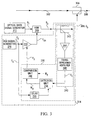
- FIG. 5 a functional block diagram illustrating the operational steps executed by the basic processing unit 452 when processing a block of Z 0 averaged samples [S A (1) ... S A (Z 0 )] received from the averaging unit 422 at intervals of T acq seconds.
- the functional elements shown in Fig. 5 could be implemented in hardware, software, firmware or any combination thereof.
- the basic processing unit 452 shown in Fig. 5 implements matched filter detection in the frequency domain which gives superior performance in terms of noise removal.
- the first step is the provision of a fast Fourier transform (FFT) functional element 510 at the input to the basic processing unit 452.
- the FFT functional element 510 performs an FFT of suitable size on the block of Z 0 averaged samples [S A (1) ... S A (Z 0 )], received once every T acq seconds.
- the result of the FFT yields a spectrum vector denoted [X A (1) ... X A (Z 0 )], which shows the spectral content at each of Z 0 evenly spaced frequencies.
- the execution of a fast Fourier transform is simplified by virtue of having made Z 0 a power of two through proper selection of the sampling rate f R and the fundamental frequency f 0 .
- each of a. plurality of correlators 520 i,j , i ⁇ ⁇ A, B, ... , M ⁇ , j ⁇ ⁇ A, B, ... , N ⁇ performs a frequency domain cross-correlation between the spectrum vector [X A (1) ... X A (Z 0 )] and a respective one of a plurality of spectral templates 525 i,j , i ⁇ ⁇ A, B, ... , M ⁇ , j ⁇ ⁇ A, B, ... , N ⁇ .
- M is still the number of overhead signals (i.e., the number of frequency sets in the spectrum), while N is the number of frequencies per set. It should be appreciated that N may be different for each overhead signal but is in this case assumed to be constant in the interest of clarity. In the specific example described in Fig. 2, M would equal 256 and N would equal 8.
- Each of the spectral templates 525 i,j can be a sparse vector having a "one" at a single frequency point of interest and a "zero" elsewhere.
- Each correlator 520 i,j may therefore perform an element-by-element multiplication of the spectrum vector [X A (1) ... X A (Z 0 )] with the corresponding spectral template 525 i,j , to yield a sparse vector having zeroes at all frequencies except for the frequency of the corresponding spectral template, where the value of the sparse vector at that frequency is the value of the spectrum vector [X A (1) ... X A (Z 0 )] at that frequency.
- a plurality of inverse FFT (IFFT) functional elements 530 i,j performs short IFFTs on the output of the respective correlator 520 i,j .
- the length of each IFFT so performed is desirably much shorter than the length of the FFT performed by the FFT functional element 510.
- each IFFT functional element 530 i,j is a sparse vector with at most one non-zero element
- the output of each IFFT functional element 530 consists of either zeroes or samples of a time domain sinusoid (tone) at the template frequency.
- the result of the IFFT performed by each of the IFFT functional elements 530 i,j is thus passed through a respective one of a plurality of peak detectors 540 i,j in order to determine the amplitude of the resulting time-domain signal. It should be appreciated that during a change in the instantaneous frequency of an overhead signal, two or more peak detectors associated with that overhead signal may produce sinusoids of comparable amplitude.
- each of the peak detectors 540 i,j for a common optical wavelength i.e., for a common value of i
- Each of the maximum selectors 550 A -550 M is operable to identify the frequency of the tone which has the highest amplitude and to compute the RMS value of that tone. Since the relationship between RMS and peak values for a sinusoid is well known, each of the maximum detectors 550 A -550 M may simply convert the output of the one peak detector generating the highest peak value to an RMS value.
- the frequency at which the maximum selector associated with the overhead signal on a particular optical wavelength (say, maximum selector 550 p ) has identified the maximum amplitude is output to the corresponding validation unit 454 p as the previously described candidate frequency C FREQ,p for that overhead signal while the actual peak value (converted to an RMS value) is provided to validation unit 454 p as the previously described candidate RMS value C RMS,p .
- Each of the validation units 454 A -454 M then proceeds as previously described.
- implementation options include using a different size of FFT, using a different size of IFFT, using different methods of cross-correlation, each of which may be associated with its own trade-off in terms of performance accuracy versus computational complexity.
- Other options include simplifying the maximum detection process by providing a simple software algorithm to run through the results of the FFT functional element 510 and isolate, for each of the M sets of frequencies, the frequency point (and the corresponding FFT value) having the largest FFT value from among the frequency points in the set.
- a high degree of accuracy in RMS estimation can be attained by performing a single FFT of manageable size (e.g., of length 16,384 or 8,192) every T acq seconds.
- the complexity of the system is further kept in check since the IFFTs performed by the IFFT functional elements 530 i,j are much shorter than the FFT performed by the FFT functional element 510 i,j .
- the invention also provides improved performance as a result of the specially selected frequency range of the overhead signals, which contains frequencies sufficiently high to be immune to the small-signal response of cascaded EDFA amplifiers and sufficiently low to allow low complexity at the intermediate network element where detection is required.
- the overhead signals are FSK signals with frequency content that is dynamic renders the overhead signals immune to periodic interference which may arise from the transmission of frame-based optical data signals.
- each overhead signal has been described as occupying only one frequency at a time, but it is possible (although less energy efficient) to attain frequency diversity and convey control information by allowing an overhead signal to occupy more than one frequency at any given instant.
- the overhead signal will then occupy one (or possibly more) of these frequencies at a time and the actual instantaneous frequency will vary with time in order to provide frequency diversity.
- the time variations could be used as a control channel to transmit control information.
- frequency diversity allows the system to combat interference such as periodic interference due to framing of the underlying optical data signal.
- the fact that the frequencies in the set are harmonically related allow the receiver system to achieve good RMS measurement accuracy at a relatively low computational complexity through a suitable choice of a sampling rate and FFT size, because each possible frequency in the overhead signal can be made to fall at the center of a frequency bin of the resulting FFT.
Landscapes
- Engineering & Computer Science (AREA)
- Signal Processing (AREA)
- Computer Networks & Wireless Communication (AREA)
- Physics & Mathematics (AREA)
- Electromagnetism (AREA)
- Optical Communication System (AREA)
Abstract
Description
Claims (54)
- An optical signal, comprising:light occupying at least one wavelength, said light on each said wavelength having an intensity that is pulse modulated by a respective optical data signal and amplitude modulated by a respective overhead signal, said respective overhead signal having an RMS value that is a function of an average intensity of the respective optical data signal and further having an instantaneous frequency content that is time-varying;wherein the instantaneous frequency content of each overhead signal is uniquely associated with the respective wavelength and wherein the instantaneous frequency content of each overhead signal is harmonically related to a common fundamental frequency.
- An optical signal as claimed in claim 1, wherein the RMS value of each overhead signal is proportional to the average intensity of the respective optical data signal.
- An optical signal as claimed in claim 1, wherein variations of the frequency content of at least one overhead signal encodes control information.
- An optical signal as claimed in claim 2, wherein variations of the frequency content of at least one overhead signal encodes control information.
- An optical signal as claimed in claim 1, wherein the combined frequency content of each overhead signal spans a frequency range from a lower frequency to a higher frequency where the lower frequency is above 300 kilohertz.
- An optical signal as claimed in claim 1, wherein the combined frequency content of each overhead signal spans a frequency range from a lower frequency to a higher frequency and wherein the higher frequency is below 1 megahertz.
- An optical signal as claimed in claim 1, wherein the combined frequency content of each overhead signal spans a frequency range between 300 kilohertz and 1 megahertz.
- An optical signal as claimed in claim 1, wherein the frequency content of each overhead signal spans a respective frequency range and wherein the frequency range associated with any one overhead signal does not overlap the frequency range associated with any other overhead signal.
- An optical signal as claimed in claim 8, wherein any adjacent frequency ranges are separated by a guard band.
- An optical signal as claimed in claim 1, wherein the frequency content of each overhead signal spans a respective frequency range and wherein the frequency range associated with each overhead signal overlaps the frequency range associated with at least one other overhead signal.
- An optical signal as claimed in claim 1, wherein each overhead signal is a frequency-shift keyed signal having an instantaneous frequency selected from a finite set of frequencies.
- An optical signal as claimed in claim 11, wherein the instantaneous frequency of any overhead signal changes no faster than once every 1.5 seconds.
- An optical signal as claimed in claim 1, wherein the number of wavelengths is at least two.
- An optical signal, comprising:light occupying at least two wavelengths, said light on each of said wavelengths having an intensity that is pulse modulated by a respective optical data signal and amplitude modulated by a respective overhead signal, said respective overhead signal having an RMS value that is a function of an average intensity of the respective optical data signal and further having a frequency content that is time-varying;wherein the frequency content of each overhead signal is distinct from the frequency content of each other overhead signal and wherein the frequency content of each overhead signal is harmonically related to a common fundamental frequency.
- An optical signal as claimed in claim 14, wherein the RMS value of each overhead signal is proportional to the average intensity of the respective optical data signal.
- An optical signal as claimed in claim 14, wherein variations of the frequency content of at least one overhead signal encodes control information.
- An optical signal as claimed in claim 15, wherein variations of the frequency content of at least one overhead signal encodes control information associated.
- An optical signal as claimed in claim 14, wherein the combined frequency content of all the overhead signals spans a frequency range from a lower frequency to a higher frequency where the lower frequency is above 300 kilohertz.
- An optical signal as claimed in claim 14, wherein the combined frequency content of all the overhead signals spans a frequency range from a lower frequency to a higher frequency and wherein the higher frequency is below 1 megahertz.
- An optical signal as claimed in claim 14, wherein the combined frequency content of all the overhead signals spans a frequency range between 300 kilohertz and 1 megahertz.
- An optical signal as claimed in claim 14, wherein the frequency content of each overhead signal spans a respective frequency range and wherein the frequency range associated with any overhead signal does not overlap the frequency range associated with any other overhead signal.
- An optical signal as claimed in claim 21, wherein adjacent frequency ranges are separated by a guard band.
- An optical signal as claimed in claim 14, wherein the frequency content of each overhead signal spans a respective frequency range and wherein the frequency range associated with each overhead signal overlaps the frequency range associated with at least one other overhead signal.
- An optical signal as claimed in claim 14, wherein each overhead signal is a frequency-shift keyed signal having an instantaneous frequency selected from a finite set of frequencies.
- An optical signal as claimed in claim 24, wherein the instantaneous frequency of any one overhead signal changes no faster than once every 1.5 seconds.
- A method of generating a dithered optical signal, comprising:intensity modulating an optical carrier modulated data signal in accordance with an overhead signal to produce the dithered optical signal, wherein the overhead signal has an instantaneous frequency content which is time-varying and is uniquely associated with the optical wavelength of the carrier, wherein the instantaneous frequency content is selected from a set of frequencies which are harmonically related to a common fundamental frequency;measuring a modulation depth of the dithered optical signal; andadjusting the amplitude of the overhead signal as a function of the measured modulation depth.
- A method as claimed in claim 26, wherein the step of adjusting comprises adjusting the amplitude of the overhead signal if it is not substantially equal to a pre-determined value.
- A method as claimed in claim 26, wherein the instantaneous frequency content of the overhead signal encodes control information.
- A method as claimed in claim 28, wherein the overhead signal is a frequency-slhift keyed signal.
- A method as claimed in claim 29, wherein the instantaneous frequency content of the overhead signal changes no faster than once every 1.5 seconds.
- A method as claimed in claim 26, where the step of measuring comprises:tapping a portion of the dithered optical signal;converting the tapped portion into an electrical signal;measuring a DC value of the electrical signal;detecting the presence of the overhead signal in the electrical signal;measuring an RMS value of the extracted version; anddividing said RMS value by said DC value to obtain the measured modulation depth.
- A method as claimed in claim 31, where the step of detecting comprises correlating the electrical signal with a delayed version of the overhead signal.
- A system for generating a dithered optical signal, comprising:a signal generator for generating an overhead signal having an instantaneous frequency content which is time-varying, wherein the instantaneous frequency content is selected from a set of frequencies which are harmonically related to a common fundamental frequency;an amplifier connected to the signal generator, for controllably varying the amplitude of the overhead signal in accordance with a gain control signal;an optical modulator connected to the amplifier, for intensity modulating a carrier modulated optical data signal in accordance with the overhead signal to produce the dithered optical signal;a feedback path connected to the optical modulator, for capturing a portion of the dithered optical signal;a measurement unit connected to the feedback path, for measuring a modulation depth of the tapped portion; anda comparison unit connected to the detection unit and to the amplifier, for adjusting the gain control signal as a function of the measured modulation depth;wherein the instantaneous frequency content of the overhead signal is uniquely associated with the optical wavelength of the carrier.
- A system as claimed in claim 33, wherein the signal generator is operable to encode control information in the frequency variations of the overhead signal.
- A system as claimed in claim 34, wherein the signal generator is an FSK signal generator.
- A system as claimed in claim 35, wherein the instantaneous frequency content of the overhead signal changes no faster than once every 1.5 seconds.
- A system as claimed in claim 33, where the feedback path comprises:an optical tap coupler for tapping a portion of the dithered optical signal; andan opto-electronic converter for converting the tapped portion of signal into an electrical signal.
- A system as claimed in claim 37, where the feedback path further comprises a trans-impedance following the opto-electronic converter.
- A system as claimed in claim 37, where the detection unit is operable to measure a DC value of the electrical signal, to extract a version of the overhead signal from the electrical signal, to measure an RMS value of the extracted overhead signal and to divide said RMS value by said DC value to obtain the measured modulation depth.
- A system for generating a dithered optical signal, comprising:means for intensity modulating an optical carrier modulated data signal in accordance with an overhead signal to produce the dithered optical signal, wherein the overhead signal has an instantaneous frequency content which is time-varying and is uniquely associated with the optical wavelength of the carrier, wherein the instantaneous frequency content is selected from a set of frequencies which are harmonically related to a common fundamental frequency;means, connected to the intensity modulating means, for measuring a modulation depth of the dithered optical signal; andmeans, connected to the measuring means, for adjusting the amplitude of the overhead signal as a function of the measured modulation depth.
- A method of generating first and second dithered optical signals, comprising:intensity modulating a first optical data signal in accordance with a first overhead signal to produce the first dithered optical signal, wherein the first overhead signal has a frequency content which is time-varying and is uniquely associated with the wavelength of the first optical data signal;measuring a modulation depth of the first overhead signal;controlling the amplitude of the first overhead signal as a function of the modulation depth of the first dithered optical signal;intensity modulating a second optical data signal in accordance with a second overhead signal to produce the second dithered optical signal, wherein the second overhead signal has a frequency content which is time-varying and is uniquely associated with the wavelength of the second optical data signal;measuring a modulation depth of the second overhead signal; andcontrolling the amplitude of the second overhead signal as a function of the modulation depth of the second dithered optical signal;wherein the frequency content of the first and second overhead signals is harmonically related to a common fundamental frequency.
- A method as claimed in claim 41, further comprising optically coupling the first dithered optical signal to the second dithered optical signal.
- A method of determining the average intensity of at least one optical data signal, each optical data signal occupying a respective wavelength of interest in a received optical signal and having an intensity that is amplitude modulated by a respective overhead signal having an instantaneous frequency content that varies with time, the method comprising:transforming the received optical signal into an aggregate signal in electrical form;transforming the aggregate signal into a frequency domain vector;for each wavelength of interest:correlating the frequency-domain vector with a plurality of harmonically related frequency-domain templates to produce plural correlation results, said templates being uniquely associated with the wavelength of interest;processing the plural correlation results to produce a candidate frequency and a candidate RMS value; andvalidating the candidate frequency and the candidate RMS value.
- A method as claimed in claim 43, wherein the step of transforming the aggregate signal into a frequency-domain vector comprises:sampling the aggregate electrical signal; andexecuting a fast Fourier transform (FFT) on a finite number of samples, to produce the frequency-domain vector.
- A method as claimed in claim 44, further comprising, between the steps of sampling and executing an FFT:acquiring the samples over an integer number of blocks each having a length substantially equal to the inverse of the fundamental frequency;summing each block of windowed samples on an element-by-element basis to produce a block of summed elements; anddividing each summed element by said integer number.
- A method as claimed in claim 45, further comprising windowing the acquired samples prior to the step of summing.
- A method as claimed in claim 43, wherein the step of processing comprises, for each wavelength of interest, performing an inverse fast Fourier transform (IFFT) on each correlation result, performing a peak detection on the result of each IFFT and performing a maximum detection on the set of peak detection results associated with the wavelength of interest.
- A method as claimed in claim 43, wherein the step of validating comprises verifying whether the candidate RMS value at the candidate frequency is above a pre-determined threshold.
- A method as claimed in claim 43, further comprising estimating the average intensity of the optical data signal at each wavelength from the respective validated candidate RMS value.
- A method as claimed in claim 48, wherein estimating comprises dividing the respective validated candidate RMS value by a respective reference modulation depth.
- A method as claimed in claim 43, further comprising decoding control information from the value of the validated candidate frequency.
- A method as claimed in claim 43, further comprising decoding control information from variations in the value of the validated candidate frequency.
- A system for determining the average intensity of at least one optical data signal, each optical data signal occupying a respective wavelength of interest in a received optical signal and having an intensity that is amplitude modulated by a respective overhead signal having an instantaneous frequency content that varies in time, the system comprising:an opto-electronic conversion unit, for converting the received optical signal into a time-domain electrical signal;a frequency domain transformation unit connected to the opto-electronic conversion unit, for transforming portions of the time-domain electrical signal into respective frequency-domain blocks;for each wavelength, a plurality of matched filters connected to the FFT module, wherein each matched filter is adapted to correlate frequency-domain blocks received from the frequency domain transformation unit with a unique template representative of frequency content which is harmonically related to a common fundamental frequency;for each wavelength, a candidate selection unit connected to the matched filters associated with that wavelength, wherein each candidate selection unit is adapted to produce one candidate frequency and one candidate RMS value; andfor each wavelength, a validation unit connected to the candidate selection units associated with that wavelength, for determining whether the candidate frequency and the candidate RMS value are valid.
- A system for determining the average intensity of at least one optical data signal, each optical data signal occupying a respective wavelength of interest in a received optical signal and having an intensity that is amplitude modulated by a respective overhead signal having an instantaneous frequency content that varies with time, the system comprising:means for transforming the received optical signal into an aggregate signal in electrical form;means, connected to the transforming means, for transforming the aggregate signal into a frequency domain vector;means, connected to the second transforming means, for correlating, for each wavelength of interest, the frequency-domain vector with a plurality of harmonically related frequency-domain templates to produce plural correlation results, said templates being uniquely associated with the wavelength of interest;means, connected to the correlating means, for processing, for each wavelength of interest, the plural correlation results to produce a candidate frequency and a candidate RMS value; andmeans, connected to the processing means, for validating, for each wavelength of interest, the candidate frequency and the candidate RMS value.
Priority Applications (1)
| Application Number | Priority Date | Filing Date | Title |
|---|---|---|---|
| EP07114566A EP1871020A3 (en) | 2000-03-31 | 2001-03-29 | Determining the intensity of an WDM optical signal which is modulated with an overhead signal. |
Applications Claiming Priority (2)
| Application Number | Priority Date | Filing Date | Title |
|---|---|---|---|
| US539706 | 2000-03-31 | ||
| US09/539,706 US7197243B1 (en) | 2000-03-31 | 2000-03-31 | Optical waveform for use in a DWDM optical network and systems for generating and processing same |
Related Child Applications (1)
| Application Number | Title | Priority Date | Filing Date |
|---|---|---|---|
| EP07114566A Division EP1871020A3 (en) | 2000-03-31 | 2001-03-29 | Determining the intensity of an WDM optical signal which is modulated with an overhead signal. |
Publications (3)
| Publication Number | Publication Date |
|---|---|
| EP1158713A2 true EP1158713A2 (en) | 2001-11-28 |
| EP1158713A3 EP1158713A3 (en) | 2003-10-22 |
| EP1158713B1 EP1158713B1 (en) | 2007-11-14 |
Family
ID=24152315
Family Applications (2)
| Application Number | Title | Priority Date | Filing Date |
|---|---|---|---|
| EP01302956A Expired - Lifetime EP1158713B1 (en) | 2000-03-31 | 2001-03-29 | Optical waveform for use in a DWDM optical network and systems for generating and processing same |
| EP07114566A Withdrawn EP1871020A3 (en) | 2000-03-31 | 2001-03-29 | Determining the intensity of an WDM optical signal which is modulated with an overhead signal. |
Family Applications After (1)
| Application Number | Title | Priority Date | Filing Date |
|---|---|---|---|
| EP07114566A Withdrawn EP1871020A3 (en) | 2000-03-31 | 2001-03-29 | Determining the intensity of an WDM optical signal which is modulated with an overhead signal. |
Country Status (3)
| Country | Link |
|---|---|
| US (2) | US7197243B1 (en) |
| EP (2) | EP1158713B1 (en) |
| CA (1) | CA2339577C (en) |
Cited By (3)
| Publication number | Priority date | Publication date | Assignee | Title |
|---|---|---|---|---|
| EP2221997A1 (en) * | 2009-02-20 | 2010-08-25 | Delta Electronics, Inc. | Optical network unit and abnormal detecting and power monitoring method thereof |
| EP2879310A4 (en) * | 2012-10-25 | 2015-09-23 | Zte Corp | METHOD, SYSTEM AND DEVICE FOR DETECTING OPTICAL SIGNAL / NOISE RATIO |
| CN114826397A (en) * | 2022-06-29 | 2022-07-29 | 阿里巴巴(中国)有限公司 | Configuration method and device of optical transmission equipment and electronic equipment |
Families Citing this family (17)
| Publication number | Priority date | Publication date | Assignee | Title |
|---|---|---|---|---|
| US20020048333A1 (en) * | 2000-05-25 | 2002-04-25 | Nadeem Ahmed | Joint detection in OFDM systems |
| US7869709B2 (en) * | 2001-10-05 | 2011-01-11 | Alcatel-Lucent Canada Inc. | Signal identification in optical communications networks |
| US8655172B2 (en) * | 2006-10-05 | 2014-02-18 | Verizon Patent And Licensing Inc. | System and method for obtaining optical signal information |
| US9515734B2 (en) * | 2010-07-16 | 2016-12-06 | Fujitsu Limited | System and method for cross-phase modulation noise reduced transmission in hybrid networks |
| US9362979B2 (en) * | 2011-01-04 | 2016-06-07 | ABG Tag & Traq, LLC | Ultra wideband time-delayed correlator |
| WO2012106928A1 (en) * | 2011-07-26 | 2012-08-16 | 华为技术有限公司 | Method and device for receiving multi-carrier optical signals |
| US9647719B2 (en) | 2015-02-16 | 2017-05-09 | Federated Wireless, Inc. | Method, system, and apparatus for spectrum sensing of radar signals |
| US10191307B2 (en) * | 2015-03-26 | 2019-01-29 | Nec Corporation | Optical transmission device and control method therefor |
| US10523315B2 (en) * | 2017-04-05 | 2019-12-31 | Huawei Technologies Co., Ltd. | Systems and method of multi-band pilot tone based optical performance monitoring |
| US11509275B2 (en) | 2018-04-20 | 2022-11-22 | Neophotonics Corporation | Method and apparatus for bias control with a large dynamic range for Mach-Zehnder modulators |
| CN109085630B (en) * | 2018-08-20 | 2021-04-30 | 北京邮电大学 | Signal capturing method and device |
| CN109951226A (en) * | 2019-04-04 | 2019-06-28 | 南京杰德科技有限公司 | Device and method for detecting connection state of optical equipment at the other end of optical fiber |
| WO2020257660A1 (en) * | 2019-06-21 | 2020-12-24 | Commscope Technologies Llc | Multifiber connector for concentric multi-core fiber |
| CN111082858B (en) * | 2019-12-16 | 2021-03-02 | 烽火通信科技股份有限公司 | A UVM-based high-reusability overhead simulation system and method |
| CN114280768B (en) * | 2020-09-28 | 2025-07-11 | 华为技术有限公司 | Device and method for optical signal processing |
| US12647705B2 (en) | 2023-09-05 | 2026-06-02 | Ciena Corporation | PON out-of-band signaling |
| US12495230B2 (en) | 2023-11-20 | 2025-12-09 | Ciena Corporation | Rangeless failover in PON protection switching |
Family Cites Families (11)
| Publication number | Priority date | Publication date | Assignee | Title |
|---|---|---|---|---|
| US4831662A (en) | 1981-07-29 | 1989-05-16 | Optical Communications Corp. | Fiber optic data transmitting system |
| US4926429A (en) * | 1989-07-13 | 1990-05-15 | At&T Bell Laboratories | Lightwave communication system having sources independently synchronized to an absolute frequency standard |
| US5513029A (en) | 1994-06-16 | 1996-04-30 | Northern Telecom Limited | Method and apparatus for monitoring performance of optical transmission systems |
| US5745274A (en) | 1995-12-27 | 1998-04-28 | Lucent Technologies Inc. | Maintenance of optical networks |
| US5859716A (en) * | 1996-01-18 | 1999-01-12 | Northern Telecom Limited | Self-stimulation signal detection in an optical transmission system |
| US5798858A (en) * | 1996-02-01 | 1998-08-25 | Lucent Technologies Inc. | Method and apparatus for reducing adverse effects of optical beat interference in optical communication systems |
| GB9618706D0 (en) | 1996-09-06 | 1996-10-16 | Northern Telecom Ltd | Optical element power control |
| US6128111A (en) * | 1996-12-19 | 2000-10-03 | Nortel Networks Corporation | Monitoring of nonlinear effects |
| US6043915A (en) * | 1997-03-31 | 2000-03-28 | Lucent Technologies Inc. | Stabilization of a multi-channel optical signal transmitter through correlation feedback |
| JP3681865B2 (en) * | 1997-03-31 | 2005-08-10 | 三菱電機株式会社 | Optical pulse position detection circuit and optical pulse position detection method |
| US5959749A (en) | 1998-05-20 | 1999-09-28 | Nortel Networks Corporation | Optical add/drop multiplexer/demultiplexer |
-
2000
- 2000-03-31 US US09/539,706 patent/US7197243B1/en not_active Expired - Lifetime
-
2001
- 2001-03-06 CA CA2339577A patent/CA2339577C/en not_active Expired - Lifetime
- 2001-03-29 EP EP01302956A patent/EP1158713B1/en not_active Expired - Lifetime
- 2001-03-29 EP EP07114566A patent/EP1871020A3/en not_active Withdrawn
-
2005
- 2005-11-18 US US11/281,437 patent/US7321728B2/en not_active Expired - Fee Related
Cited By (4)
| Publication number | Priority date | Publication date | Assignee | Title |
|---|---|---|---|---|
| EP2221997A1 (en) * | 2009-02-20 | 2010-08-25 | Delta Electronics, Inc. | Optical network unit and abnormal detecting and power monitoring method thereof |
| EP2879310A4 (en) * | 2012-10-25 | 2015-09-23 | Zte Corp | METHOD, SYSTEM AND DEVICE FOR DETECTING OPTICAL SIGNAL / NOISE RATIO |
| US9397748B2 (en) | 2012-10-25 | 2016-07-19 | Zte Corporation | Method, system, and device for detecting optical signal-to-noise ratio |
| CN114826397A (en) * | 2022-06-29 | 2022-07-29 | 阿里巴巴(中国)有限公司 | Configuration method and device of optical transmission equipment and electronic equipment |
Also Published As
| Publication number | Publication date |
|---|---|
| US20060078337A1 (en) | 2006-04-13 |
| CA2339577C (en) | 2014-10-07 |
| EP1871020A3 (en) | 2008-06-18 |
| CA2339577A1 (en) | 2001-09-30 |
| US7321728B2 (en) | 2008-01-22 |
| EP1158713B1 (en) | 2007-11-14 |
| US7197243B1 (en) | 2007-03-27 |
| EP1871020A2 (en) | 2007-12-26 |
| EP1158713A3 (en) | 2003-10-22 |
Similar Documents
| Publication | Publication Date | Title |
|---|---|---|
| US7197243B1 (en) | Optical waveform for use in a DWDM optical network and systems for generating and processing same | |
| US20140056583A1 (en) | Symbol alignment in high speed optical orthogonal frequency division multiplexing transmission systems | |
| US9614635B2 (en) | Preamble design and detection for ranging in an optical OFDMA communication network | |
| JP5324179B2 (en) | Coherent optical orthogonal frequency division multiplexing reception using self-optical carrier extraction | |
| US20120027402A1 (en) | In-Band Optical Frequency Division Reflectometry | |
| JP2000286825A (en) | Optical transmission system and its transmitter and receiver | |
| US20020063928A1 (en) | Filtering of data-encoded optical signals | |
| Hu et al. | Enabling endogenous DAS in P2MP digital subcarrier coherent transmission system with enhanced frequency response | |
| RU2636391C1 (en) | System and method for tone modulation of pilot signal by means of data offset | |
| WO2019176978A1 (en) | Optical modulation/demodulation method, optical communication system, optical transmitting device and optical receiving device | |
| JP2017011501A (en) | Optical receiver and optical receiving method | |
| JP2012015675A (en) | Wdm signal light monitoring device | |
| JP2014168176A (en) | Photoreceiver | |
| US20030180051A1 (en) | Wavelength division multiplex transmission system or a polarisation division multiplex system with means for measuring dispersion characteristics, an optical transmitter, an optical receiver and a method therefore | |
| CN106067859B (en) | High Capacity Communication System and method based on low bandwidth device | |
| Kodama et al. | Low-speed DSP assisted dispersion compensation-free IM/DD optical OFDM transmission over 100 km-SMF using time-and frequency-domain sparse-subcarrier multiplexing | |
| KR100296385B1 (en) | Method and apparatus for identification of transmission rate | |
| CN103117831A (en) | Upstream channel accessing device of passive optical network system | |
| KR100376597B1 (en) | An optical channel monitoring system using time-division multiplexed tone-frequency modulation for optical wavelength division multiplexing systems | |
| Ferreira et al. | Real-time flexible heterogeneous UDWDM system for coherent PON | |
| JP5981361B2 (en) | Optical communication system, transmitter, receiver, and optical communication method | |
| Zhou et al. | Demonstration of Ultra-low-cost Wavelength Labelling System Supporting Bidirectional 240-lanes-DWDM Optical Networks | |
| Zhang et al. | Bidirectional SSB modulation for Hybrid-PON with source-free optical network units | |
| CN102130738B (en) | Method and device for processing signals | |
| Dahawü et al. | Performance analysis of new multiplexed patten for duty-cycledivision multiplexing over optical communication system |
Legal Events
| Date | Code | Title | Description |
|---|---|---|---|
| PUAI | Public reference made under article 153(3) epc to a published international application that has entered the european phase |
Free format text: ORIGINAL CODE: 0009012 |
|
| AK | Designated contracting states |
Kind code of ref document: A2 Designated state(s): AT BE CH CY DE DK ES FI FR GB GR IE IT LI LU MC NL PT SE TR |
|
| AX | Request for extension of the european patent |
Free format text: AL;LT;LV;MK;RO;SI |
|
| RIC1 | Information provided on ipc code assigned before grant |
Ipc: 7H 04B 10/155 B Ipc: 7H 04B 10/08 A |
|
| PUAL | Search report despatched |
Free format text: ORIGINAL CODE: 0009013 |
|
| RAP1 | Party data changed (applicant data changed or rights of an application transferred) |
Owner name: NORTEL NETWORKS LIMITED |
|
| AK | Designated contracting states |
Kind code of ref document: A3 Designated state(s): AT BE CH CY DE DK ES FI FR GB GR IE IT LI LU MC NL PT SE TR |
|
| AX | Request for extension of the european patent |
Extension state: AL LT LV MK RO SI |
|
| 17P | Request for examination filed |
Effective date: 20040326 |
|
| 17Q | First examination report despatched |
Effective date: 20040510 |
|
| AKX | Designation fees paid |
Designated state(s): FR GB |
|
| REG | Reference to a national code |
Ref country code: DE Ref legal event code: 8566 |
|
| GRAP | Despatch of communication of intention to grant a patent |
Free format text: ORIGINAL CODE: EPIDOSNIGR1 |
|
| GRAS | Grant fee paid |
Free format text: ORIGINAL CODE: EPIDOSNIGR3 |
|
| GRAA | (expected) grant |
Free format text: ORIGINAL CODE: 0009210 |
|
| AK | Designated contracting states |
Kind code of ref document: B1 Designated state(s): FR GB |
|
| REG | Reference to a national code |
Ref country code: GB Ref legal event code: FG4D |
|
| ET | Fr: translation filed | ||
| PLBE | No opposition filed within time limit |
Free format text: ORIGINAL CODE: 0009261 |
|
| STAA | Information on the status of an ep patent application or granted ep patent |
Free format text: STATUS: NO OPPOSITION FILED WITHIN TIME LIMIT |
|
| 26N | No opposition filed |
Effective date: 20080815 |
|
| REG | Reference to a national code |
Ref country code: GB Ref legal event code: 732E Free format text: REGISTERED BETWEEN 20101230 AND 20110105 |
|
| REG | Reference to a national code |
Ref country code: FR Ref legal event code: TP |
|
| REG | Reference to a national code |
Ref country code: FR Ref legal event code: PLFP Year of fee payment: 16 |
|
| REG | Reference to a national code |
Ref country code: FR Ref legal event code: PLFP Year of fee payment: 17 |
|
| REG | Reference to a national code |
Ref country code: FR Ref legal event code: PLFP Year of fee payment: 18 |
|
| PGFP | Annual fee paid to national office [announced via postgrant information from national office to epo] |
Ref country code: GB Payment date: 20200323 Year of fee payment: 20 |
|
| PGFP | Annual fee paid to national office [announced via postgrant information from national office to epo] |
Ref country code: FR Payment date: 20200319 Year of fee payment: 20 |
|
| REG | Reference to a national code |
Ref country code: GB Ref legal event code: PE20 Expiry date: 20210328 |
|
| PG25 | Lapsed in a contracting state [announced via postgrant information from national office to epo] |
Ref country code: GB Free format text: LAPSE BECAUSE OF EXPIRATION OF PROTECTION Effective date: 20210328 |