EP1158695A2 - Space multiplex radio communication method and apparatus - Google Patents
Space multiplex radio communication method and apparatus Download PDFInfo
- Publication number
- EP1158695A2 EP1158695A2 EP01111983A EP01111983A EP1158695A2 EP 1158695 A2 EP1158695 A2 EP 1158695A2 EP 01111983 A EP01111983 A EP 01111983A EP 01111983 A EP01111983 A EP 01111983A EP 1158695 A2 EP1158695 A2 EP 1158695A2
- Authority
- EP
- European Patent Office
- Prior art keywords
- signals
- channel
- paths
- elements
- channels
- Prior art date
- Legal status (The legal status is an assumption and is not a legal conclusion. Google has not performed a legal analysis and makes no representation as to the accuracy of the status listed.)
- Granted
Links
Images




Classifications
-
- H—ELECTRICITY
- H04—ELECTRIC COMMUNICATION TECHNIQUE
- H04B—TRANSMISSION
- H04B7/00—Radio transmission systems, i.e. using radiation field
- H04B7/02—Diversity systems; Multi-antenna system, i.e. transmission or reception using multiple antennas
- H04B7/04—Diversity systems; Multi-antenna system, i.e. transmission or reception using multiple antennas using two or more spaced independent antennas
- H04B7/08—Diversity systems; Multi-antenna system, i.e. transmission or reception using multiple antennas using two or more spaced independent antennas at the receiving station
- H04B7/0837—Diversity systems; Multi-antenna system, i.e. transmission or reception using multiple antennas using two or more spaced independent antennas at the receiving station using pre-detection combining
- H04B7/0842—Weighted combining
- H04B7/0848—Joint weighting
- H04B7/0854—Joint weighting using error minimizing algorithms, e.g. minimum mean squared error [MMSE], "cross-correlation" or matrix inversion
Definitions
- the present invention relates to a radio communication method and apparatus that use N transmitters, an N-element transmitting/receiving antenna and N receivers and conduct N-channel space multiplexing through minimization of the cross correlation between N-channel transmission signals.
- the frequency utilization efficiency can be given by the ratio between the channel capacity and the magnitude of the spectral space used.
- the spectral space herein mentioned is the product of the frequency bandwidth used, the magnitude of the physical space occupied and the time consumed.
- the frequency utilization efficiency thus defined can be enhanced by (1) increasing the channel capacity, (2) reducing the frequency bandwidth, (3) decreasing the physical space, and (4) shortening the time of use.
- the channel capacity per unit frequency can be increased by multilevel.
- An example of this scheme is the increase from 16 QAM (Quadrature Amplitude Modulation) to 250 QAM in microwave communications.
- An example of the reduction of the frequency bandwidth is an interleaved channel assignment in mobile communications.
- An example of the physical space reduction scheme is the implementation of a micro cell as in PHS (Personal Handyphone System).
- An example of time reduction scheme is the implementation of half rate speech coding in PDC (Personal Digital Cellular) through utilization of a full rate speech coding technique.
- the frequency utilization efficiency is increased by the combined use of various radio transmission techniques.
- three or six speech channels are multiplexed in each sector of a three-sector cell by a combination of such techniques as frequency assignment by a sector scheme, high-efficiency speech coding and time division multiple access.
- frequency utilization efficiency requires the use of a method that reduces the number of guard bands between carrier frequencies or uses the same frequency in plural channels in the same area.
- CDMA Code Division Multiple Access
- orthogonal spreading codes are used to identify each communication channel.
- the communication channels identified by the spreading codes are multiplexed at the same carrier frequency. If N carriers can be used in the same area through utilization of the conventional radio channel multiplexing techniques, the frequency utilization efficiency could be made N-fold as compared with the conventional radio communication methods that are allowed to use one carrier in the same area. In practice, however, the channel capacity is limited by interference between other channels due to degradation of the orthogonality between radio channels.
- an N-channel space multiplex radio communication method comprises the steps of:
- a radio communication apparatus comprises:
- a method for receiving N-channel space multiplex signals transmitted from N elements of a transmitting antenna comprises the steps of:
- an apparatus for receiving N-channel transmitted signals from N elements of a transmitting antenna comprises:
- Figure 1 is a diagrammatic showing of the basic construction of the present invention.
- the radio communication apparatus basically comprises : a transmitting system composed of N transmitters 11T1 to 11TN and a transmitting antenna TxANT of N elements TxA1 to TxAN; and a receiving system composed of a receiving antenna RxANT of N elements RxA1 to RxAN, N-input-N-output inter-channel interference canceller 20 and N receivers 20R1 to 20RN.
- the inter-channel interference canceller 20 minimizes the cross correlation between N input signals and generates N output signals.
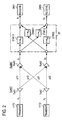
- the paths from the transmitting antenna element TxA1 to the receiving antenna elements RxA1 and RxA2 are indicated by p11 and p12, respectively, and the paths from the transmitting antenna element TxA2 to the receiving antenna elements RxA1 and RxA2 are indicated by p21 and p22, respectively.
- Disposed between the antenna elements RxA1 to RxAN of the receiving antenna RxANT is the N-channel inter-channel interference canceller 20.
- the transfer function p ij of each path ij is given by the following equation (1) wherein a ij and ⁇ ij are attenuation and phase coefficients of the path ij.
- p ij a ij e j ⁇ ij
- x represent transmission signal sequences that are transmission signals x 1 and x 2 from the respective transmitters 11T1 and 11T2
- y represent received signal sequences that are received signals y 1 and y 2 of the respective receiving antennas RxA1 and RxA2
- P represent a transfer function matrix from the transmitting antenna TxANT to the receiving antenna RxANT
- y (y 1 y 2 ) T
- weighting factors of the paths from the receiving antenna element RxA1 to the receivers 20R1 and 20R2 be represented by w 11 and w 12
- weighting factors of the paths from the receiving antenna element RzA2 to the receivers 20R1 and 20R2 by w 21 and w 22
- W weighting factor matrix
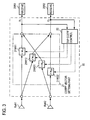
- Figure 3 shows the basic configuration for diagonaliation of the matrix WP in the case where the number N of channels is two.
- the inter-channel interference canceller 20 is provided with a coefficient vector setting part 21 and a tap coefficient controller 22.
- the tap coefficient controller 22 monitors the receiver input signal sequence z(z 1 , z 2 ), and adaptively controls the weighting factor of each path.
- the diagonaliation of a correlation matrix of the signal sequence z permits diagonalization of the matrix WP. That is, for each one of channels the weighting factor matrix W removes signals from those unwanted transmitting antenna elements corresponding to the other channels from the received signal of that channel.
- the correlation matrix can be adaptively diagonalized using a least square estimation method or the like. Such an estimation algorithm is commonly used for adaptive signal processing. The present invention also allows the use of such signal processing.
- N 2 in Fig. 3
- N will herein below be an arbitrary integer equal to or greater than 2.
- the transfer function of a propagation path is unknown.
- the present invention sets the weighting factor matrix W at the receiving side prior to the start of a radio communication. In the first place, all weighting factors are initialized to ones, for instance.
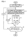
- Figure 4 shows an example of the procedure for diagonalizing the matrix WP by updating the initialized weighting factors w 11 through w NN .
- Step S3 Set the factors w 11 (i) through w NN (i) thus determined in step S2 as updated factors in the factor multipliers 21W11 through 21WNN.
- Step S7 If it is found in step S6 that even one of the absolute values of the non-diagonal elements is not smaller than ⁇ w, reset the value i to 1, then return to step S2, and repeat the factor updating for each transmitter 11Ti.
- the weighting factors w 11 through w NN are updated until the cross correlation elements of the matrix WP reach values below a predetermined design value (for example, 0.01 or below).
- the weighting factor matrix W can also be calculated by one operation from a known transmission signal x and the corresponding received signal z without using an adaptive algorithm. That is, in Equation (9) the weighting factor matrix W is calculated by one operation after transmitting known sequences (training sequences) as transmission signals for weighting factor setting use from the transmitters 11T1 through 11TN and receiving all the signals by the receivers 20R1 through 20RN.
- Figure 5 shows the procedure therefor.
- Step S2 Receive, by the receiving antenna elements RxA1 through RxAN, known training sequences x (x 1 , x 2 , ..., x N ) sequentially sent from the respective transmitters 11T1 through 11TN. More specifically, in the first place, for example, the transmitter 11T1 alone sends a signal, and he receiving antenna elements RxA1 through RxAN receive the transmitted signal.
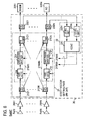
- Figure 6 illustrates in block form a first embodiment of the invention that implements the inter-channel interference canceller 20 in an RF circuit.
- the first embodiment comprises: a receiving antenna RxANT composed of N antenna elements RxA to RxAN; receiving amplifiers LNA1 to LNAN; the inter-channel interference canceller 20; and receivers 20R1 to 20RN.
- the inter-channel interference canceller 20 comprises a coefficient vector setting part 21, a tap coefficient controller 22 and power dividers 23D1 to 23DN.
- the coefficient vector setting part 21 is made up of N power dividers 21D1 to 21DN, N power combiners 21C1 to 21CN and factor multipliers 21W11 to 21WNN inserted in N ⁇ N paths between the N power dividers and the N power combiners.
- Each factor multipliers 21Wij is formed by a variable attenuator 21A and a variable phase shifter 21P.
- the tap coefficient controller 22 is formed by a controller 22C and level detectors 22D1 to 22DN.
- the power divider 23Dj distributes the input signal to the corresponding receiver 20Rj and level detector 22Dj.
- the level detector 22Dj detects the level of the input signal, and provides the detected output to the controller 22C. Based on the levels detected by the level detectors 22D1 to 22DN (which levels correspond to the levels of input signals to the receivers 20R1 to 20RN), the controller 22C follows, for example, the procedure described previously with reference to Fig. 4, by which it controls the variable attenuator 21A and the variable phase shifter 21P of the factor multiplier 21Wij in each path pij.
- Figure 7 illustrates in block form a second embodiment that implements the inter-channel interference canceller 20 through digital signal processing.
- the inter-channel interference canceller 20 Inserted between the A/D converters 25AD1 to 25ADN and the detectors 32D1 to 32DN of the receivers 20R1 to 20RN is the inter-channel interference canceller 20, whose construction is identical with that in the case of Fig. 5.
- the signals distributed by the power dividers 23D1 to 23DN are level detected by the level detectors 22D1 to 22DN.
- the controller 22C follows, for example, the procedure of Fig. 4, by which it determines the weighting factors w 11 to w NN .
- Each power combiner 21Ci may be a digital adder.
- Figure 8 shows an example of updating the weighting factors through the use of training sequences.
- the transmitting side has a training sequence generator 11TS for generating, as training sequences, pseudo-random noise codes or sequences (PN sequences) of excellent orthogonality, such as M-sequences, and a switch 11S.
- the training sequences are provided via the switch 11S to the transmitters 11T1 and 11T2, from which they are sequentially transmitted.
- the inter-channel interference canceller 20 at the receiving side is made up of a switch 21S for turning ON/OFF the outputs from the antenna elements RxA1 and RxA2, a coefficient vector setting part 21 and a tap coefficient controller 22.
- the switch 21S selects one of channels of the receiving antenna elements RxA1 and RxA2, and inputs the received signal to the corresponding channel of the coefficient vector setting part 21 formed by the factor multipliers 21W11 to 21W22 of 2 ⁇ 2 paths.
- the tap coefficient controller 22 comprises correlation detectors 22CD1 and 22CD2 for correlation-detecting the input signals z 1 and z 2 to the receivers 20R1 and 20R2, and a training sequence generator 22TS for supplying the correlation detectors 22CD1 and 22CD2 with the same training sequences as those transmitted.
- the output from the training sequence generator 11TS of the transmitting side is fed via the switch 11S first to the transmitter 11 T1.
- the transmitter 11T1 converts the training sequence to the transmitting frequency band through predetermined modulation.
- the output from the transmitter 11T1 is fed to the first element TxA1 of the transmitting antenna TxANT.
- the training sequence sent from the first element TxA1 is attenuated and phase-rotated by space and received by the receiving antenna RxANT.
- the factor multipliers 21W11 to 21W22 there are preset, for example, ones as initial values of the weighting factors w 11 , w 12 , w 21 and w 22 .
- the first element RxA1 of the receiving antenna is selected by the receiving switch 21S, and the received training sequence is weighted by the factor multiplier 21W11 to an initial value 1.
- the thus weighted training sequence is provided to the correlation detector 22CD1, which obtain a correlation value ⁇ 11 2 by detecting the correlation between the input weighted training sequence and the training sequence which is generated by the training sequence generator 22TS and which is identical with the transmitted training sequence.
- the correlation value ⁇ 11 2 thus obtained is stored in the controller 22C.
- the switch 11S of the transmitting side is held intact and the receiving antenna switch 21S is switched so that the training sequence transmitted from the transmitting antenna element RxA1 is received by the second element RxA2 of the receiving antenna.
- the received training sequence is weighted by the factor multiplier 21W22 to the initial value 1, and the weighted training sequence is provided to the correlation detector 22CD2, which detects a correction value ⁇ 12 2 between the weighted training sequence and the training sequence from the training sequence generator 22TS.
- the correlation value ⁇ 12 2 is stored in the controller 22C.
- the transmitter 11T2 is selected by the switch 11S, and as is the case with the transmitter 11T1, the training sequence sent from the transmitter 11T2 is received by the first element RxA1 of the receiving antenna RxANT, then the received signal is selected by the switch 21S and is provided via the factor multiplier 21W11 to the correlation detector 22CD1 to detect a correlation value ⁇ 21 2 between the received signal and the training sequence, and the correlation value ⁇ 21 2 is stored in the controller 22C.
- the received signal by the second element RxA2 of the receiving antenna, selected by the switch 21S is provided via the factor multiplier 21W22 to the correlation detector 22DC to detect the correlation between the received signal and the training sequence, and the thus obtained correlation value ⁇ 22 2 is stored in the controller 22C.
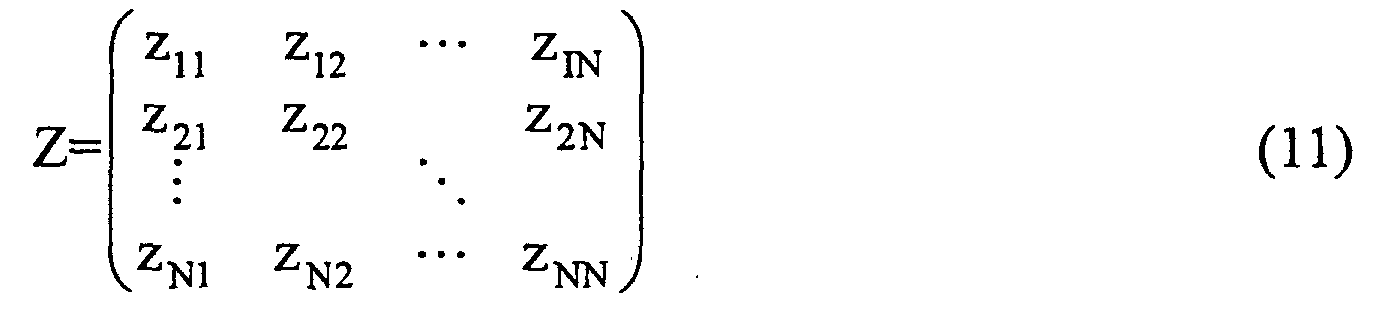
- a 2 ⁇ 2 received signal correlation matrix is obtained which is composed of the correlation values ⁇ 11 2 , ⁇ 12 2 , ⁇ 21 2 , ⁇ 22 2 as its elements.
- the correlation matrix is diagonalized by sequentially updating the weighting factors w 11 , w 12 , w 21 and 22 from the initial value by an adaptive algorithm so that the cross correlation elements ⁇ 12 2 and ⁇ 21 2 of the correlation matrix approach zero.
- the weighting factors w 11 , w 12 , w 21 and w 22 updated upon completion of diagonalization of the correlation matrix are final weighting factors.
- the use of, for example, the M sequence of excellent orthogonality as the training sequence allows ease in detecting the training sequence at the receiving side.
- the training sequence generator 11TS While in the above the training sequence generator 11TS generates identical training sequences and provides them to the transmitters 11T1 and 11Ts, it is also possible that different orthogonal first and second training sequences are provided to the transmitters 11T1 and 11T2 and transmitted therefrom at the same time.
- the training sequence generator 22TS of the receiving side also generates the same first and second training sequences as those at the transmitting side, and provides them to the correlation detectors 22CD1 and 22CD2, respectively.
- the receiving antenna first selects the first element RxA1 by the switch 21S, and provides the received signals via the factor multipliers 21W11 and 21W12 to the correlation detectors 22CD1 and 22CD2, respectively.
- the correlation detectors 22CD1 and 22CD2 obtain the correlation values ⁇ 11 2 and ⁇ 12 2 between the received signals and the first and second training sequences from the training sequence generator 22TS, and the thus obtained correlation values ⁇ 12 2 and ⁇ 21 2 are stored in the controller 22C.
- the second element RxA2 of the receiving antenna is selected by the antenna switch 21S, and the received signals are provided via the factor multipliers 21W21 and 21W22 to the correlation detectors 22CD 1 and 22CD2 to obtain the correlation values ⁇ 21 2 and ⁇ 22 2 , which are stored in the controller 22C.
- a correlation matrix is obtained which is composed of four correlation values as its elements.
- the controller 22C updates weighting factors w 11 , w 12 , w 21 and w 22 sequentially from their initial values by an adaptive algorithm so that the correlation matrix is diagonalized. Such diagonalization of the correlation matrix of the received signals permits space multiplexing corresponding to the number of array antenna elements using the same frequency.
- N transmission signals are spatially multiplexed at the same frequency.
- Fig. 1 Its basic transmitting-receiving system is that shown in Fig. 1.
- the N transmitters 11T1 to 11TN independently generate transmission signals, and transmit them from the respective elements of the transmitting antenna at the same carrier frequency.
- the coefficient vector setting part 21 which generates an inverse transfer characteristic of the spatial transfer function of the receiving system, is so preset as to diagonalize the correlation matrix of the received signals by the training sequence. This enables the signals received by the N-element antenna to be separated into individual signals by the inverse spatial transfer functions implemented by the coefficient vector setting part 21. It is evident, therefore, that complete diagonalization of the correlation matrix could realize an N-fold increase in the frequency utilization efficiency.
- a correlation matrix R zz of a receiver input signal sequence z is given by the following equation (13).
- H indicates a complex conjugate transposition.
- Equation (13) a desired to interference power ratio ⁇ m for each m-th received sequence can be obtained as follows:
- the denominator of Equation (14) becomes zero and the desired to interference power ratio ⁇ m for each m-th received sequence becomes infinity. That is, interference is cancelled by the inverse transfer matrix.
- the amount of information transmitted to the N-channel receiving antenna at this time is the sum of the amounts of information transmitted in the respective channels. For instance, if the amounts of information transmitted in the respective channels are the same, the total amount of information transmitted is N-fold.
- the frequency utilization efficiency by the present invention is based on the diagonalization of Equation (13).
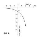
- the transfer function between the transmitting and receiving antennas may sometimes dynamically vary due to fading. Further, in practice, there are cases where the inverse transfer function cannot be obtained. In view of this, a description will be given of an embodiment of the present invention in the case of incomplete diagonalization.
- the abscissa represents the interference power ratio ⁇ m expressed as Equation (14) and the ordinate represents the code error rate in an uncoded QPSK through a static channel where the signal to noise power ratio is infinite. If the desired to interference power ratio ⁇ m is 5 dB, the code error rate can be made about 1%.
- the code error rate becomes approximately 10 -5 .
- the code error rate goes beyond 10%.
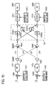
- the above can be achieved by increasing the orthogonality between transmitting channels through the use of orthogonal codes therein.
- the pieces of data d 1 and d 2 to be sent are multiplied in multipliers 13M1 and 13M2 by orthogonal codes from orthogonal code generators 12C1 and 12C2, and the multiplied outputs are input to the transmitters 11T1 and 11T2.
- correlators 27C1 and 27C2 at the inputs of the receivers 20R1 and 20R2, and the correlators 27C 1 and 27C2 detect the correlation between orthogonal codes from orthogonal code generators 29C1 and 29C2 and the received signals, by which the input signals z 1 and z 2 superimposed on the orthogonal codes are separated.
- This is an application of the spread spectrum communication method to the present invention. By this, it is possible to obtain a spreading gain based on the sequence length of the orthogonal code, allowing excellent communication even if interference between channels remains uncancelled.
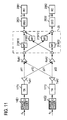
- Figure 11 depicts an example that similarly employs an error correcting code.
- the pieces of input data d 1 and d 2 to be sent are encoded by error correcting coders 14E1 and 14E2 to error correcting codes, which are transmitted from the transmitters 11T1 and 11T2.
- respective channel outputs from the inter-channel interference canceller 20 are decoded by error correcting decoders 28D1 and 28D2 to obtain the received signals z 1 and z 2 , which are applied to the receivers 20R1 and 20R2, respectively.
- the coders 14E1, 14E2 and the decoders 28D1, 28D2 may be those used commonly. For example, a convolution coder and a maximum likelihood sequence estimator may be used in combination.
- the code error rate to the desired to interference power ratio can be improved by the coding gain.
- the use of the correcting code permits excellent communication even if inter-channel interference remains uncancelled.
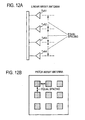
- the transmitting antenna in this case is, for example, a 4-element array antenna, and as depicted in Fig. 12A, the transmitting antenna elements TxA1 to TxA4 are arranged in a geometrical form. Assume, for brevity sake, that the receiving antenna is identical with the transmitting antenna.
- the inverse coefficient matrix that is generated at the receiving side is determined by the path difference between known signal sequences transmitted from the respective transmitting antenna elements and received by the respective receiving antenna elements. This path difference is the phase difference corresponding to Equation (1).
- the transmitting array antenna and the receiving array antenna may also be patch antennas as depicted in Fig. 12B.
- the phase difference between the respective elements can be made large equivalently--this facilitates detection of the phase difference at the receiving side.
- the transmitting and receiving antennas may be, for instance, array antennas of geometric form in which the elements are equally spaced.
- the principles of the present invention have been described on the assumption that the number of transmitting channels and the number of receiving channel are equal.
- the number of receiving channels may be larger than the number of transmitting channels. The reason for this is that when the number of independent receiving channels is larger than the number of transmitting channels, the tap coefficient matrix to be set in the channel canceller can be calculated mathematically.
- the received signals of the respective channels can be separated. This permits multiplex transmission of signals of plural channels at the same frequency from the transmitting side, providing increased frequency utilization efficiency.
Landscapes
- Physics & Mathematics (AREA)
- Mathematical Physics (AREA)
- Engineering & Computer Science (AREA)
- Computer Networks & Wireless Communication (AREA)
- Signal Processing (AREA)
- Radio Transmission System (AREA)
- Variable-Direction Aerials And Aerial Arrays (AREA)
Abstract
Description





Claims (20)
- An N-channel space multiple radio communication method comprising the steps of:(a) generating transmission signals of N channels frequency converted to the same transmitting frequency by N independent transmitters, said N being an integer equal to or greater than 2, and providing said transmission signal of said N channels to N elements of a transmitting antenna for transmission therefrom; and(b) receiving said transmission signals of said N channels by N elements of a receiving antenna, respectively, to generate received signals of N channels, and reconstructing said transmission signals by minimizing the cross correlation between said received signals of said N channels.
- The method of claim 1, wherein: said step (a) includes a step of transmitting a training sequence; and said step (b) includes a step of receiving said training sequence by an N-element antenna, converging weighting factors to thereby minimize said cross correlation coefficient between said received signals of said N channels.
- The method of claim 1, wherein said step (b) comprises the steps of:(b-1) dividing said received signal of each channel to N signals;(b-2) multiplying said each of said N divided signals by a weighting factor;(b-3) generating combined signals of N channels by combining said multiplied signals of said N channels respectively corresponding to said N elements of said receiving antenna; and(b-4) monitoring said N-channel combined signals, determining said weighting factors by an algorithm that minimizes the correlation between said monitored N-channel combined signals, thereby minimizing the cross correlation coefficient between said received signals of said N channels.
- The method of claim 1, wherein said step comprises the steps of:(b-1) frequency converting N-channel received signals from said N elements to N-channel low-frequency signals;(b-2) converting said N-channel low-frequency signals to N-channel digital signals;(b-3) dividing said N-channel digital signals to N signals, respectively, to generate digital signals of N×N paths, and weighting said digital signals of said N×N paths by weighting factors, respectively, to generate weighted digital signals of N×N paths;(b-4) combining said weighted digital signals of said N×N paths for every N signals corresponding to said N channels to generate N digital combined signals as signals corresponding to said received signals of said N-channels; and(b-5) determining said weighting factors of said N×N paths.
- The method of any one of claims 1 to 4, wherein: said step (a) includes a step of modulating each transmission signal by a difference orthogonal code; and said step (b) includes a step of reconstructing each transmission signal by minimizing the correlation between said different orthogonal codes.
- The method of claim 2, wherein: said step (a) is a step of transmitting said training sequence sequentially from said N elements of said transmitting antenna; and said step (b) is a step of determining said weighting factors by an adaptive algorithm that maximizes the level of said combined signal of the channel corresponding to the element having transmitted said training sequence and minimizes the levels of said combined signals of the other channels.
- The method of claim 2, wherein upon each transmission of said training sequence, correlation values between said N-channel combined signals and a predetermined PN sequence, then an N×N received signal correlation matrix is generated using said correlation values, and said weighting factors are determined so that said correlation matrix is diagonalized.
- The method of any one of claims 1 to 4, wherein: said step (a) is a step of coding each transmission signal by a different error correcting code; and said step (b) includes a step of performing decoding concerning said error correcting code to reconstruct said each transmission signal.
- A radio communication apparatus comprising:N independent transmitters, said N being an integer equal to or greater than 2;a transmitting antenna provided with N elements which are supplied with N transmitter outputs, respectively;a receiving antenna provided with N elements;an inter-channel interference canceller, supplied with the outputs from said N elements of said receiving antenna, for generating inverse functions of spatial transfer functions between said n elements of said transmitting antenna and said N elements of said receiving antenna; andN receivers for receiving the respective outputs from said inter-channel interference canceller.
- The apparatus of claim 9, wherein the element spacing of at least one of said transmitting antenna provided with said N elements and said receiving antenna provided with said N elements is constant.
- The apparatus of claim 9 or 10, wherein said inter-channel interference canceller comprising:a power divider for dividing the input signal thereto to N signals;N2 weighting factor multipliers for multiplying said N divided signals by controlled weighted factors, respectively;N power combiners which are supplied with the outputs from said N weighting factor multipliers;N correlation detectors for monitoring the outputs from said N power combiners and for correlation detecting monitored signals; anda controller supplied with the outputs from said N correlation detector, for controlling said N2 weighting factor multipliers.
- The apparatus of claim 9, wherein each of said N receivers comprises:a frequency converter for frequency converting N-channel received signals from said N elements to N-channel low-frequency signals;an A/D converter for converting said N-channel low-frequency signals to N-channel digital signals;N power dividers for dividing said N-channel digital signals to digital signals of N×N paths;weighting factor multipliers for weighting said digital signals of said N×N paths by weighting factors, respectively, to generate weighted digital signals of N×N paths;N power combiners for combining said weighted signals of said N×N paths for every N corresponding to said N channels to obtain N-channel digital combined signals as signals corresponding to said N-channel received signals; anda controller for determining the weighting factors of said N×N paths so that the cross correlation coefficient between said N-channel digital signals is minimized.
- A method for receiving N-channel space multiplex signals transmitted from N elements of a transmitting antenna, said method comprising the steps of:(a) receiving N-channel transmitted signals by N elements of a receiving antenna to generate N-channel received signals;(b) dividing each of said N-channel received signals to obtain signals of N×N paths, then weighting said signals of said N×N paths by weighting factors, respectively, and combining said weighted signals for every N channels to obtain N-channel combined signals; and(c) monitoring said N-channel combined signals, and reconstructing said N-channel transmitted signals by setting said weighting factors so that the cross correlation between said N-channel received signals is minimized.
- The receiving method of claim 13, wherein said step (b) includes the steps of:(b-1) frequency converting said N-channel received signals from said N elements to N-channel low-frequency signals;(b-2) converting said N-channel low-frequency signals to N-channel digital signals;(b-3) dividing said N-channel digital signals to digital signals of N×N paths, and weighting said digital signals of said N×N paths by weighting factors to generate weighted digital signals of N×N paths;(b-4) combining said weighted digital signals of said N×N paths for every N signals corresponding to said N channels to obtain N digital combined signals as signals corresponding to said N-channel received signals; and(b-5) determining said weighting factors of said N×N paths so that the cross correlation coefficient between said N-channel digital signals is minimized.
- The receiving method of claim 13 or 14, wherein said step (b) includes a step of reconstructing each transmission signal by minimizing the correlation concerning orthogonal codes.
- The receiving method of claim 13 or 14, wherein said step (b) includes a step of performing decoding concerning an error correcting code to reconstruct said each transmission signal.
- An apparatus for receiving N-channel transmitted signals from N elements of a transmitting antenna, said apparatus comprising:a receiving antenna provided with N elements, said N being an integer equal to or greater than 2;an N-input-N-output inter-channel interference canceller supplied with N-channel received signals from said N elements of said receiving antenna, for dividing said N-channel received signals to N signals of N×N paths, for weighting said divided N signals of said N×N paths, for combining said weighted N signals for every N channels to generate N-channel combined signals, and for controlling, based on said N-channel combined signals, said weighting factors so that the cross correlation between said N-channel received signals is minimized; andN receivers supplied with respective outputs from said inter-channel interference canceller.
- The receiving apparatus of claim 17, wherein the element spacing of said receiving antenna provided with said N elements is constant.
- The receiving apparatus of claim 17 or 18, wherein said inter-channel interference canceller comprises:a power divider for dividing the input signal thereto to N signals;N2 weighting factor multipliers for multiplying said N divided signals by controlled weighted factors, respectively;N power combiners which are supplied with the outputs from said N weighting factor multipliers;N correlation detectors for monitoring the outputs from said N power combiners and for correlation detecting monitored signals; anda controller supplied with the outputs from said N correlation detector, for controlling said N2 weighting factor multipliers.
- The receiving apparatus of claim 17, wherein each of said N receivers comprises:a frequency converter for frequency converting N-channel received signals from said N elements to N-channel low-frequency signals;an A/D converter for converting said N-channel low-frequency signals to N-channel digital signals;N power dividers for dividing said N-channel digital signals to digital signals of N×N paths;weighting factor multipliers for weighting said digital signals of said N×N paths by weighting factors, respectively, to generate weighted digital signals of N×N paths;N power combiners for combining said weighted signals of said N×N paths for every N corresponding to said N channels to obtain N-channel digital combined signals as signals corresponding to said N-channel received signals; anda controller for determining the weighting factors of said NxN paths so that the cross correlation coefficient between said N-channel digital signals is minimized.
Applications Claiming Priority (2)
| Application Number | Priority Date | Filing Date | Title |
|---|---|---|---|
| JP2000151493 | 2000-05-23 | ||
| JP2000151493 | 2000-05-23 |
Publications (3)
| Publication Number | Publication Date |
|---|---|
| EP1158695A2 true EP1158695A2 (en) | 2001-11-28 |
| EP1158695A3 EP1158695A3 (en) | 2002-12-04 |
| EP1158695B1 EP1158695B1 (en) | 2008-08-06 |
Family
ID=18657044
Family Applications (1)
| Application Number | Title | Priority Date | Filing Date |
|---|---|---|---|
| EP01111983A Expired - Lifetime EP1158695B1 (en) | 2000-05-23 | 2001-05-22 | Space multiplex radio communication method and apparatus |
Country Status (4)
| Country | Link |
|---|---|
| US (1) | US7072409B2 (en) |
| EP (1) | EP1158695B1 (en) |
| CN (1) | CN1184831C (en) |
| DE (1) | DE60135183D1 (en) |
Cited By (5)
| Publication number | Priority date | Publication date | Assignee | Title |
|---|---|---|---|---|
| WO2004049593A1 (en) * | 2002-11-26 | 2004-06-10 | Koninklijke Philips Electronics N.V. | Apparatus, module and computer program for minimizing correlation between received signals |
| WO2004084447A2 (en) | 2003-03-17 | 2004-09-30 | Zyray Wireless, Inc. | Multi-antenna communication systems utilizing rf-based and baseband signal weighting and combining |
| US7187949B2 (en) | 2001-01-19 | 2007-03-06 | The Directv Group, Inc. | Multiple basestation communication system having adaptive antennas |
| EP2442458A1 (en) * | 2010-10-18 | 2012-04-18 | Ntt Docomo, Inc. | Method and receiver for recovering a desired signal transmitted in the presence of one or more interference signals |
| EP2547004A3 (en) * | 2003-07-21 | 2013-04-10 | Broadcom Corporation | Weight generation method for multi-antenna communication systems utilizing RF-based and baseband signal weighting and combining based upon minimum bit error rate |
Families Citing this family (23)
| Publication number | Priority date | Publication date | Assignee | Title |
|---|---|---|---|---|
| US7342875B2 (en) * | 2000-11-06 | 2008-03-11 | The Directv Group, Inc. | Space-time coded OFDM system for MMDS applications |
| CN1150709C (en) * | 2001-02-28 | 2004-05-19 | 信息产业部电信传输研究所 | Spread spectrum and despread method with two-stage code-variable chip rate in CDMA cellular system |
| AU2003201162A1 (en) * | 2002-01-04 | 2003-07-15 | Nokia Corporation | High rate transmit diversity transmission and reception |
| US7986742B2 (en) | 2002-10-25 | 2011-07-26 | Qualcomm Incorporated | Pilots for MIMO communication system |
| US8208364B2 (en) | 2002-10-25 | 2012-06-26 | Qualcomm Incorporated | MIMO system with multiple spatial multiplexing modes |
| US8320301B2 (en) | 2002-10-25 | 2012-11-27 | Qualcomm Incorporated | MIMO WLAN system |
| US20040081131A1 (en) | 2002-10-25 | 2004-04-29 | Walton Jay Rod | OFDM communication system with multiple OFDM symbol sizes |
| KR100571862B1 (en) * | 2003-02-17 | 2006-04-17 | 삼성전자주식회사 | Mobile communication system including multiple antennas and method thereof |
| US8185075B2 (en) | 2003-03-17 | 2012-05-22 | Broadcom Corporation | System and method for channel bonding in multiple antenna communication systems |
| US9473269B2 (en) | 2003-12-01 | 2016-10-18 | Qualcomm Incorporated | Method and apparatus for providing an efficient control channel structure in a wireless communication system |
| US7277731B2 (en) * | 2003-12-23 | 2007-10-02 | Motorola, Inc. | Adaptive diversity antenna system |
| US20050141459A1 (en) * | 2003-12-29 | 2005-06-30 | Intel Corporation | Apparatus and associated methods to reduce management overhead in a wireless communication system |
| US7710925B2 (en) * | 2004-06-23 | 2010-05-04 | Intel Corporation | Spatial puncturing apparatus, method, and system |
| US8045599B2 (en) | 2005-02-17 | 2011-10-25 | Sony Corporation | Selection of training sequences for multiple-in multiple-out transmissions |
| GB2423441A (en) * | 2005-02-22 | 2006-08-23 | Cambridge Silicon Radio Ltd | Reducing signal paths required in an antenna diversity system |
| US20080273452A1 (en) * | 2007-05-04 | 2008-11-06 | Farooq Khan | Antenna mapping in a MIMO wireless communication system |
| US20090323777A1 (en) * | 2008-06-26 | 2009-12-31 | Yi-Pin Eric Wang | Methods and Apparatus for Sharing Signal Correlation Data in a Receiver |
| GB0908825D0 (en) * | 2009-05-21 | 2009-07-01 | Cambridge Silicon Radio Ltd | Antenna selection |
| US8582618B2 (en) * | 2011-01-18 | 2013-11-12 | Avago Technologies General Ip (Singapore) Pte. Ltd. | Surface-emitting semiconductor laser device in which an edge-emitting laser is integrated with a diffractive or refractive lens on the semiconductor laser device |
| US9967028B2 (en) * | 2014-10-22 | 2018-05-08 | Indian Institute Of Technology Delhi | System and a method for free space optical communications |
| WO2020191054A1 (en) * | 2019-03-18 | 2020-09-24 | Georgia Tech Research Corporation | Systems and methods for general-purpose, high-performance transversal filter processing |
| TWI730378B (en) * | 2019-08-15 | 2021-06-11 | 瑞昱半導體股份有限公司 | Detector circuit and operation method |
| CN112564943A (en) * | 2020-11-20 | 2021-03-26 | 北京邮电大学 | Data transmission method, system and medium based on multiple network nodes |
Family Cites Families (6)
| Publication number | Priority date | Publication date | Assignee | Title |
|---|---|---|---|---|
| US5634199A (en) * | 1993-04-14 | 1997-05-27 | Stanford University | Method of subspace beamforming using adaptive transmitting antennas with feedback |
| US5553062A (en) * | 1993-04-22 | 1996-09-03 | Interdigital Communication Corporation | Spread spectrum CDMA interference canceler system and method |
| EP0931388B1 (en) * | 1996-08-29 | 2003-11-05 | Cisco Technology, Inc. | Spatio-temporal processing for communication |
| FI105517B (en) * | 1996-10-18 | 2000-08-31 | Nokia Networks Oy | Reception procedure and recipients |
| US5781845A (en) * | 1996-12-03 | 1998-07-14 | The Aerospace Corporation | Adaptive transmitting antenna |
| US6549565B1 (en) * | 1999-12-07 | 2003-04-15 | Lucent Technologies Inc. | Code division multiple access system and method of operation with improved signal acquisition and processing |
-
2001
- 2001-05-22 EP EP01111983A patent/EP1158695B1/en not_active Expired - Lifetime
- 2001-05-22 DE DE60135183T patent/DE60135183D1/en not_active Expired - Lifetime
- 2001-05-22 US US09/861,717 patent/US7072409B2/en not_active Expired - Fee Related
- 2001-05-23 CN CN01122090.2A patent/CN1184831C/en not_active Expired - Fee Related
Cited By (7)
| Publication number | Priority date | Publication date | Assignee | Title |
|---|---|---|---|---|
| US7187949B2 (en) | 2001-01-19 | 2007-03-06 | The Directv Group, Inc. | Multiple basestation communication system having adaptive antennas |
| WO2004049593A1 (en) * | 2002-11-26 | 2004-06-10 | Koninklijke Philips Electronics N.V. | Apparatus, module and computer program for minimizing correlation between received signals |
| WO2004084447A2 (en) | 2003-03-17 | 2004-09-30 | Zyray Wireless, Inc. | Multi-antenna communication systems utilizing rf-based and baseband signal weighting and combining |
| EP1606916A4 (en) * | 2003-03-17 | 2011-10-26 | Broadcom Corp | Multi-antenna communication systems utilizing rf-based and baseband signal weighting and combining |
| US8693577B2 (en) | 2003-03-17 | 2014-04-08 | Broadcom Corporation | Multi-antenna communication systems utilizing RF-based and baseband signal weighting and combining |
| EP2547004A3 (en) * | 2003-07-21 | 2013-04-10 | Broadcom Corporation | Weight generation method for multi-antenna communication systems utilizing RF-based and baseband signal weighting and combining based upon minimum bit error rate |
| EP2442458A1 (en) * | 2010-10-18 | 2012-04-18 | Ntt Docomo, Inc. | Method and receiver for recovering a desired signal transmitted in the presence of one or more interference signals |
Also Published As
| Publication number | Publication date |
|---|---|
| DE60135183D1 (en) | 2008-09-18 |
| EP1158695A3 (en) | 2002-12-04 |
| EP1158695B1 (en) | 2008-08-06 |
| CN1325243A (en) | 2001-12-05 |
| CN1184831C (en) | 2005-01-12 |
| US7072409B2 (en) | 2006-07-04 |
| US20020003842A1 (en) | 2002-01-10 |
Similar Documents
| Publication | Publication Date | Title |
|---|---|---|
| EP1158695B1 (en) | Space multiplex radio communication method and apparatus | |
| EP1320212B1 (en) | Method and apparatus for frequency multiplexing with interference cancellation | |
| US7248645B2 (en) | Wireless transmission using an adaptive transmit antenna array | |
| US6987819B2 (en) | Method and device for multiple input/multiple output transmit and receive weights for equal-rate data streams | |
| EP1287627B1 (en) | Closed loop feedback system for improved down link performance | |
| KR100365789B1 (en) | Parallel hopping direct sequence/slow frequency hopping composite cdma system | |
| US6167039A (en) | Mobile station having plural antenna elements and interference suppression | |
| US7164725B2 (en) | Method and apparatus for antenna array beamforming | |
| US6564037B1 (en) | Multi-user detection for antenna array receivers | |
| EP1265378B1 (en) | Adaptive antenna array | |
| EP1359683A1 (en) | Wireless communication using multi-transmit multi-receive antenna arrays | |
| CN101563849B (en) | Fluctuating transmission pattern to support signal separation at the receiver | |
| EP1341315A1 (en) | A spatial matched filtering method and array receiver in radio communication system | |
| EP1179229B1 (en) | A method and apparatus for antenna array beamforming | |
| US7535970B2 (en) | Wireless communication apparatus and method for multiple transmit and receive antenna system using multiple codes | |
| US20070142004A1 (en) | Radio communication apparatus and method | |
| CN101167257A (en) | Method for generating weights for multi-antenna communication systems using weighted combination of radio frequency and baseband signals based on minimum bit error rate | |
| JP4091270B2 (en) | Spatial multiplexing wireless communication method and wireless communication apparatus | |
| WO2005002067A2 (en) | Multi-carrier spread spectrum using non-linear modification of sub-carrier bands | |
| RU2262198C1 (en) | Signal transfer method and device for realization of said method | |
| EP1511187A2 (en) | Transmission power control for multiple codes multiple antennas system | |
| Tsouri et al. | Selection combining upgrade schemes for mobile units in wireless networks |
Legal Events
| Date | Code | Title | Description |
|---|---|---|---|
| PUAI | Public reference made under article 153(3) epc to a published international application that has entered the european phase |
Free format text: ORIGINAL CODE: 0009012 |
|
| 17P | Request for examination filed |
Effective date: 20010522 |
|
| AK | Designated contracting states |
Kind code of ref document: A2 Designated state(s): AT BE CH CY DE DK ES FI FR GB GR IE IT LI LU MC NL PT SE TR |
|
| AX | Request for extension of the european patent |
Free format text: AL;LT;LV;MK;RO;SI |
|
| PUAL | Search report despatched |
Free format text: ORIGINAL CODE: 0009013 |
|
| AK | Designated contracting states |
Kind code of ref document: A3 Designated state(s): AT BE CH CY DE DK ES FI FR GB GR IE IT LI LU MC NL PT SE TR |
|
| AX | Request for extension of the european patent |
Free format text: AL;LT;LV;MK;RO;SI |
|
| AKX | Designation fees paid |
Designated state(s): DE FR GB IT SE |
|
| GRAP | Despatch of communication of intention to grant a patent |
Free format text: ORIGINAL CODE: EPIDOSNIGR1 |
|
| GRAS | Grant fee paid |
Free format text: ORIGINAL CODE: EPIDOSNIGR3 |
|
| GRAA | (expected) grant |
Free format text: ORIGINAL CODE: 0009210 |
|
| AK | Designated contracting states |
Kind code of ref document: B1 Designated state(s): DE FR GB IT SE |
|
| REG | Reference to a national code |
Ref country code: GB Ref legal event code: FG4D |
|
| REF | Corresponds to: |
Ref document number: 60135183 Country of ref document: DE Date of ref document: 20080918 Kind code of ref document: P |
|
| REG | Reference to a national code |
Ref country code: SE Ref legal event code: TRGR |
|
| PLBE | No opposition filed within time limit |
Free format text: ORIGINAL CODE: 0009261 |
|
| STAA | Information on the status of an ep patent application or granted ep patent |
Free format text: STATUS: NO OPPOSITION FILED WITHIN TIME LIMIT |
|
| 26N | No opposition filed |
Effective date: 20090507 |
|
| PGFP | Annual fee paid to national office [announced via postgrant information from national office to epo] |
Ref country code: DE Payment date: 20130515 Year of fee payment: 13 Ref country code: SE Payment date: 20130513 Year of fee payment: 13 Ref country code: GB Payment date: 20130522 Year of fee payment: 13 |
|
| PGFP | Annual fee paid to national office [announced via postgrant information from national office to epo] |
Ref country code: IT Payment date: 20130515 Year of fee payment: 13 Ref country code: FR Payment date: 20130531 Year of fee payment: 13 |
|
| REG | Reference to a national code |
Ref country code: DE Ref legal event code: R119 Ref document number: 60135183 Country of ref document: DE |
|
| GBPC | Gb: european patent ceased through non-payment of renewal fee |
Effective date: 20140522 |
|
| PG25 | Lapsed in a contracting state [announced via postgrant information from national office to epo] |
Ref country code: SE Free format text: LAPSE BECAUSE OF NON-PAYMENT OF DUE FEES Effective date: 20140523 |
|
| REG | Reference to a national code |
Ref country code: SE Ref legal event code: EUG |
|
| REG | Reference to a national code |
Ref country code: FR Ref legal event code: ST Effective date: 20150130 |
|
| REG | Reference to a national code |
Ref country code: DE Ref legal event code: R119 Ref document number: 60135183 Country of ref document: DE Effective date: 20141202 |
|
| PG25 | Lapsed in a contracting state [announced via postgrant information from national office to epo] |
Ref country code: DE Free format text: LAPSE BECAUSE OF NON-PAYMENT OF DUE FEES Effective date: 20141202 Ref country code: IT Free format text: LAPSE BECAUSE OF NON-PAYMENT OF DUE FEES Effective date: 20140522 |
|
| PG25 | Lapsed in a contracting state [announced via postgrant information from national office to epo] |
Ref country code: FR Free format text: LAPSE BECAUSE OF NON-PAYMENT OF DUE FEES Effective date: 20140602 Ref country code: GB Free format text: LAPSE BECAUSE OF NON-PAYMENT OF DUE FEES Effective date: 20140522 |