EP1158692A2 - Method for multipath detection in wireless communication apparatus - Google Patents
Method for multipath detection in wireless communication apparatus Download PDFInfo
- Publication number
- EP1158692A2 EP1158692A2 EP01304537A EP01304537A EP1158692A2 EP 1158692 A2 EP1158692 A2 EP 1158692A2 EP 01304537 A EP01304537 A EP 01304537A EP 01304537 A EP01304537 A EP 01304537A EP 1158692 A2 EP1158692 A2 EP 1158692A2
- Authority
- EP
- European Patent Office
- Prior art keywords
- wireless communication
- communication apparatus
- multipath
- wave
- signal
- Prior art date
- Legal status (The legal status is an assumption and is not a legal conclusion. Google has not performed a legal analysis and makes no representation as to the accuracy of the status listed.)
- Granted
Links
Images



Classifications
-
- H—ELECTRICITY
- H04—ELECTRIC COMMUNICATION TECHNIQUE
- H04B—TRANSMISSION
- H04B1/00—Details of transmission systems, not covered by a single one of groups H04B3/00 - H04B13/00; Details of transmission systems not characterised by the medium used for transmission
- H04B1/69—Spread spectrum techniques
- H04B1/707—Spread spectrum techniques using direct sequence modulation
- H04B1/7097—Interference-related aspects
- H04B1/711—Interference-related aspects the interference being multi-path interference
-
- H—ELECTRICITY
- H04—ELECTRIC COMMUNICATION TECHNIQUE
- H04B—TRANSMISSION
- H04B7/00—Radio transmission systems, i.e. using radiation field
- H04B7/005—Control of transmission; Equalising
-
- H—ELECTRICITY
- H04—ELECTRIC COMMUNICATION TECHNIQUE
- H04B—TRANSMISSION
- H04B1/00—Details of transmission systems, not covered by a single one of groups H04B3/00 - H04B13/00; Details of transmission systems not characterised by the medium used for transmission
- H04B1/06—Receivers
- H04B1/10—Means associated with receiver for limiting or suppressing noise or interference
- H04B1/1081—Reduction of multipath noise
Definitions
- the present invention generally relates to a wireless communication apparatus and a wireless communication method. More particularly, the present invention relates to a wireless communication apparatus and a wireless communication method in which multipath interference is relieved.
- Fig.1 shows an configuration example of a mobile communication system.
- the mobile communication system includes mobile stations 22 and a base station 23 which are placed in each area.
- an obstacle 24 which reflects radio wave of mobile wireless communication.
- the radio wave is reflected by the obstacle 24 so that the direct wave 25 and the reflected wave 26 arrive at the mobile station 22 via a plurality of paths. This is called multipath.
- the level of received wave in the mobile station varies significantly according to the position of the mobile station due to the interference caused by the multipath. It is known that the interference occurs by wavelength of the wave.
- a space diversity system in which a plurality of antennas which are placed different positions and/or which have different directions are provided for receiving signals.
- a RAKE receive system is adopted in which a plurality of receive circuits are provided such that the phases of the direct wave and the reflected wave are adjusted when they are received.
- the multipath direct wave 25 and the reflected wave 26 shown in Fig.1 are received in different time positions with respect to the time base shown as the direct wave 27 and the reflected wave 28 in Fig.2.
- the direct wave 27 and the reflected wave 28 it becomes possible that a plurality of multipaths can be synthesized and received.
- a wireless communication apparatus including:
- the wireless communication apparatus at the other end can detects a state of multipath in the wireless communication apparatus which sent the multipath detection information and send a multipath component canceling signal.
- a wireless communication apparatus including:
- the present invention it becomes possible to remove or decrease influence of multipath in the wireless communication apparatus at the other end by sending the signal for canceling the multipath component to the wireless communication apparatus at the other end.
- the multipath component canceling signal generation part may includes:
- the multipath component canceling signal can be generated.
- the interference wave detection part may includes:
- the interference wave signal corresponding to an interference wave signal in the wireless communication apparatus of the other end can be generated.
- the above-mentioned wireless communication apparatus may further includes:
- the influence of multipath in the wireless communication apparatus at the other end can be removed or decreased.
- wireless communication apparatus may send an opposite phase wave of the signal which cancels the multipath component at a time position of a multipath having no interference in order to cancel the signal which cancels the multipath component.
- the signal which cancels the multipath component or interference opposite phase wave occurring at a time position of multipath which has no interference can be canceled so that it can be prevented that the multipath component which does not receive interference is attenuated.
- a wireless communication method including the step of: a wireless communication apparatus sending a signal which cancels a multipath component in a wireless communication apparatus at the other end to the wireless communication apparatus at the other end with a send signal.
- the signal which cancels the multipath component is a signal inverted from an interference wave signal generated from the multipath component in the wireless communication apparatus at the other end.
- a wireless communication method which is applicable to the above-mentioned wireless communication apparatus can be provided in which interference due to multipath can be significantly decreased so that signal transmission quality is improved without increasing the size of a mobile station.
- a wireless communication apparatus of the first embodiment is configured as shown in Fig.3 for example.
- the wireless communication apparatus (for example, mobile station) includes a wireless part 1 and a multipath detection part 2 which detects multipath.
- the wireless part 1 receives a radio wave sent by a wireless communication apparatus at the other end (for example, a base station), and provides a received wave 11 to the multipath detection part 2.
- the multipath detection part 2 detects multipath from the received signal provided from the wireless part 1 and provides multipath detection information 12 to the wireless part 1.
- the wireless part 1 sends the multipath detection information provided from the multipath detection part 2 to a wireless communication apparatus at the other end of communication.
- the detection information 12 of the multipath detected by the multipath detection part 2 includes relative delay time of the path, relative level of the path and the like, for example.
- the multipath can be detected by detecting delay time and levels of paths by using path search of the RAKE.
- the wireless communication apparatus of the second embodiment is configured as shown in Fig.4 for example.
- the wireless communication apparatus (for example, the base station) includes a wireless part 1 and a multipath component canceling signal generation circuit part 3.
- the wireless part 1 receives multipath detection information 12 sent from a wireless communication apparatus at the other end of communication (the mobile station, for example) and provides the multipath detection information 12 to the multipath component canceling signal generation circuit part 3.
- the multipath component canceling signal generation circuit part 3 generates a multipath component canceling signal 16 for canceling multipath components from the multipath detection information 12, and provides the multipath component canceling signal 16 to the wireless part 1.
- the wireless part 1 sends the multipath component canceling signal provided by the multipath component canceling signal generation circuit part 3.
- the multipath component canceling signal is sent to the wireless communication apparatus which sent the multipath detection information with a send wave.
- Fig.5 is a figure for explaining generation of an interference wave in the wireless communication apparatus (the base station, for example).
- the wireless communication apparatus includes a send wave generation part 4, a multipath generation part 5, a synthesis part 6 and a comparison part 7.
- the send wave 13 output from the send wave generation part 4 is provided to the multipath generation part 5, the comparison part 7 and the synthesis part 6.
- the multipath generation part 5 generates a multipath wave 14 on the basis of the multipath detection information detected by the mobile station, for example, and provides the multipath wave 14 to the synthesis part 6.
- the synthesis part 6 synthesizes the send wave 13 and the multipath wave 14, and provides the synthesized wave 15 to the comparison part 7.
- the synthesized wave 15 represents a signal which replicates the state of the multipath received by the mobile station.
- the comparison part 7 compares the send wave 13 with the synthesized wave 15, generates an interference wave 18 and outputs the interference wave 18 to a terminal 30.
- the wireless communication apparatus of the third embodiment is configured as shown in Fig.6 for example.
- the wireless communication apparatus (the base station, for example) includes a wireless part 1, a send wave generation part 4, a multipath generation part 5, a synthesis part 6, a comparison part 7, a filter part 8, an opposite phase part 9 and a synthesis part 10.
- the wireless part 1 provides the multipath detection information 12 received from the wireless communication apparatus shown in Fig.3 to the multipath generation part 5.
- the send wave generation part 4 provides the send wave 13 to the multipath generation part 5, the synthesis part 6, the comparison part 7 and the synthesis part 10.
- the multipath generation part 5 generates a multipath wave 14 based on the multipath detection information sent from a wireless communication apparatus at the other end (the mobile station, for example) and provides the multipath wave 14 to the synthesis part 6.
- the synthesis part 6 synthesizes the send wave 13 and the multipath wave 14, and provides the synthesized wave 15 of the send wave 13 and the multipath wave 14 to the filter part 8.
- Fig.7 shows the synthesized wave 15 of the send wave 13 and the multipath wave 14.
- the part (the diagonally shaded area) on which the send wave 13 and the multipath wave 14 overlap one another becomes the interference wave 18.
- the multipath wave 14 has a delay time "a" with respect to the send wave 13.
- the send wave 13 and the multipath wave 14 are filtered to a band of basic waves by the filter part 8.
- the send wave + multipath synthesized wave 17 which is filtered by the filter part 8 is provided to the comparison part 7.
- Fig.9 shows the characteristic 21 of the filter part 8 and output signal from the filter part (send wave + multipath synthesized wave 17).
- the characteristic 21 of the filter part 8 shown in Fig.9 shows filtering for time and frequencies, filtering only for time may be performed. In such a case, although perfect interference wave can not be obtained, it becomes possible to decrease interference caused by the multipath.
- the comparison part 7 compares the send wave + multipath synthesized wave 17 which was filtered by the filter part 8 with the send wave 13 provided by the send wave generation part 4. And, then, the comparison part 7 subtracts the send wave 13 from the send wave + multipath synthesized wave 17 and generates the interference wave 18 and provides the interference wave 18 to the opposite phase part 9.
- Fig.10 shows the interference wave 18 generated by the comparison part 7.
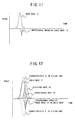
- the opposite phase part 9 changes the phase of the interference wave 18 to opposite phase ,and, as a result, generates an interference signal opposite phase wave 19. Then, the opposite phase part 9 provides the interference signal opposite phase wave 19 to the synthesis part 10. When the interference signal opposite phase wave 19 and the send wave + multipath synthesized wave 17 filtered by the filter part 8 are added, the send wave 13 is restored.
- the synthesis part 10 synthesizes the interference signal opposite phase wave 19 provided from the opposite phase part 9 and the send wave 13 provided from the send wave generation part 4 and provides the interference signal opposite phase wave + send wave 20 to the wireless part 1.
- Fig.11 shows the interference signal opposite phase wave + send wave 20 which is synthesized in the synthesis part 10.
- the wireless part 1 sends the interference signal opposite phase wave + send wave 20 by wireless communication.
- step 1 The wireless communication apparatus shown in Fig.3 sends the multipath detection information detected by the multipath detection part 2 to the wireless communication apparatus at the other end.
- step 2 The wireless communication apparatus shown in Fig.6 receives a signal sent from the wireless communication apparatus shown in Fig.3. Then, the multipath generation part 5 generates multipath component from the multipath detection information indicating multipath state of the wireless communication apparatus shown in Fig.3.
- step 3 The synthesis part 6 synthesizes the multipath component generated by the multipath generation part 5 and the send basic wave generated by the send wave generation part 4.
- the filter part 8 performs filtering in which the signal synthesized by the synthesis part 6 is flittered to a band of basic waves.
- step 5 The comparison part 7 compares the filtered signal with the send wave generated by the send wave generation part 4 and generates the interference wave signal corresponding to that in the wireless communication apparatus shown in Fig.3.
- step 6 The phase of the interference wave signal which is output from the comparison part 7 is changed to opposite phase by the opposite phase part 9.
- step 7 The synthesis part 10 synthesizes the send wave generated by the send wave signal generation part 4 and the interference wave signal in which the phase is changed to opposite by the opposite phase part 9. Then, the wireless part 1 sends the synthesized signal to the wireless communication apparatus shown in Fig.3.
- step 8 The wireless communication apparatus 1 shown in Fig.3 receives signals shown in Fig.12.
- the interference wave 18 and the interference signal opposite phase wave 19 shown in Fig.12 cancel one another.
- a signal can be restored in which the multipath interference is removed so that it becomes possible to receive in good receive condition.
- the closed loop for removing multipath may be performed in which the multipath detection part 2 detects the reflected wave 28 by using a path searcher in the multipath detection part 2 before the wave passes though a filter part 8 in the RAKE of the multipath detection part 2, then, the multipath detection information 12 is sent from the wireless part 1 so that the wireless communication apparatus shown in Fig.6 gets feedback.
- the interference opposite phase wave is generated with respect to the multipath interference wave having delay time "a” as shown in Fig.7.
- multipath interference having delay time other than "a” can be prevented by generating interference opposite phase wave with respect to multipath interference wave having delay time other than "a".
- a multipath which is not interfered becomes a part of received signal after received by RAKE. Thus, it is necessary to prevent that received signal is attenuated due to the interference opposite phase wave for the multipath which is not interfered.
- the wireless communication apparatus shown in Fig.6 sends a wave adding a phase opposite wave of the interference opposite phase wave 19 at a time position of delay time "b" on the basis of notification from the wireless communication apparatus at the other end in order to remove the influence of the interference opposite phase wave.
- the present invention can be applied also to a case in which the mobile station sends a signal and the base station receives it.
- the present invention can be applied to communication between base stations and communication between fixed stations.
Landscapes
- Engineering & Computer Science (AREA)
- Computer Networks & Wireless Communication (AREA)
- Signal Processing (AREA)
- Noise Elimination (AREA)
- Mobile Radio Communication Systems (AREA)
- Radio Transmission System (AREA)
- Monitoring And Testing Of Transmission In General (AREA)
Abstract
Description
a wireless communication apparatus sending a signal which cancels a multipath component in a wireless communication apparatus at the other end to the wireless communication apparatus at the other end with a send signal.
Claims (9)
- A wireless communication apparatus characterized by:a multipath detection part which detects a state of multipath in said wireless communication apparatus; anda send part which sends multipath detection information detected by said multipath detection part to a wireless communication apparatus at the other end.
- A wireless communication apparatus characterized by:a multipath component canceling signal generation part which generates a signal which cancels a multipath component in a wireless communication apparatus at the other end on the basis of multipath detection information representing a state of multipath sent from said wireless communication apparatus at the other end; anda send part which sends said signal which cancels said multipath component generated in said multipath component canceling signal generation part to said wireless communication apparatus at the other end.
- The wireless communication apparatus as claimed in claim 2, said multipath component canceling signal generation part comprising:a multipath component generation part which generates a multipath component on the basis of said multipath detection information representing said state of multipath in said wireless communication apparatus at the other end; andan interference wave detection part which detects an interference wave occurring between said multipath component and a send wave.
- The wireless communication apparatus as claimed in claim 3, said interference wave detection part comprising:a filter part which filters a synthesized wave of said multipath component and said send wave; andan interference wave signal generation part which generates an interference wave signal corresponding to that in said wireless communication apparatus at the other end by comparing output signal from said filter part and said send wave.
- The wireless communication apparatus as claimed in claim 4, further comprising:an opposite phase part which changes a phase of said interference wave signal to an opposite phase of said phase; anda send part which sends said interference wave signal having said opposite phase to said wireless communication apparatus at the other end.
- The wireless communication apparatus as claimed in claim 2, wherein said wireless communication apparatus sends an opposite phase wave of said signal which cancels said multipath component at a time position of a multipath having no interference in order to cancel said signal which cancels said multipath component.
- A wireless communication method characterized by the step of:
a wireless communication apparatus sending a signal which cancels a multipath component in a wireless communication apparatus at the other end to said wireless communication apparatus at the other end with a send signal. - The wireless communication method as claimed in claim 7, wherein said signal which cancels said multipath component is a signal inverted from an interference wave signal generated from said multipath component in said wireless communication apparatus at the other end.
- A wireless communication method characterized by the steps of:a first wireless communication apparatus detecting a state of multipath in said first wireless communication apparatus;said first wireless communication apparatus sending multipath detection information on said state to a second wireless communication apparatus;said second wireless communication apparatus receiving said multipath detection information;said second wireless communication apparatus generating a signal for canceling a multipath component in said first wireless communication apparatus on the basis of said multipath detection information; andsaid second wireless communication apparatus sending said signal for canceling said multipath component to said first wireless communication apparatus.
Applications Claiming Priority (2)
| Application Number | Priority Date | Filing Date | Title |
|---|---|---|---|
| JP2000153688 | 2000-05-24 | ||
| JP2000153688A JP3670555B2 (en) | 2000-05-24 | 2000-05-24 | Wireless communication apparatus and wireless communication method |
Publications (3)
| Publication Number | Publication Date |
|---|---|
| EP1158692A2 true EP1158692A2 (en) | 2001-11-28 |
| EP1158692A3 EP1158692A3 (en) | 2005-11-30 |
| EP1158692B1 EP1158692B1 (en) | 2007-08-01 |
Family
ID=18658899
Family Applications (1)
| Application Number | Title | Priority Date | Filing Date |
|---|---|---|---|
| EP20010304537 Expired - Lifetime EP1158692B1 (en) | 2000-05-24 | 2001-05-23 | Method for multipath detection in wireless communication apparatus |
Country Status (5)
| Country | Link |
|---|---|
| US (1) | US7088977B2 (en) |
| EP (1) | EP1158692B1 (en) |
| JP (1) | JP3670555B2 (en) |
| KR (1) | KR100404978B1 (en) |
| DE (1) | DE60129637T2 (en) |
Families Citing this family (2)
| Publication number | Priority date | Publication date | Assignee | Title |
|---|---|---|---|---|
| US8276425B2 (en) | 2007-10-02 | 2012-10-02 | Mestek Machinery, Inc. | Ductmaking apparatus |
| US10812119B1 (en) * | 2019-06-19 | 2020-10-20 | Nxp B.V. | Systems and methods involving interference cancellation |
Family Cites Families (12)
| Publication number | Priority date | Publication date | Assignee | Title |
|---|---|---|---|---|
| JPS5814064A (en) | 1981-07-17 | 1983-01-26 | Pioneer Electronic Corp | S/n ratio measuring circuit |
| JPS6014524A (en) * | 1983-07-06 | 1985-01-25 | Pioneer Electronic Corp | Multipath distortion reducing circuit |
| JP2672506B2 (en) * | 1987-04-06 | 1997-11-05 | 株式会社東芝 | Digital wireless communication system |
| JPH1079724A (en) * | 1996-09-03 | 1998-03-24 | Toshiba Corp | Wireless communication system |
| JP2760240B2 (en) * | 1992-03-11 | 1998-05-28 | 松下電器産業株式会社 | Noise suppression device |
| US5249233A (en) * | 1992-04-06 | 1993-09-28 | Ford Motor Company | Multipath noise minimizer for radio receiver |
| WO1995034140A1 (en) * | 1994-06-03 | 1995-12-14 | Motorola, Inc. | Method and apparatus for cancelling interference in signals having undergone multipath |
| JP3354286B2 (en) * | 1994-06-04 | 2002-12-09 | 株式会社ケンウッド | Multipass rejection filter |
| US5768254A (en) * | 1995-09-29 | 1998-06-16 | Lucent Technologies Inc. | Multiple access cellular communication with signal cancellation to reduce co-channel interference |
| US5960039A (en) * | 1996-04-10 | 1999-09-28 | Lucent Technologies Inc. | Methods and apparatus for high data rate transmission in narrowband mobile radio channels |
| JP2894340B1 (en) * | 1998-03-04 | 1999-05-24 | 日本電気株式会社 | Spread spectrum communication system |
| JP3185874B2 (en) * | 1998-07-21 | 2001-07-11 | 日本電気株式会社 | Wireless communication system |
-
2000
- 2000-05-24 JP JP2000153688A patent/JP3670555B2/en not_active Expired - Fee Related
-
2001
- 2001-05-22 KR KR10-2001-0028046A patent/KR100404978B1/en not_active Expired - Fee Related
- 2001-05-23 DE DE2001629637 patent/DE60129637T2/en not_active Expired - Lifetime
- 2001-05-23 US US09/862,439 patent/US7088977B2/en not_active Expired - Fee Related
- 2001-05-23 EP EP20010304537 patent/EP1158692B1/en not_active Expired - Lifetime
Also Published As
| Publication number | Publication date |
|---|---|
| EP1158692A3 (en) | 2005-11-30 |
| DE60129637T2 (en) | 2008-05-21 |
| JP2001332990A (en) | 2001-11-30 |
| DE60129637D1 (en) | 2007-09-13 |
| JP3670555B2 (en) | 2005-07-13 |
| EP1158692B1 (en) | 2007-08-01 |
| KR100404978B1 (en) | 2003-11-07 |
| US7088977B2 (en) | 2006-08-08 |
| KR20010107644A (en) | 2001-12-07 |
| US20020006775A1 (en) | 2002-01-17 |
Similar Documents
| Publication | Publication Date | Title |
|---|---|---|
| US7031402B2 (en) | Interference signal removal system | |
| EP1841084B1 (en) | Radio communication apparatus and radio communication method | |
| AU771268B2 (en) | A method of canceling interference based on smart antenna | |
| US20060055594A1 (en) | Method and apparatus for reducing GPS receiver jamming during transmission in a wireless receiver | |
| US6625202B1 (en) | Mobile station for spread spectrum communication | |
| CN103401581B (en) | Mobile station, mobile radio communication system, and mobile radio communication method | |
| GB2508443A (en) | Processing interference in a wireless network | |
| EP2208283B1 (en) | Anti jamming system | |
| JP3989922B2 (en) | High frequency receiving apparatus and method for mobile communication terminal | |
| CA2829021A1 (en) | Spread-spectrum pilot signals in an electronic duplexer | |
| EP1233543A1 (en) | Base station device and radio transmitting method | |
| EP1032135A2 (en) | Method for reducing interference in a receiver | |
| US7088977B2 (en) | Wireless communication apparatus and wireless communication method | |
| US20090295636A1 (en) | Receiving Apparatus, Signal Processing Circuit, and Receiving System | |
| KR100658211B1 (en) | Radio Repeater for Mobile Communication System and Repeating Method Using the Same | |
| KR20010099884A (en) | Adaptive array antenna apparatus and adaptive array antenna apparatus for base stations | |
| JPH07321681A (en) | Interference wave remover | |
| GB2376607A (en) | A method for reducing interference to communications in time division duplexing (TDD) mode between a TDD mobile and a TDD base station | |
| JP2781947B2 (en) | Direct spread spectrum spread communication equipment | |
| KR100807435B1 (en) | Wireless communication system, wireless communication terminal, and wireless communication method | |
| KR100683393B1 (en) | Apparatus and method for simple communication board test providing interference cancellation function using two antennas | |
| JP4309536B2 (en) | Mobile station | |
| JP3261605B2 (en) | Transceiver | |
| US10171120B2 (en) | Apparatus and method for suppressing intermodulation distortion component in reception signal, and communication apparatus | |
| JP2018082289A (en) | Wireless communication apparatus, interference suppression circuit, and interference suppression method |
Legal Events
| Date | Code | Title | Description |
|---|---|---|---|
| PUAI | Public reference made under article 153(3) epc to a published international application that has entered the european phase |
Free format text: ORIGINAL CODE: 0009012 |
|
| 17P | Request for examination filed |
Effective date: 20010531 |
|
| AK | Designated contracting states |
Kind code of ref document: A2 Designated state(s): AT BE CH CY DE DK ES FI FR GB GR IE IT LI LU MC NL PT SE TR |
|
| AX | Request for extension of the european patent |
Free format text: AL;LT;LV;MK;RO;SI |
|
| PUAL | Search report despatched |
Free format text: ORIGINAL CODE: 0009013 |
|
| AK | Designated contracting states |
Kind code of ref document: A3 Designated state(s): AT BE CH CY DE DK ES FI FR GB GR IE IT LI LU MC NL PT SE TR |
|
| AX | Request for extension of the european patent |
Extension state: AL LT LV MK RO SI |
|
| AKX | Designation fees paid |
Designated state(s): DE FR GB IT |
|
| GRAP | Despatch of communication of intention to grant a patent |
Free format text: ORIGINAL CODE: EPIDOSNIGR1 |
|
| GRAS | Grant fee paid |
Free format text: ORIGINAL CODE: EPIDOSNIGR3 |
|
| GRAA | (expected) grant |
Free format text: ORIGINAL CODE: 0009210 |
|
| AK | Designated contracting states |
Kind code of ref document: B1 Designated state(s): DE FR GB IT |
|
| REG | Reference to a national code |
Ref country code: GB Ref legal event code: FG4D |
|
| REF | Corresponds to: |
Ref document number: 60129637 Country of ref document: DE Date of ref document: 20070913 Kind code of ref document: P |
|
| ET | Fr: translation filed | ||
| PLBE | No opposition filed within time limit |
Free format text: ORIGINAL CODE: 0009261 |
|
| STAA | Information on the status of an ep patent application or granted ep patent |
Free format text: STATUS: NO OPPOSITION FILED WITHIN TIME LIMIT |
|
| 26N | No opposition filed |
Effective date: 20080506 |
|
| PGFP | Annual fee paid to national office [announced via postgrant information from national office to epo] |
Ref country code: GB Payment date: 20100329 Year of fee payment: 10 |
|
| PGFP | Annual fee paid to national office [announced via postgrant information from national office to epo] |
Ref country code: FR Payment date: 20100525 Year of fee payment: 10 |
|
| PGFP | Annual fee paid to national office [announced via postgrant information from national office to epo] |
Ref country code: DE Payment date: 20100519 Year of fee payment: 10 Ref country code: IT Payment date: 20100519 Year of fee payment: 10 |
|
| REG | Reference to a national code |
Ref country code: DE Ref legal event code: R119 Ref document number: 60129637 Country of ref document: DE |
|
| REG | Reference to a national code |
Ref country code: DE Ref legal event code: R119 Ref document number: 60129637 Country of ref document: DE |
|
| GBPC | Gb: european patent ceased through non-payment of renewal fee |
Effective date: 20110523 |
|
| REG | Reference to a national code |
Ref country code: FR Ref legal event code: ST Effective date: 20120131 |
|
| PG25 | Lapsed in a contracting state [announced via postgrant information from national office to epo] |
Ref country code: IT Free format text: LAPSE BECAUSE OF NON-PAYMENT OF DUE FEES Effective date: 20110523 |
|
| PG25 | Lapsed in a contracting state [announced via postgrant information from national office to epo] |
Ref country code: FR Free format text: LAPSE BECAUSE OF NON-PAYMENT OF DUE FEES Effective date: 20110531 |
|
| PG25 | Lapsed in a contracting state [announced via postgrant information from national office to epo] |
Ref country code: GB Free format text: LAPSE BECAUSE OF NON-PAYMENT OF DUE FEES Effective date: 20110523 |
|
| PG25 | Lapsed in a contracting state [announced via postgrant information from national office to epo] |
Ref country code: DE Free format text: LAPSE BECAUSE OF NON-PAYMENT OF DUE FEES Effective date: 20111130 |