EP1158624A2 - Lever-type connector - Google Patents
Lever-type connector Download PDFInfo
- Publication number
- EP1158624A2 EP1158624A2 EP01303736A EP01303736A EP1158624A2 EP 1158624 A2 EP1158624 A2 EP 1158624A2 EP 01303736 A EP01303736 A EP 01303736A EP 01303736 A EP01303736 A EP 01303736A EP 1158624 A2 EP1158624 A2 EP 1158624A2
- Authority
- EP
- European Patent Office
- Prior art keywords
- lever
- housings
- connector according
- housing
- supporting member
- Prior art date
- Legal status (The legal status is an assumption and is not a legal conclusion. Google has not performed a legal analysis and makes no representation as to the accuracy of the status listed.)
- Granted
Links
Images




Classifications
-
- H—ELECTRICITY
- H01—ELECTRIC ELEMENTS
- H01R—ELECTRICALLY-CONDUCTIVE CONNECTIONS; STRUCTURAL ASSOCIATIONS OF A PLURALITY OF MUTUALLY-INSULATED ELECTRICAL CONNECTING ELEMENTS; COUPLING DEVICES; CURRENT COLLECTORS
- H01R13/00—Details of coupling devices of the kinds covered by groups H01R12/70 or H01R24/00 - H01R33/00
- H01R13/62—Means for facilitating engagement or disengagement of coupling parts or for holding them in engagement
- H01R13/629—Additional means for facilitating engagement or disengagement of coupling parts, e.g. aligning or guiding means, levers, gas pressure electrical locking indicators, manufacturing tolerances
- H01R13/62933—Comprising exclusively pivoting lever
- H01R13/62938—Pivoting lever comprising own camming means
-
- H—ELECTRICITY
- H01—ELECTRIC ELEMENTS
- H01R—ELECTRICALLY-CONDUCTIVE CONNECTIONS; STRUCTURAL ASSOCIATIONS OF A PLURALITY OF MUTUALLY-INSULATED ELECTRICAL CONNECTING ELEMENTS; COUPLING DEVICES; CURRENT COLLECTORS
- H01R13/00—Details of coupling devices of the kinds covered by groups H01R12/70 or H01R24/00 - H01R33/00
- H01R13/62—Means for facilitating engagement or disengagement of coupling parts or for holding them in engagement
- H01R13/629—Additional means for facilitating engagement or disengagement of coupling parts, e.g. aligning or guiding means, levers, gas pressure electrical locking indicators, manufacturing tolerances
- H01R13/62933—Comprising exclusively pivoting lever
-
- H—ELECTRICITY
- H01—ELECTRIC ELEMENTS
- H01R—ELECTRICALLY-CONDUCTIVE CONNECTIONS; STRUCTURAL ASSOCIATIONS OF A PLURALITY OF MUTUALLY-INSULATED ELECTRICAL CONNECTING ELEMENTS; COUPLING DEVICES; CURRENT COLLECTORS
- H01R13/00—Details of coupling devices of the kinds covered by groups H01R12/70 or H01R24/00 - H01R33/00
- H01R13/62—Means for facilitating engagement or disengagement of coupling parts or for holding them in engagement
- H01R13/629—Additional means for facilitating engagement or disengagement of coupling parts, e.g. aligning or guiding means, levers, gas pressure electrical locking indicators, manufacturing tolerances
- H01R13/62933—Comprising exclusively pivoting lever
- H01R13/62955—Pivoting lever comprising supplementary/additional locking means
Definitions
- the present invention relates to a lever-type electrical connector.
- a male housing 1 of a pair of male and female connector housings that fit together is provided with axles 4, these serving as the fulcrum for a 'U' shaped pivotable lever 3 having cam grooves 2 formed therein.
- a female housing 5 has follower pins 6 provided thereon, these follower pins 6 being inserted into the cam grooves 2.
- the two housings 1 and 5 can be fitted together or separated by pivoting the lever 3 between the positions shown by the chain line and the solid line in Figure 10.
- An example of this type of lever-type connector is described in JP-6-275337.
- lever-type connector requires little operating force.
- the operating force can be further reduced by lengthening the lever 3.
- the lever 3 protrudes to a greater extent from the male housing 1. Consequently, the lever 3 may strike against other components or equipment, its retained state thereby being released, and a pivoting force being exerted on the lever 3 in an unwanted direction.
- a lever support may be provided which protrudes from the male housing 1 and prevents the tip of the lever 3 from striking against other components, etc.
- providing this lever support results in the male housing 1 becoming even larger in size. This problem cannot be solved easily.
- the present invention has taken the above problem into consideration, and aims to increase the length of the lever without this leading to an increase in the size of the housing.
- a lever-type connector having a pair of mutually engageable housings, said housings having a substantially common terminal insertion axis, one of said housings having a lever pivotable thereon about a pivot axis orthogonal to said insertion axis between first and second end portions, and defining a cam, and the other of said housings having a follower engageable with said cam, whereby said lever is operable to draw together and to separate said housings, wherein said one of said housings has a profile in the direction of said insertion axis, and has supporting members protruding in the direction of said insertion axis, and within said profile, said supporting members providing a shield to prevent inadvertent movement of said lever from the first and second positions.
- Such a connector permits a longer lever arm whilst not increasing the overall width of the connector in the directions of said pivot axis, and whilst maintaining protection of the lever against inadvertent contact with other components. As a consequence the overall size of the connector is not increased, and operability is improved.
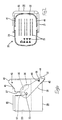
- a connector of the present embodiment is provided with a female connector housing 10, and a male connector housing 20.
- the fitting sides of these male and female housings 10 and 20 will hereafter be referred to as the anterior sides.
- the female housing 10 is formed from plastic and has a block shape. A plurality of cavities 11 are aligned therein, these forming terminal fitting insertion holes that are open to the fitting face. Female terminal fittings (not shown) can be inserted from the posterior into these cavities 11.
- a pair of follower pins 12 protrude from central portions of both lengthwise side faces of the female housing 10.
- the male housing 20 is also made from plastic. As shown in Figures 3 and 4, a main body 22 thereof has cavities 21 formed therein, and a hood 23, into which the female housing 10 fits, is formed at an anterior face side of this main body 22. A male terminal fitting (not shown) is inserted from the posterior into each cavity 21. Tabs at the tips of these male terminal fittings protrude for a specified length into the hood 23.
- the vertical dimension A and the horizontal dimension B (see Figure 3) of the main body 22 (the horizontal cross-sectional face thereof is shown here) of the male housing 20 are the same as those of the male housing 1 shown schematically in Figure 10.
- a lever 30, for performing the fitting operation is attached to the male housing 20.
- This lever 30 has a bifurcated shape whereby an operating member 32 joins tips of a pair of arms 31.
- the lever 30 is attached so as to straddle the male housing 20 from the right side (relative to Figure 1). Base ends of the arms 31 are supported by axles 33.
- the lever 30 can be pivoted between a starting position (shown in Figure 1) and an ending position (shown in Figure 6).
- the base ends of the arms 31 of the lever 30 are wide, cam grooves 35 of a specified shape being formed therein.
- the follower pins 12 of the female housing 10 fit into these cam grooves 35.
- openings 36 of the cam grooves 35 are open towards the anterior side (see Figures 1 and 3).
- Guiding grooves 37 are formed in side faces, relative to the lengthwise direction, of the hood 23. These guiding grooves 37 are formed by cutting away these side faces from opening edges towards the posterior. Guiding members 13 formed in base portions of the follower pins 12 of the female housing 10 fit into these guiding grooves 37.
- An upper supporting member 40 is formed on the right side (relative to Figure 1) of the hood 23 of the male housing 20. This upper supporting member 40 is located a little to the right relative to the position of the guiding grooves 37, and faces towards a right edge. The upper supporting member 40 rises gradually upwards from a ridge of an opening edge of the hood 23. The upper supporting member 40 protrudes only in the inserting direction of the terminal fittings of the male housing 20; it does not protrude in the widthwise direction (at a right angle to the protruding direction) beyond a side face of the male housing 20.
- a pair of upper stoppers 41 protrude along outer faces of inclined edges at both sides of the upper supporting member 40, these making contact with edges of one side of anterior ends of the arms 31 of the lever 30.
- a lower supporting member 44 is formed on the right side (relative to Figure 1) of the main body 22 of the male housing 20. This lower supporting member 44 is approximately symmetrical to the upper supporting member 40. A posterior edge of the lower supporting member 44 faces towards the right, and the lower supporting member 44 gradually retreats towards the posterior.
- the lower supporting member 44 protrudes only in the inserting direction of the terminal fittings of the male housing 20; it does not protrude in the widthwise direction (at a right angle to the protruding direction) beyond the side face of the male housing 20.
- a pair of lower stoppers 45 protrude along outer faces of inclined edges at both sides of the lower supporting member 44, these making contact with edges of the other side of the anterior ends of the arms 31 of the lever 30.
- the guiding members 13 of the female housing 10 are fitted into the guiding grooves 37 of the hood 23, and the female housing 10 is pushed, in the direction shown by the arrow in Figure 1, into the hood 23.
- the follower pins 12 of the female housing 10 then enter the openings 36 of the cam grooves 35.
- the operating member 32 is pushed so as to push the lever 30 upwards (relative to Figure 6).
- the retaining holes 38 leave the second protrusions 46 while the lever 30 is being pivoted in the anti-clockwise direction.
- the cam operation of the cam grooves 35 and the follower pins 12 gradually removes the female housing 10 from the hood 23.
- the lever 30 strikes against the upper stopper 41 (see Figure 5). This halts the lever 30, and the first protrusions 42 fit into the retaining holes 38, thereby maintaining the lever 30 in the starting position once again.
- the corresponding male and female terminal fittings are completely separated from one another, and the follower pins 12 have returned to the openings 36 of the cam grooves 35, these openings 36 opening to the anterior.
- the female housing 10 can then be pulled further, thereby separating the female and male housings 10 and 20.
- the tip of its lever is protected by the upper supporting member 40 and the lower supporting member 44 in each respective position.
- the length X of the lever 30 of the present embodiment is greater than the length x of the lever 3 of the conventional example shown in Figure 10.
- the rotative angle Y of the lever 30 is greater than the rotative angle y of the lever 3 of the conventional example, and the incline of the cam grooves 35 is more moderate than in the conventional example.
- the upper and lower supporting members 40 and 44 protrude in the direction of insertion of electric wires.
- the dimensions of the male housing 20 in the widthwise direction that is, the direction at a right angle to the direction of insertion of the electric wires
- the space in the direction of insertion of the electric wires is dead space. Consequently, the connector requires no extra space when it is positioned in place even though the supporting members 40 and 44 protrude in this direction. That is, from the viewpoint of the space required when the connector is put in position, the male housing 20 does not become larger.
- the present invention is not limited to the embodiments described above with the aid of figures. For example, the possibilities described below also lie within the technical range of the present invention. In addition, the present invention may be embodied in various other ways without deviating from the scope thereof. (1) The present invention is equally suited to a type of connector wherein the lever is provided on the female housing.
Landscapes
- Details Of Connecting Devices For Male And Female Coupling (AREA)
Abstract
Description
(1) The present invention is equally suited to a type of connector wherein the lever is provided on the female housing.
Claims (7)
- A lever-type connector having a pair of mutually engageable housings (10,20), said housings having a substantially common terminal insertion axis, one of said housings (20) having a lever (30) pivotable thereon about a pivot axis orthogonal to said insertion axis between first and second end portions, and defining a cam (35), and the other of said housings (10) having a follower (12) engageable with said cam (35), whereby said lever (30) is operable to draw together and to separate said housings (10,20), wherein said one of said housings has a profile in the direction of said insertion axis, and has supporting members (40,44) protruding in the direction of said insertion axis, and within said profile, said supporting members (40,44) providing a shield to prevent inadvertent movement of said lever from the first and second positions.
- A connector according to claim 1 wherein said lever (30) straddles said one of said housings and comprises arms (31) pivoted thereto on a common pivot axis, and a bridge (32) joining the free ends of said arms.
- A connector according to claim 2 wherein abutments (41,45) are provided on said supporting members (40,44) and for each of said arms (31).
- A connector according to claim 2 or claim 3 wherein said one of said housings (20) is substantially rectangular in the plane perpendicular to said pivot axis, said abutments (41,45) being disposed generally at two adjacent corners thereof.
- A connector according to claim 4 wherein said supporting members (40,44) comprise substantially triangular projections extending in the directions of said insertion axis, each supporting member having an upstanding wall (41,45) on the hypotenuse thereof for abutment with said lever (30).
- A connector according to any preceding claim and further including a releasable latch (38,46) to retain said lever (30) against one or other of said supporting members (40,44).
- A connector according to any preceding claim wherein the arc of movement of said lever (30) is about 90°.
Applications Claiming Priority (2)
| Application Number | Priority Date | Filing Date | Title |
|---|---|---|---|
| JP2000132311A JP4156774B2 (en) | 2000-05-01 | 2000-05-01 | Lever type connector |
| JP2000132311 | 2000-05-01 |
Publications (3)
| Publication Number | Publication Date |
|---|---|
| EP1158624A2 true EP1158624A2 (en) | 2001-11-28 |
| EP1158624A3 EP1158624A3 (en) | 2002-04-03 |
| EP1158624B1 EP1158624B1 (en) | 2003-12-10 |
Family
ID=18641041
Family Applications (1)
| Application Number | Title | Priority Date | Filing Date |
|---|---|---|---|
| EP01303736A Expired - Lifetime EP1158624B1 (en) | 2000-05-01 | 2001-04-24 | Lever-type connector |
Country Status (4)
| Country | Link |
|---|---|
| US (1) | US6488516B2 (en) |
| EP (1) | EP1158624B1 (en) |
| JP (1) | JP4156774B2 (en) |
| DE (1) | DE60101415T2 (en) |
Families Citing this family (16)
| Publication number | Priority date | Publication date | Assignee | Title |
|---|---|---|---|---|
| JP3804558B2 (en) * | 2002-03-25 | 2006-08-02 | 住友電装株式会社 | Lever type connector |
| FR2852449B1 (en) * | 2003-03-11 | 2005-04-22 | Cinch Connecteurs Sa | LOCKING LEVER FOR ELECTRICAL CONNECTOR |
| US7030600B2 (en) | 2003-11-04 | 2006-04-18 | Raytheon Company | Broadband microwave power sensor |
| US6971894B2 (en) * | 2004-03-31 | 2005-12-06 | Jst Corporation | Dual action mechanical assisted connector |
| US6971929B2 (en) * | 2004-03-31 | 2005-12-06 | Itt Manufacturing Enterprises, Inc. | Modular high density connector |
| US6899554B1 (en) | 2004-04-19 | 2005-05-31 | Jst Corporation | Dual action mechanical assisted connector |
| CN101023564A (en) * | 2004-08-13 | 2007-08-22 | Jst公司 | Lever action mechanical assist connector |
| US7267564B2 (en) * | 2005-12-01 | 2007-09-11 | Molex Incorporated | Lever type electrical connector |
| JP4941064B2 (en) * | 2007-04-09 | 2012-05-30 | 住友電装株式会社 | Lever type connector |
| JP5013336B2 (en) * | 2008-02-12 | 2012-08-29 | 矢崎総業株式会社 | LIF connector for body panel fixing |
| US7559779B1 (en) | 2008-05-14 | 2009-07-14 | Cinch Connectors, Inc. | Electrical connector |
| DE102009037201A1 (en) * | 2009-01-15 | 2010-07-22 | Bartec Gmbh | Electrical appliance unit |
| JP5622316B2 (en) * | 2010-10-18 | 2014-11-12 | 矢崎総業株式会社 | Lever type connector |
| DE102013212914A1 (en) * | 2012-08-14 | 2014-02-20 | Robert Bosch Gmbh | Electrical plug-in system |
| JP6309737B2 (en) * | 2013-10-17 | 2018-04-11 | 矢崎総業株式会社 | connector |
| JP7025464B2 (en) * | 2020-02-28 | 2022-02-24 | 矢崎総業株式会社 | connector |
Family Cites Families (19)
| Publication number | Priority date | Publication date | Assignee | Title |
|---|---|---|---|---|
| JPH03230481A (en) * | 1989-11-02 | 1991-10-14 | Maspro Denkoh Corp | Plug |
| JP2596450Y2 (en) * | 1991-10-21 | 1999-06-14 | 住友電装株式会社 | Lever temporary locking structure of lever type connector |
| JPH0536774U (en) * | 1991-10-21 | 1993-05-18 | 住友電装株式会社 | Lever type connector |
| JPH0536775U (en) * | 1991-10-21 | 1993-05-18 | 住友電装株式会社 | Lever type connector |
| GB2289171B (en) * | 1991-10-21 | 1996-03-27 | Sumitomo Wall Systems Ltd | Lever type connector |
| JP2772309B2 (en) | 1993-03-17 | 1998-07-02 | 矢崎総業株式会社 | Lever connection type connector |
| DE69426631T2 (en) * | 1993-11-05 | 2001-05-23 | Sumitomo Wiring Systems, Ltd. | LEVER CONNECTOR |
| US5586894A (en) * | 1993-11-18 | 1996-12-24 | Sumitomo Wiring Systems, Ltd. | Multiple lever connector assembly |
| JP3023868B2 (en) * | 1994-11-18 | 2000-03-21 | 矢崎総業株式会社 | Lever connection type connector |
| JP3516243B2 (en) * | 1994-11-30 | 2004-04-05 | 矢崎総業株式会社 | Connector lever locking mechanism |
| EP1079473B1 (en) * | 1995-10-24 | 2003-03-12 | Sumitomo Wiring Systems, Ltd. | Lever type connector |
| JP3243999B2 (en) * | 1996-05-24 | 2002-01-07 | 住友電装株式会社 | Lever connector |
| US5810612A (en) * | 1996-08-26 | 1998-09-22 | General Motors Corporation | Electrical connector with cam lock lever |
| JP3269793B2 (en) * | 1996-09-06 | 2002-04-02 | タイコエレクトロニクスアンプ株式会社 | Lever connector |
| US6039586A (en) * | 1996-09-06 | 2000-03-21 | The Whitaker Corporation | Lever type connector |
| JP3319387B2 (en) * | 1998-05-01 | 2002-08-26 | 住友電装株式会社 | Lever connector |
| JP3252955B2 (en) * | 1998-05-21 | 2002-02-04 | 住友電装株式会社 | Lever connector |
| JP2000036357A (en) * | 1998-07-16 | 2000-02-02 | Tokai Rika Co Ltd | Plug-in connection structure |
| JP2001035591A (en) * | 1999-07-16 | 2001-02-09 | Sumitomo Wiring Syst Ltd | Lever connector |
-
2000
- 2000-05-01 JP JP2000132311A patent/JP4156774B2/en not_active Expired - Lifetime
-
2001
- 2001-04-24 EP EP01303736A patent/EP1158624B1/en not_active Expired - Lifetime
- 2001-04-24 DE DE60101415T patent/DE60101415T2/en not_active Expired - Lifetime
- 2001-04-30 US US09/843,831 patent/US6488516B2/en not_active Expired - Lifetime
Also Published As
| Publication number | Publication date |
|---|---|
| US20010036758A1 (en) | 2001-11-01 |
| JP4156774B2 (en) | 2008-09-24 |
| JP2001313117A (en) | 2001-11-09 |
| EP1158624A3 (en) | 2002-04-03 |
| DE60101415T2 (en) | 2004-09-16 |
| US6488516B2 (en) | 2002-12-03 |
| EP1158624B1 (en) | 2003-12-10 |
| DE60101415D1 (en) | 2004-01-22 |
Similar Documents
| Publication | Publication Date | Title |
|---|---|---|
| EP1158624B1 (en) | Lever-type connector | |
| US6644992B2 (en) | Lever-type connector | |
| EP1180827B1 (en) | Lever type connector | |
| US6244910B1 (en) | Electrical box contact with stress limitation | |
| US8033856B2 (en) | Electrical connector assembly | |
| KR20020066221A (en) | Electrical connector assembly laterally deflectable latch member and CPA | |
| JP2006236926A (en) | Boot for connector and connector assembly | |
| EP0889555A2 (en) | Electrical connector assembly | |
| EP0510229A1 (en) | An electrical connector with positive latch | |
| EP1115181A1 (en) | Electrical connector | |
| US6575775B2 (en) | Connector with shorting terminal | |
| US5639270A (en) | Self-locking mating terminal structure | |
| EP1204177B1 (en) | Board mount type connector and connector board mounting structure | |
| CN107666075A (en) | Connector | |
| US6607407B2 (en) | Connector with retainer | |
| JP4082477B2 (en) | Electrical connector with terminal position assurance device | |
| JP2002289302A (en) | Electrical connector | |
| JP7427603B2 (en) | Connector position guarantee member | |
| US6533602B2 (en) | Divided connector | |
| CN114759388A (en) | Electric connector protector plate with terminal position ensuring device | |
| EP1204170B1 (en) | Electrical connector | |
| CN115411571A (en) | Connector comprising a rod and connector system provided with a connector comprising a rod | |
| US12633704B2 (en) | Connector with a CPA member | |
| JPH10289746A (en) | Female connector | |
| EP0903812A2 (en) | Plug connector having a housing with a secondary interlock |
Legal Events
| Date | Code | Title | Description |
|---|---|---|---|
| PUAI | Public reference made under article 153(3) epc to a published international application that has entered the european phase |
Free format text: ORIGINAL CODE: 0009012 |
|
| 17P | Request for examination filed |
Effective date: 20010518 |
|
| AK | Designated contracting states |
Kind code of ref document: A2 Designated state(s): AT BE CH CY DE DK ES FI FR GB GR IE IT LI LU MC NL PT SE TR Kind code of ref document: A2 Designated state(s): DE FR GB IT |
|
| AX | Request for extension of the european patent |
Free format text: AL;LT;LV;MK;RO;SI |
|
| PUAL | Search report despatched |
Free format text: ORIGINAL CODE: 0009013 |
|
| AK | Designated contracting states |
Kind code of ref document: A3 Designated state(s): AT BE CH CY DE DK ES FI FR GB GR IE IT LI LU MC NL PT SE TR |
|
| AX | Request for extension of the european patent |
Free format text: AL;LT;LV;MK;RO;SI |
|
| 17Q | First examination report despatched |
Effective date: 20020617 |
|
| AKX | Designation fees paid |
Free format text: DE FR GB IT |
|
| GRAH | Despatch of communication of intention to grant a patent |
Free format text: ORIGINAL CODE: EPIDOS IGRA |
|
| GRAS | Grant fee paid |
Free format text: ORIGINAL CODE: EPIDOSNIGR3 |
|
| GRAA | (expected) grant |
Free format text: ORIGINAL CODE: 0009210 |
|
| RIN1 | Information on inventor provided before grant (corrected) |
Inventor name: OSAWA, HIROKI,C/O SUMITOMO WIRING SYST.,LTD Inventor name: KAWASE, HAJIME,C7O SUMITOMO WIRING SYST., LTD |
|
| AK | Designated contracting states |
Kind code of ref document: B1 Designated state(s): DE FR GB IT |
|
| PG25 | Lapsed in a contracting state [announced via postgrant information from national office to epo] |
Ref country code: IT Free format text: LAPSE BECAUSE OF FAILURE TO SUBMIT A TRANSLATION OF THE DESCRIPTION OR TO PAY THE FEE WITHIN THE PRESCRIBED TIME-LIMIT;WARNING: LAPSES OF ITALIAN PATENTS WITH EFFECTIVE DATE BEFORE 2007 MAY HAVE OCCURRED AT ANY TIME BEFORE 2007. THE CORRECT EFFECTIVE DATE MAY BE DIFFERENT FROM THE ONE RECORDED. Effective date: 20031210 |
|
| REG | Reference to a national code |
Ref country code: GB Ref legal event code: FG4D |
|
| REG | Reference to a national code |
Ref country code: IE Ref legal event code: FG4D |
|
| REF | Corresponds to: |
Ref document number: 60101415 Country of ref document: DE Date of ref document: 20040122 Kind code of ref document: P |
|
| ET | Fr: translation filed | ||
| PLBE | No opposition filed within time limit |
Free format text: ORIGINAL CODE: 0009261 |
|
| STAA | Information on the status of an ep patent application or granted ep patent |
Free format text: STATUS: NO OPPOSITION FILED WITHIN TIME LIMIT |
|
| 26N | No opposition filed |
Effective date: 20040913 |
|
| REG | Reference to a national code |
Ref country code: IE Ref legal event code: MM4A |
|
| PG25 | Lapsed in a contracting state [announced via postgrant information from national office to epo] |
Ref country code: GB Free format text: LAPSE BECAUSE OF NON-PAYMENT OF DUE FEES Effective date: 20050424 |
|
| GBPC | Gb: european patent ceased through non-payment of renewal fee |
Effective date: 20050424 |
|
| REG | Reference to a national code |
Ref country code: FR Ref legal event code: PLFP Year of fee payment: 16 |
|
| REG | Reference to a national code |
Ref country code: FR Ref legal event code: PLFP Year of fee payment: 17 |
|
| REG | Reference to a national code |
Ref country code: FR Ref legal event code: PLFP Year of fee payment: 18 |
|
| REG | Reference to a national code |
Ref country code: DE Ref legal event code: R084 Ref document number: 60101415 Country of ref document: DE |
|
| PGFP | Annual fee paid to national office [announced via postgrant information from national office to epo] |
Ref country code: FR Payment date: 20200312 Year of fee payment: 20 |
|
| PGFP | Annual fee paid to national office [announced via postgrant information from national office to epo] |
Ref country code: DE Payment date: 20200415 Year of fee payment: 20 |
|
| REG | Reference to a national code |
Ref country code: DE Ref legal event code: R071 Ref document number: 60101415 Country of ref document: DE |