EP1158595A1 - High power filter, method therein and radio transmitter including the filter - Google Patents
High power filter, method therein and radio transmitter including the filter Download PDFInfo
- Publication number
- EP1158595A1 EP1158595A1 EP00850084A EP00850084A EP1158595A1 EP 1158595 A1 EP1158595 A1 EP 1158595A1 EP 00850084 A EP00850084 A EP 00850084A EP 00850084 A EP00850084 A EP 00850084A EP 1158595 A1 EP1158595 A1 EP 1158595A1
- Authority
- EP
- European Patent Office
- Prior art keywords
- filter
- chosen
- superconducting
- power
- neglible
- Prior art date
- Legal status (The legal status is an assumption and is not a legal conclusion. Google has not performed a legal analysis and makes no representation as to the accuracy of the status listed.)
- Withdrawn
Links
- 238000000034 method Methods 0.000 title claims abstract description 13
- 230000005540 biological transmission Effects 0.000 claims abstract description 15
- 230000009022 nonlinear effect Effects 0.000 claims abstract description 14
- 239000002887 superconductor Substances 0.000 claims description 13
- 239000000463 material Substances 0.000 claims description 9
- 238000012545 processing Methods 0.000 claims description 5
- 238000001914 filtration Methods 0.000 claims description 3
- 230000009021 linear effect Effects 0.000 description 5
- 239000004020 conductor Substances 0.000 description 4
- 239000010409 thin film Substances 0.000 description 4
- 238000010276 construction Methods 0.000 description 3
- 238000002307 isotope ratio mass spectrometry Methods 0.000 description 3
- 230000000737 periodic effect Effects 0.000 description 3
- 230000005520 electrodynamics Effects 0.000 description 2
- 239000010408 film Substances 0.000 description 2
- 238000012552 review Methods 0.000 description 2
- RYGMFSIKBFXOCR-UHFFFAOYSA-N Copper Chemical compound [Cu] RYGMFSIKBFXOCR-UHFFFAOYSA-N 0.000 description 1
- 238000004458 analytical method Methods 0.000 description 1
- 230000010267 cellular communication Effects 0.000 description 1
- 238000004891 communication Methods 0.000 description 1
- 229910052802 copper Inorganic materials 0.000 description 1
- 239000010949 copper Substances 0.000 description 1
- 238000003780 insertion Methods 0.000 description 1
- 230000037431 insertion Effects 0.000 description 1
- 238000005259 measurement Methods 0.000 description 1
- 230000005855 radiation Effects 0.000 description 1
- 239000000758 substrate Substances 0.000 description 1
Images
Classifications
-
- H—ELECTRICITY
- H01—ELECTRIC ELEMENTS
- H01P—WAVEGUIDES; RESONATORS, LINES, OR OTHER DEVICES OF THE WAVEGUIDE TYPE
- H01P1/00—Auxiliary devices
- H01P1/20—Frequency-selective devices, e.g. filters
- H01P1/201—Filters for transverse electromagnetic waves
- H01P1/203—Strip line filters
Definitions
- the invention is concerned with a superconducting filter, a method therein and a radio transmitter including the filter.
- a radio transmitter has to transmit desired signals of limited frequency band to an antenna.
- a radio transmitter can be considered to consist of a signal processing unit, a frequency generator and modulator and a power amplifier.
- the signal processing unit the information signal is converted to a form suitable for transmission.
- the frequency generator consisting of one or more oscillators, a carrier wave is created.
- the functions of the modulator are partly involved in those of the frequency generator. These functions vary some parameter in the output signal from the frequency generator in accordance with the information signal from the signal processing unit.
- the power amplifier increases the signal level to a suitable range.
- FDMA frequency multiple access
- TDMA time division multiple access
- CDMA code division multiple access
- WCDMA wide-band CDMA
- the size of the filters is also a factor to be taken into consideration.
- HTS Superconductor
- Transmission lines and waveguides are used to transport elctromagnetic energy at microwave frequencies from one point to another in a system without radiation of energy taking place.
- transmission lines consist of two or more parallell conductors an will guide nearly a transverse electromagnetic (TEM) wave.
- TEM transverse electromagnetic
- the common forms of transmission lines are the two-conductor line, the shielded two-conductor line, and the coaxial line.
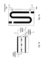
- microwave strip line which consist of a thin conducting ribbon separated from a wider ground plane by a dielectric sheet or placed between two ground planes to form a shielded structure, as shown in the example of figure 1.
- the two main advantages obtained with strip lines are the reduction in size and weight and the ability to use printed circuit techniques for the construction of the strip lines and associated components such as bends, junctions, filters, etc. a good introduction to striplines and associated components may be found in a special issue of I RE Transactions devoted entirely to this subject. See Special Issue on Microwave Strip Circuits, IRE Trans., vol. MTT-3, March, 1955.
- the stripline (figure 1a) has a center conductor 1, an upper and lower ground plane 2, 3, and a symmetric dieletric 4.
- the resonator (figure 1b) consists of a length of transmission line 5, patterned by photolitography, one half wavelength long at the fundamental frequency. Overtone resonances occur at all multiples of the fundamental frequency.
- the resonator is capacitively coupled to the external cicuit gaps at the two ends of the stripline.
- the resonator is fabricated from three separate films on three substrates clambed together in a copper package with RF connections on it. The length of the transmission line is chosen to yield a desired frequency.
- the main problem is that, with increasing input radio frequency (RF) power, the current density at the edges of, for instance, a superconducting microstripline resonator increases rapidly to such a large value that various non-linear effects, such as intermodulation distortion and harmonic generation, may appear and degrade, therefore, the performance of the filter.
- RF radio frequency
- the object of the invention is to improve the power-handling capability of superconducting filters so as to find new applications for their use.
- the method of the invention is used in a high-power superconducting filter of transmission line type. It is mainly characterized in that the peak value of the operating voltage and the characteristic impedance of the superconducting filter are chosen in such a way that the peak current is kept at a sufficiently low value so that non-linear effects induced by a high current density become neglible for a proper operation of the filter.
- the method of the invention improves the power handling capacity of superconducting filters.
- the peak value of the operating voltage V p and the characteristic impedance Z r of the superconducting filter are chosen in such a way that the peak current I p flowing in the superconductors (usually superconducting thin films) in the filter is kept to a sufficiently low value, I L (I p ⁇ I L ) depending on superconducting material and its geometry chosen, so that all non-linear effects induced otherwise by excessively high current density in superconductors become neglible for the proper (linear) operation of the filter.
- the characteristic impedance Z r of the transmission line (e.g. a microstripline) can be chosen by
- V p I L which is necessary to keep the peak current I p in the superconducting thin films at (or below) the proper level of I L to avoid possible non-linear effects caused by high current density inside the superconductor.
- I L depends on the superconductive material and its geometry used in the filter.
- the proper current value of I L introduced in this invention is an experimentally determined quantity, which depends on the superconductive material used in the filter construction and the geometric size and shape of the superconducting stripline.
- the magnetic vortex dynamic properties and the energy gap of the superconductive material play important roles in affecting the value of I L .
- the geometric size and shape of the superconducting microstripline may also affect I L by the local current density and its distribution in the superconductive material.
- the inventor of the invention has introduced a new way of thinking in designing superconducting filters.
- the invention gives the freedom to choose the parameters of the invention in a suitable way.
- Figure 1 is an example of a prior art stripline resonator
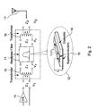
- Figure 2 is an example of a filter of the invention
- the variation in time of the current and the voltage of the filter of the invention may be described by a waveform, which varies sinusoidally in time, t.
- ⁇ is the angular frequency in rad/s.
- V p is termed the peak voltage and the term I p is termed the peak current. It is the maximum value, positive and negative, taken by the voltage over the course of one cycle.
- the mean square is relevant for the calculation of the average power dissipated in a resistor carrying the current I(t).
- P time averaged power
- the method is to let the high-power superconducting filter be operated at high-voltage and with high impedance transmission line structures so that the peak current (density) in superconductors (usually HTS thin films) of the resonator can be kept sufficiently low to avoid undesired non-linear effects caused otherwise by excessively high current density inside the superconductors.
- transformers may be used at the input and output sides of the superconducting (bandpass) filter as shown illustratevile in figure 2 in order to raise the operating voltage V r for the filter and to match the output impedance Z 1 of a power amplifier and the input impedance Z 2 of an antenna.
- Both the transformers and the filter may be made by superconductors, depending on application.
- An alternative is to use other types of impedance matching network, such as transmission line matching etc.
- FIG. 2 illustrates a part of a radio transmitter of the invention.
- a power amplifier 10 is used after the signal processing to amplify the radio signal to a power sufficient to be sent to an antenna.
- a band pass filter 11 is used to filter out undesired frequency components.
- the filter is a superconducting filter, whose peak voltage and characteristic impedance are chosen in a way so that the peak current does not exceed a certain value.
- the construction of the filter is indicated in the detailed view of reference number 12.
- the filter consists of superconductors 13 on both sides of a dielectric 14.
- the voltage V r of the filter is the voltage between the superconductors 13.
- transformer 15 may be used at the input of the filter 11 and to match the input impedance of the antenna, transformer 16 may be used at the output of the filter 11.
- the signal of desired frequency band may then be sent through the antenna 17.
Landscapes
- Physics & Mathematics (AREA)
- Electromagnetism (AREA)
- Control Of Motors That Do Not Use Commutators (AREA)
- Superconductor Devices And Manufacturing Methods Thereof (AREA)
Abstract
The invention is concerend with a method in high-power superconducting filter of
transmission line type. The peak value of the operating voltage and the
characteristic impedance of the superconducting filter are chosen in such a way
that the peak current is kept at a sufficiently low value so that non-linear effects
induced by a high current density become neglible for a proper operation of the
filter. The invention is also concerend with the high-power superconducting filter
achievd with the method and a radio transmitter in which such a filter is used.
Description
- The invention is concerned with a superconducting filter, a method therein and a radio transmitter including the filter.
- A radio transmitter has to transmit desired signals of limited frequency band to an antenna.
- As the available frequency range is restricted, for example due to international agreements and an increasing traffic, the requirements on the receivers and transmitters will also increase so that they only receive resp. generate signals of desired frequencies.
- A radio transmitter can be considered to consist of a signal processing unit, a frequency generator and modulator and a power amplifier. In the signal processing unit, the information signal is converted to a form suitable for transmission. In the frequency generator consisting of one or more oscillators, a carrier wave is created. The functions of the modulator are partly involved in those of the frequency generator. These functions vary some parameter in the output signal from the frequency generator in accordance with the information signal from the signal processing unit. Finally, the power amplifier increases the signal level to a suitable range.
- Undesired frequency components are, however, created in the transmitter of various reasons, why filtering is necessary.
- In many instances, it is important that signals from other users do not interfere. For example cellular communication systems might have two or more service providers operating on separate bands within the same geographical area. Also within a single provider's allocated frequency, it is useful to be able to handle multiple signals, as in systems using frequency multiple access (FDMA), time division multiple access (TDMA), code division multiple access (CDMA) arid wide-band CDMA (WCDMA). FDMA and TDMA users need filters to divide their allocated frequencies into multiple bands and also CDMA users might have an interest in dividing the frequency range in bands. In such cases, the narrower the bandwidth of the filter, the closer together one may place the channels.
- The size of the filters is also a factor to be taken into consideration.
- Superconductor (HTS) filters have very deep slopes and low insertion loss, while they also have a small size and low weight making them very suitable in radio frequency (RF) subsystems for high-performance radio communications systems.
- At present, the applications are limited to RF receiver filters for radio base stations while transmitter filter applications are still too difficult to be realized because of the very high power levels that these HTS structures would be required to handle in the transmitters.
- Transmission lines and waveguides are used to transport elctromagnetic energy at microwave frequencies from one point to another in a system without radiation of energy taking place. Basically, as is described in the book "Foundations for microwave engineering" by Robert E. Collin (McGraw-Hill Book Company), transmission lines consist of two or more parallell conductors an will guide nearly a transverse electromagnetic (TEM) wave. The common forms of transmission lines are the two-conductor line, the shielded two-conductor line, and the coaxial line. Another form of transmission line that has come into prominence in recent years is the microwave strip line, which consist of a thin conducting ribbon separated from a wider ground plane by a dielectric sheet or placed between two ground planes to form a shielded structure, as shown in the example of figure 1. The two main advantages obtained with strip lines are the reduction in size and weight and the ability to use printed circuit techniques for the construction of the strip lines and associated components such as bends, junctions, filters, etc. a good introduction to striplines and associated components may be found in a special issue of I RE Transactions devoted entirely to this subject. See Special Issue on Microwave Strip Circuits, IRE Trans., vol. MTT-3, March, 1955.
- An example of a superconducting filter (= stripline resonator) structure is shown in figures 1a and 1b. The stripline (figure 1a) has a center conductor 1, an upper and
lower ground plane 2, 3, and a symmetric dieletric 4. The resonator (figure 1b) consists of a length oftransmission line 5, patterned by photolitography, one half wavelength long at the fundamental frequency. Overtone resonances occur at all multiples of the fundamental frequency. The resonator is capacitively coupled to the external cicuit gaps at the two ends of the stripline. The resonator is fabricated from three separate films on three substrates clambed together in a copper package with RF connections on it. The length of the transmission line is chosen to yield a desired frequency. - The main problem is that, with increasing input radio frequency (RF) power, the current density at the edges of, for instance, a superconducting microstripline resonator increases rapidly to such a large value that various non-linear effects, such as intermodulation distortion and harmonic generation, may appear and degrade, therefore, the performance of the filter.
- The non-linear effects in superconductors are of interest both for practical applications and for the study of the fundamental properties of the materials. In a practical application, the designer must know how much power the superconductors can handle and at which power level the non-linear effects become appreciable.
- Attempts have been made to improve the power handling capability of the filters by for example studying the non-linearity dynamic and by improving material properties.
- The article "Nonlinear microwave properties of superconducting Nb microstrip resonators" by M.A. Golosovsky, 1995 The American Physical Society, Physical review B, Volume 51,
number 10 handles correlation between material properties of the films and the occurence of non-linearity. Reference to the articles "Non-linear electrodynamics of superconducting NbN and Nb thin films at microwave frequencies" by C.C. Chin et al., 1992 The American Physical Society, Physical review B, Volume 45, number 9 and "Nonlinearity of Superconducting Transmission line and Microstrip Resonator" by Orest G. vendik et al. IEEE Transactions on microwave theory and techniques, VOL. 45. No2, february 1997 are made with respect to the theory of the non-linear electrodynamics. A model for current distribution in superconductive filters can be found e.g. in "Measurements and Modeling of Linear and Nonlinear Effects in Striplines" by D.E. Oates et al. Journal of Superconductivity,Vol 5,no 4, 1992. - The earlier solutions to improve power handling capability have however not been able to improve the filters sufficiently to be able to use them in e.g. radio transmitters.
- The object of the invention is to improve the power-handling capability of superconducting filters so as to find new applications for their use.
- The method of the invention is used in a high-power superconducting filter of transmission line type. It is mainly characterized in that the peak value of the operating voltage and the characteristic impedance of the superconducting filter are chosen in such a way that the peak current is kept at a sufficiently low value so that non-linear effects induced by a high current density become neglible for a proper operation of the filter.
- The method of the invention improves the power handling capacity of superconducting filters. When for any specified (time-averaged) power P that a superconducting filter has to handle linearly, the peak value of the operating voltage Vp and the characteristic impedance Zr of the superconducting filter are chosen in such a way that the peak current Ip flowing in the superconductors (usually superconducting thin films) in the filter is kept to a sufficiently low value, IL (Ip < IL) depending on superconducting material and its geometry chosen, so that all non-linear effects induced otherwise by excessively high current density in superconductors become neglible for the proper (linear) operation of the filter. The proper value of V P (=peak value) can be chosen by using the equation Vp = 2P/IL .
- Furthermore, the characteristic impedance Zr of the transmission line (e.g. a microstripline) can be chosen by
- IL depends on the superconductive material and its geometry used in the filter. In general, the proper current value of IL introduced in this invention is an experimentally determined quantity, which depends on the superconductive material used in the filter construction and the geometric size and shape of the superconducting stripline. For instance, the magnetic vortex dynamic properties and the energy gap of the superconductive material play important roles in affecting the value of IL . The geometric size and shape of the superconducting microstripline may also affect IL by the local current density and its distribution in the superconductive material. Some detailed discussion on the subject may be found in ,for instance, recent book by S:-A. Zhou, published by John Wiley & sons, Inc., New York, 1999.
- The inventor of the invention has introduced a new way of thinking in designing superconducting filters. By releasing the usual requirement of a 50Ω impedance of the input and output port of the filter which existed for component matching reasons, the invention gives the freedom to choose the parameters of the invention in a suitable way.
- Figure 1 is an example of a prior art stripline resonator
- Figure 2 is an example of a filter of the invention
- The variation in time of the current and the voltage of the filter of the invention may be described by a waveform, which varies sinusoidally in time, t.
- Averages of waveforms give useful information as is explained in the article Electric Circuit Analysis, Principles and Applications, by K.F. Sanders, Emeritus Professor, University of Bristol published in ELECTRONIC SYSTEMS ENGINEERING SERIES, 1992.
- The average of the square of the current waveform I(t), or the means square, is denoted by <I2 > and is calculated fromwhere T = 2π/ω is the periodic time.
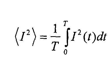
- The mean square is relevant for the calculation of the average power dissipated in a resistor carrying the current I(t). The instantaneous rate of dissipation of energy in a resistance R is
- Thus the average power is equal to
- A measure of magnitude for a wave form of which the average <I> is zero is provided by the root-mean square (RMS) value given byand by inserting the expression for I(t) we get
 as sin2x = ½(1-cos2x), we get
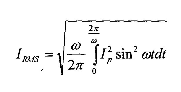 which is
- Similarly, we can get
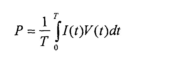
- The calculation of power bears similarities to the calculations of mean squares in that a product of time-varying functions are involved. In the case of power, these are the voltage V(t) and the current I(t)
- When the wave forms are periodic, then the power is also periodic. The average power is given bywhich by calculation gives
 and finally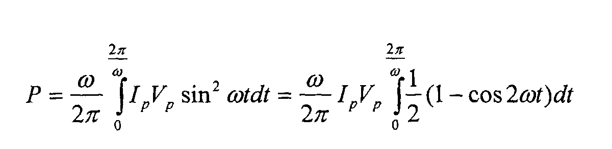
- It is supposed that there exist a superconducting microstripline type of filter with a linear power handling capability of 1W with an operating peak voltage of 10V and the characteristic impedance of 50 Ω of its microstripline (resonator). Thus, assuming a sinusoid wave form, the peak current is then 0,2 A.
- A superconducting microstripline type of filter is now designed in accordance with the invention, which is supposed to be capable of handling the time averaged power of P = 50W with sufficiently good linearity. For simplicity, we may let that the geometric sizes (cross sectional area) of the superconducting microstripline (signal line) in our filter is kept the same as that in the above example.
- Thus, since the filter in the above example is supposed to work well with sufficiently good linearity for the peak current value of 0,2 A, we may set IL = 0,2 A in our case, which implies that the peak current Ip in our case (filter) is not allowed to be higher than IL = 0,2 A. Thus, to get the linear power handling capability of P = 50 W, the operating peak voltage has to be at least
- Essentially, the method is to let the high-power superconducting filter be operated at high-voltage and with high impedance transmission line structures so that the peak current (density) in superconductors (usually HTS thin films) of the resonator can be kept sufficiently low to avoid undesired non-linear effects caused otherwise by excessively high current density inside the superconductors.
- In a practical example of the invention, transformers may be used at the input and output sides of the superconducting (bandpass) filter as shown illustratevile in figure 2 in order to raise the operating voltage Vr for the filter and to match the output impedance Z1 of a power amplifier and the input impedance Z2 of an antenna. Both the transformers and the filter may be made by superconductors, depending on application. An alternative is to use other types of impedance matching network, such as transmission line matching etc.
- Figure 2 illustrates a part of a radio transmitter of the invention. A
power amplifier 10 is used after the signal processing to amplify the radio signal to a power sufficient to be sent to an antenna. Aband pass filter 11 is used to filter out undesired frequency components. The filter is a superconducting filter, whose peak voltage and characteristic impedance are chosen in a way so that the peak current does not exceed a certain value. The construction of the filter is indicated in the detailed view ofreference number 12. The filter consists ofsuperconductors 13 on both sides of a dielectric 14. The voltage Vr of the filter is the voltage between thesuperconductors 13. To raise the voltage to asufficient level transformer 15 may be used at the input of thefilter 11 and to match the input impedance of the antenna,transformer 16 may be used at the output of thefilter 11. The signal of desired frequency band may then be sent through theantenna 17.
Claims (8)
- Method in high-power superconducting filter of transmission line type,
characterized in that the peak value of the operating voltage and the characteristic impedance of the superconducting filter are chosen in such a way that the peak current is kept at a sufficiently low value so that non-linear effects induced by a high current density become neglible for a proper operation of the filter. - Method of claim 1,characterized in that the peak value of the operating voltage V P is chosen by using the equation V P = 2P/I L , where P is the average power that the filter has to handle, and IL is the current level below which nonlinear effects of the superconductors are neglible.
- Method of claim 2, characterized in that IL depends on the superconductive material and its geometry used in the filter.
- Method of claim 1, charaterized in that the the characteristic impedance Zr of the filter (e.g. a microstripline) can be chosen by
- High-power superconducting filter of transmission line type,
characterized in that the peak value of the operating voltage and the characteristic impedance of the superconducting filter is chosen in such a way that the peak current is kept at a sufficiently low value so that non-linear effects induced by high current density become neglible for a proper operation of the filter. - Filter of claim 5, characterized in that the peak value of the operating voltage VP is chosen by using the equation VP = 2P/IL
where P is the average power that the filter has to handle, and
IL is the current level below which nonlinear effects of the superconductors are neglible. - Filter of claim 5, characterized in that the the characteristic impedance Zr of the filter (e.g. a microstripline) can be chosen by
- Radio transmitter for transmitting radio signal of desired frequencies consisting of a signal processing unit, a frequency generator/ modulator, a power amplifier and a filtering unit for filtering out undesired frequency components,
characterized in that the filter is a high-power superconducting filter, wherein the peak value of the operating voltage and the characteristic impedance of the superconducting filter is chosen in such a way that the peak current is kept at a sufficiently low value so that non-linear effects induced by a high current density become neglible for a proper operation of the filter.
Priority Applications (4)
| Application Number | Priority Date | Filing Date | Title |
|---|---|---|---|
| EP00850084A EP1158595A1 (en) | 2000-05-16 | 2000-05-16 | High power filter, method therein and radio transmitter including the filter |
| AU2001258987A AU2001258987A1 (en) | 2000-05-16 | 2001-05-15 | High power filter, method therein and radio transmitter including the filter |
| PCT/SE2001/001069 WO2001089025A1 (en) | 2000-05-16 | 2001-05-15 | High power filter, method therein and radio transmitter including the filter |
| ARP010102330A AR028580A1 (en) | 2000-05-16 | 2001-05-16 | HIGH POWER, METHOD AND RADIOTRANSMITTER FILTER INCLUDING THE FILTER |
Applications Claiming Priority (1)
| Application Number | Priority Date | Filing Date | Title |
|---|---|---|---|
| EP00850084A EP1158595A1 (en) | 2000-05-16 | 2000-05-16 | High power filter, method therein and radio transmitter including the filter |
Publications (1)
| Publication Number | Publication Date |
|---|---|
| EP1158595A1 true EP1158595A1 (en) | 2001-11-28 |
Family
ID=8175663
Family Applications (1)
| Application Number | Title | Priority Date | Filing Date |
|---|---|---|---|
| EP00850084A Withdrawn EP1158595A1 (en) | 2000-05-16 | 2000-05-16 | High power filter, method therein and radio transmitter including the filter |
Country Status (4)
| Country | Link |
|---|---|
| EP (1) | EP1158595A1 (en) |
| AR (1) | AR028580A1 (en) |
| AU (1) | AU2001258987A1 (en) |
| WO (1) | WO2001089025A1 (en) |
Family Cites Families (3)
| Publication number | Priority date | Publication date | Assignee | Title |
|---|---|---|---|---|
| EP0811257A4 (en) * | 1995-02-23 | 1998-04-29 | Superconductor Tech | Method and apparatus for increasing power handling capabilities of high temperature superconducting devices |
| US5908811A (en) * | 1997-03-03 | 1999-06-01 | Das; Satyendranath | High Tc superconducting ferroelectric tunable filters |
| JPH1168404A (en) * | 1997-08-12 | 1999-03-09 | Idotai Tsushin Sentan Gijutsu Kenkyusho:Kk | Frequency filter |
-
2000
- 2000-05-16 EP EP00850084A patent/EP1158595A1/en not_active Withdrawn
-
2001
- 2001-05-15 AU AU2001258987A patent/AU2001258987A1/en not_active Abandoned
- 2001-05-15 WO PCT/SE2001/001069 patent/WO2001089025A1/en not_active Ceased
- 2001-05-16 AR ARP010102330A patent/AR028580A1/en unknown
Non-Patent Citations (3)
| Title |
|---|
| FATHY A ET AL: "SUPERCONDUCTING NARROW BAND PASS FILTERS FOR ADVANCED MULTIPLEXERS", IEEE MTT-S INTERNATIONAL MICROWAVE SYMPOSIUM DIGEST,US,NEW YORK, IEEE, vol. -, 14 June 1993 (1993-06-14), pages 1277 - 1280, XP000481230 * |
| J TEMMYO ET AL.: "CHARACTERISTIC IMPEDANCE DESIGN CONSIDERATIONS FOR A HIGH-SPEED SUPERCONDUCTING PACKAGING SYSTEM", IEEE TRANSACTIONS ON MICROWAVE THEORY AND TECHNIQUES., vol. 33, no. 5, May 1985 (1985-05-01), IEEE INC. NEW YORK., US, pages 414 - 417, XP002147088, ISSN: 0018-9480 * |
| Z.-Y. SHEN: "HIGH-TEMPERATURE SUPERCONDUCTING MICROWAVE CIRCUITS", 1994, ARTECH HOUSE, BOSTON, XP002147089 * |
Also Published As
| Publication number | Publication date |
|---|---|
| WO2001089025A1 (en) | 2001-11-22 |
| AU2001258987A1 (en) | 2001-11-26 |
| AR028580A1 (en) | 2003-05-14 |
Similar Documents
| Publication | Publication Date | Title |
|---|---|---|
| Meier | Integrated fin-line millimeter components | |
| Grebennikov | RF and microwave transmitter design | |
| Wang et al. | A compact slow-wave microstrip branch-line coupler with high performance | |
| Liang et al. | High-power HTS microstrip filters for wireless communication | |
| CN210516948U (en) | Double-zero-point band-pass filter | |
| Mandal et al. | Reduced-length rat-race couplers | |
| Ahn et al. | Three-port 3-dB power divider terminated by different impedances and its application to MMICs | |
| Chang et al. | W-band (75-110 GHz) microstrip components | |
| Simons et al. | Channelized coplanar waveguide: discontinuities, junctions, and propagation characteristics | |
| Zhang et al. | An ultracompact superconducting bandpass filter at 40 MHz using spiral resonators and a new feedline structure | |
| Jamshidi et al. | A novel filter-based power divider for wireless communication in intelligent transportation systems | |
| Sheta et al. | A new class of miniature quadrature couplers for MIC and MMIC applications | |
| Trifunović et al. | New uniplanar balun | |
| Ma et al. | A low-loss 5GHz bandpass filter using HTS coplanar waveguide quarter-wavelength resonators | |
| Chen et al. | A microstrip dualband bandstop filter with dualband bandstop resonators | |
| Zhou et al. | HTS coplanar meander-line resonator filters with a suppressed slot-line mode | |
| Jung et al. | Microstrip ring bandpass filters with new interdigital side-coupling structure | |
| Suzuki et al. | A low-loss 5 GHz bandpass filter using HTS quarter-wavelength coplanar waveguide resonators | |
| Sonasang et al. | Improvement of microstrip band pass filter harmonic spurious suppression performance using band stop filter feed lines | |
| CN118539119B (en) | Non-reciprocal coaxial filter based on space-time modulation | |
| WO2001089025A1 (en) | High power filter, method therein and radio transmitter including the filter | |
| Lotfi et al. | Design of a Dual-Band Power Divider with Ultra-Wide Suppression Band using Triple Tapered Resonators | |
| Lee et al. | A new network model for miniaturized hairpin resonators and its applications | |
| Gillick et al. | Design analysis and fabrication of lumped‐distributed branch‐line couplers for coplanar waveguide mmics | |
| SAGAWA et al. | Bandpass filters using microstrip linear tapered transmission line resonators |
Legal Events
| Date | Code | Title | Description |
|---|---|---|---|
| PUAI | Public reference made under article 153(3) epc to a published international application that has entered the european phase |
Free format text: ORIGINAL CODE: 0009012 |
|
| AK | Designated contracting states |
Kind code of ref document: A1 Designated state(s): AT BE CH CY DE DK ES FI FR GB GR IE IT LI LU MC NL PT SE |
|
| AX | Request for extension of the european patent |
Free format text: AL;LT;LV;MK;RO;SI |
|
| AKX | Designation fees paid | ||
| REG | Reference to a national code |
Ref country code: DE Ref legal event code: 8566 |
|
| STAA | Information on the status of an ep patent application or granted ep patent |
Free format text: STATUS: THE APPLICATION IS DEEMED TO BE WITHDRAWN |
|
| 18D | Application deemed to be withdrawn |
Effective date: 20020529 |