EP1158560A1 - Inner magnetic shield and cathode-ray tube - Google Patents
Inner magnetic shield and cathode-ray tube Download PDFInfo
- Publication number
- EP1158560A1 EP1158560A1 EP00977934A EP00977934A EP1158560A1 EP 1158560 A1 EP1158560 A1 EP 1158560A1 EP 00977934 A EP00977934 A EP 00977934A EP 00977934 A EP00977934 A EP 00977934A EP 1158560 A1 EP1158560 A1 EP 1158560A1
- Authority
- EP
- European Patent Office
- Prior art keywords
- magnetic shield
- side walls
- internal magnetic
- pair
- opposing
- Prior art date
- Legal status (The legal status is an assumption and is not a legal conclusion. Google has not performed a legal analysis and makes no representation as to the accuracy of the status listed.)
- Withdrawn
Links
Images






Classifications
-
- H—ELECTRICITY
- H01—ELECTRIC ELEMENTS
- H01J—ELECTRIC DISCHARGE TUBES OR DISCHARGE LAMPS
- H01J29/00—Details of cathode-ray tubes or of electron-beam tubes of the types covered by group H01J31/00
- H01J29/02—Electrodes; Screens; Mounting, supporting, spacing or insulating thereof
-
- H—ELECTRICITY
- H01—ELECTRIC ELEMENTS
- H01J—ELECTRIC DISCHARGE TUBES OR DISCHARGE LAMPS
- H01J29/00—Details of cathode-ray tubes or of electron-beam tubes of the types covered by group H01J31/00
- H01J29/02—Electrodes; Screens; Mounting, supporting, spacing or insulating thereof
- H01J29/06—Screens for shielding; Masks interposed in the electron stream
-
- H—ELECTRICITY
- H01—ELECTRIC ELEMENTS
- H01J—ELECTRIC DISCHARGE TUBES OR DISCHARGE LAMPS
- H01J2229/00—Details of cathode ray tubes or electron beam tubes
- H01J2229/0007—Elimination of unwanted or stray electromagnetic effects
- H01J2229/003—Preventing or cancelling fields entering the enclosure
Definitions
- the present invention relates to an internal magnetic shield provided in a cathode ray tube to reduce mislanding of an electron beam due to an external magnetic field such as geomagnetism, and to a cathode ray tube including the same.
- FIG. 11 shows a conventional cathode ray tube used in television receivers, computer displays, or the like.
- An electron beam 81 released from an electron gun 80 is deflected in vertical and horizontal directions by a deflection yoke 82 to scan the entire screen, so that images are reproduced.
- the cathode ray tube is affected by an external magnetic field such as geomagnetism, the path of the electron beam 81 is distorted. Therefore, the electron beam 81 does not reach the desired position on a phosphor screen 84 formed on a front panel 83, resulting in mislanding.
- the cathode ray tube includes an internal magnetic shield 85 that provides a shield against geomagnetism or the like.
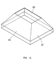
- the internal magnetic shield generally includes a pair of opposing long side walls 86, a pair of opposing short side walls 87, and an opening 88 formed in the center, or substantially V-shaped notches 89 formed on the short side walls 87 as shown in FIG. 13.
- V-shaped notches 89 are disclosed in JP 53 (1978)-15061 A, JP 7 (1995)- 192643 A, JP 5 (1993)-159713 A, or the like.
- a cathode ray tube including the internal magnetic shield without notches on the short side walls 87 or with substantially V-shaped notches
- an external magnetic field such as geomagnetism
- the amount of mislanding tends to be larger in the periphery of the screen than in the center thereof.
- mislanding occurs significantly at the corners, i.e., edges, of the screen.
- the conventional internal magnetic shields cause non-uniform mislanding throughout the screen, so that the improvement of mislanding at the corners of the screen has been necessary, particularly for a cathode ray tube that requires high definition.
- the amount of mislanding varies depending on the direction in which the cathode ray tube is oriented. To avoid this, it is preferable that the amount of mislanding due to geomagnetism in the tube-axis direction is substantially the same as that of mislanding due to geomagnetism in the horizontal direction perpendicular to the tube axis. However, it is difficult to reduce the amount of mislanding throughout the screen while achieving the balance between two mislandings by geomagnetism in different directions.
- an object of the present invention to provide an internal magnetic shield that can reduce mislanding of a deflected electron beam by an external magnetic field such as geomagnetism and prevent the displacement and unevenness of colors on the entire screen. It is another object of the present invention to provide an internal magnetic shield that easily can balance the amount of mislanding due to geomagnetism in the tube-axis direction and in the horizontal direction perpendicular to the tube axis while reducing mislanding throughout the screen. It is yet another object of the present invention to provide a cathode ray tube that can display favorable images with reduced displacement and unevenness of colors on the entire screen by including the above internal magnetic shield.
- a first internal magnetic shield for a cathode ray tube of the present invention includes a pair of opposing long side walls, a pair of opposing short side walls, and an opening enclosed by these side walls in the center. At least one pair of the long and short side walls are provided with notches having a substantially home-plate shape.
- a second internal magnetic shield for a cathode ray tube of the present invention includes a pair of opposing long side walls, a pair of opposing short side walls, and an opening enclosed by these side walls in the center. At least one pair of the long and short side walls are provided with notches. Each of the notches is formed by at least two pairs of opposing cutting edges with different orientations.
- the above first and second internal magnetic shields can reduce mislanding of a deflected electron beam by an external magnetic field such as geomagnetism and prevent the displacement and unevenness of colors on the entire screen. Moreover, they easily can balance the amount of mislanding due to geomagnetism in the tube-axis direction and in the horizontal direction perpendicular to the tube axis while reducing mislanding throughout the screen.
- a cathode ray tube of the present invention includes an envelope having a front panel and an funnel, a phosphor screen formed on the inner surface of the front panel, a color selection electrode arranged to face the phosphor screen, an electron gun placed in the funnel, and an internal magnetic shield placed between the color selection electrode and the electron gun.
- the internal magnetic shield is the magnetic shield according to the above first or second internal magnetic shield.
- the above cathode ray tube can display favorable images with reduced displacement and unevenness of colors on the entire screen, regardless of the direction in which the cathode ray tube is oriented.
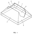
- FIG. 1 is a perspective view of an internal magnetic shield according to Embodiment 1 of the present invention.
- the internal magnetic shield of this embodiment has a pair of opposing long side walls 1 substantially in the form of a trapezoid and a pair of opposing short side walls 2 substantially in the form of a trapezoid. These side walls are joined to form a part of the surface of a quadrilateral pyramid. An opening 3 enclosed by the long and short side walls 1,2 is formed in the center of the shield.
- the internal magnetic shield is placed in a cathode ray tube with the small-width side (the upper side of FIG. 1) facing an electron gun and the large-width side (the lower side of FIG. 1) facing a phosphor screen. An electron beam passes through the opening 3.
- the short side walls are provided with notches 4, each being formed from the ends of the short side walls 2 on the electron gun side to the phosphor screen side.
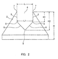
- FIG. 2 is a side view of the internal magnetic shield in FIG. 1 when viewed from the side of the short side wall 2.
- the vertical direction of FIG. 2 corresponds to the direction of the tube axis of a cathode ray tube that includes the internal magnetic shield.
- the notch 4 has a bilateral symmetry formed of a pair of opposing first cutting edges 5 and a pair of opposing second cutting edges 6.
- the first cutting edges 5 are parallel to each other.
- each of the first cutting edges 5 is parallel to the tube axis as well.
- the second cutting edges 6 intersect to form a V shape, so that a bottom 8 of the notch 4 is provided.
- the ends of the second cutting edges 6 opposite to the bottom 8 are connected to the first cutting edges 5. Since the first and second cutting edges 5, 6 are formed in different directions, each of the connections between them has a bend 9.
- the notch 4 has a substantially home-plate shape. The notch 4 thus formed is provided symmetrically on each of two opposing short side walls 2.
- an opening width of the notch 4 on the electron gun side i.e., the distance between the ends 7 of the opening
- L1 a notch width of the parallel notch portion having a constant notch width
- H1 a height of the internal magnetic shield
- H1 a depth of the parallel notch portion
- H2 a depth of the notch 4 (the length in the tube-axis direction)
- FIG. 3 shows the amount of mislanding at the corners of the screen due to geomagnetism in the tube-axis direction (hereinafter, referred to as "tube-axis geomagnetism"), when the internal magnetic shield for a cathode ray tube having a 25-inch diagonal size is used so that the notch width L1 and the depth H2 of the notch 4 are fixed, while the depth H1 of the parallel notch portion is changed.
- H1 0, the notch 4 has a V shape.
- the amount of mislanding at the corners of the screen due to the tube-axis magnetic field is decreased with increasing the depth H1 of the parallel notch portion of the notch 4.
- the reason for this is as follows: the tube-axis geomagnetism is drawn to the ends 7 of the opening and the first cutting edges 5, so that the magnetic field thus drawn cancels the force to be exerted by an external magnetic field such as geomagnetism on the electron beam traveling through its path to the phosphor screen within the internal magnetic shield.
- horizontal geomagnetism the shield effect against geomagnetism in the horizontal direction perpendicular to the tube axis
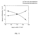
- the notch width L1 may be changed as shown in FIG. 4 to achieve the balance in the amount of mislanding due to the tube-axis geomagnetism and the horizontal geomagnetism.
- FIG. 5 shows the amount of mislanding at the corners of the screen due to the tube-axis geomagnetism and that due to the horizontal geomagnetism, when the depth H1 of the parallel notch portion and the depth H2 of the notch 4 are fixed, while the notch width L1 is changed.
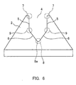
- the bottom 8 of the notch 4 may be formed in the following manner instead of simply intersecting a pair of second cutting edges 6: as shown in FIG. 6, the second cutting edges 6 are connected via a straight cutting edge 8a substantially parallel to the phosphor screen or a circular arc portion (with a rounded corner). Also, the ends 7 of the opening and the bends 9 may be formed to have a circular arc shape (with a rounded corner).
- this embodiment easily can balance the amount of mislanding due to the tube-axis geomagnetism and the horizontal geomagnetism perpendicular to the tube axis while reducing mislanding throughout the screen.
- FIG. 7 is a perspective view showing an internal magnetic shield of Embodiment 2 of the present invention.
- the internal magnetic shield of this embodiment has a pair of opposing long side walls 1 substantially in the form of a trapezoid and a pair of opposing short side walls 11 substantially in the form of a trapezoid. These side walls are joined to form a part of the surface of a quadrilateral pyramid. An opening 3 enclosed by the long and short side walls 1, 11 is formed in the center of the shield.
- the short side walls 11 are provided with notches 12, each being formed from the ends of the short side walls 11 on the electron gun side to the phosphor screen side.
- the notches 12 on the short side walls 11 of Embodiment 2 have a shape different from that of the notches 4 of Embodiment 1.
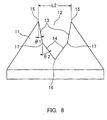
- FIG. 8 is a side view of the internal magnetic shield in FIG. 7 when viewed from the side of the short side wall 11.
- the vertical direction of FIG. 8 corresponds to the direction of the tube axis of a cathode ray tube that includes the internal magnetic shield.
- the notch 12 has a bilateral symmetry formed of a pair of opposing first cutting edges 13 and a pair of opposing second cutting edges 14.
- each of the first cutting edges 13 is inclined at an angle of ⁇ 1 with respect to the tube axis
- each of the second cutting edges 14 is inclined at an angle of ⁇ 2 with respect to the tube axis.
- the second cutting edges 14 intersect to form a V shape, so that a bottom 16 of the notch 12 is provided.
- the ends of the second cutting edges 14 opposite to the bottom 16 are connected to the first cutting edges 13. Since the first and second cutting edges 13, 14 are formed in different directions, each of the connections between them has a bend 17.
- the notch 12 thus formed is provided symmetrically on each of two opposing short side walls 11.
- the notch 12 is formed by two pairs of opposing cutting edges 13, 14 with different orientations. Therefore, like Embodiment 1, the tube-axis geomagnetism is drawn to the ends 15 of the opening and the first cutting edges 13, so that the magnetic field thus drawn cancels the force to be exerted by an external magnetic field such as geomagnetism on the electron beam traveling through its path to the phosphor screen within the internal magnetic shield. As a result, the amount of mislanding is reduced. However, when an inclination angle of ⁇ 2 is equal to that of ⁇ 1, the shield effect against the horizontal geomagnetism is reduced, causing an increase in the amount of mislanding due to the horizontal geomagnetism.
- FIG. 9 shows the amount of mislanding due to the tube-axis geomagnetism and that due to the horizontal geomagnetism, when the internal magnetic shield for a cathode ray tube having a 25-inch diagonal size is used so that the length of each of the first cutting edges 13 in the tube-axis direction is fixed, while the inclination angle ⁇ 1 is changed.
- the angle ⁇ 1 is defined to have a positive sign when a pair of first cutting edges 13 are inclined in such a direction that the distance between the bends 17 is smaller than that between the ends 15 of the opening, as shown in FIG. 8. As shown in FIG.
- the bottom 16 of the notch 12 may be formed in the following manner instead of simply intersecting a pair of second cutting edges 14: the second cutting edges 14 are connected via a straight cutting edge substantially parallel to the phosphor screen or a circular arc portion (with a rounded corner). Also, the ends 15 of the opening and the bends 17 may be formed to have a circular arc shape (with a rounded corner). Moreover, depending on the type of tube, the opening width L2 of the notch 12 on the electron gun side (i.e., the distance between the ends 15 of the opening) may be changed.
- the notch is formed by two pairs of opposing cutting edges 13, 14 with different orientations.
- the notch may be formed by three or more pairs of cutting edges with different orientations to achieve the balance of mislanding.
- this embodiment easily can balance the amount of mislanding due to the tube-axis geomagnetism and the horizontal geomagnetism perpendicular to the tube axis while reducing mislanding throughout the screen.
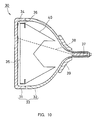
- FIG. 10 is a cross-sectional view of a color cathode ray tube 30 of the present invention taken along the tube axis in the vertical direction.
- a front panel 31 and a funnel 32 are joined to form an envelope 33.
- a substantially rectangular phosphor screen 34 is formed on the inner surface of the front panel 31.
- a color selection electrode (e.g., a shadow mask) 35 is stretched by a frame 36 so as to be spaced away from the phosphor screen 34 and opposed thereto.
- the frame 36 is held with the front panel 31 by engaging an elastic supporting body (not shown) in the form of a plate spring with a panel pin (not shown), the elastic supporting body being provided on the circumferential surface of the frame 36 and the panel pin being planted on the inner surface of the front panel 31.
- An electron gun 37 is contained in a neck portion of the funnel 32.
- An internal magnetic shield 40 is mounted on the frame 36 on the electron gun 37 side of the frame 36.
- a deflection yoke 39 that deflects an electron beam 38 from the electron gun 37 for scanning is provided on the circumferential surface of the funnel 32.
- the internal magnetic shield of Embodiment 1 or 2 is used as the internal magnetic shield 40.
- the internal magnetic shield 40 can form a diamagnetic field that cancels the force to be exerted by an external magnetic field such as geomagnetism on the electron beam 38 traveling through its path to the phosphor screen 34.
- an external magnetic field such as geomagnetism
- the force exerted on the electron beam 38 is reduced, which leads to a reduction in mislanding caused by the distortion of the electron beam path.
- this embodiment easily can balance the amount of mislanding due to the tube-axis geomagnetism and the horizontal geomagnetism perpendicular to the tube axis while reducing mislanding throughout the screen. Therefore, even if the direction in which the cathode ray tube is oriented is changed, images with reduced displacement and unevenness of colors always can be displayed.
- the short side walls have the notches.
- the present invention is not limited thereto.
- the same notches as those in the above embodiments may be formed on the long side walls instead of the short side walls, or they may be formed on both long and short side walls.
- the notches are formed by straight cutting edges.
- the present invention is not limited thereto. As long as the objects of the present invention can be achieved, the whole portion of each cutting edge or a part of it (e.g., the end of the cutting edge) may be curved slightly.
- an internal magnetic shield of the present invention there is no particular limitation on the material of an internal magnetic shield of the present invention, and a material with high permeability, e.g., iron or the like, can be used like a conventional internal magnetic shield. Also, the internal magnetic shield of the present invention can be manufactured in the same manner as that for the conventional one, such as by pressing.
Landscapes
- Electrodes For Cathode-Ray Tubes (AREA)
Abstract
Description
Claims (6)
- An internal magnetic shield for a cathode ray tube comprising:a pair of opposing long side walls;a pair of opposing short side walls; andan opening enclosed by these side walls in an center,wherein at least one pair of the long and short side walls are provided with notches having a substantially home-plate shape.
- An internal magnetic shield for a cathode ray tube comprising:a pair of opposing long side walls;a pair of opposing short side walls; andan opening enclosed by these side walls in an center,wherein at least one pair of the long and short side walls are provided with notches, and each of the notches is formed by at least two pairs of opposing cutting edges with different orientations.
- The internal magnetic shield according to claim 2, wherein one pair of the at least two pairs of opposing cutting edges are parallel to each other.
- The internal magnetic shield according to claim 2, wherein one pair of the at least two pairs of opposing cutting edges are provided so that a width of the opposing cutting edges is increased from an electron gun side to a phosphor screen side.
- The internal magnetic shield according to claim 1 or 2, wherein a straight cutting edge substantially parallel to a phosphor screen is formed at a bottom of each of the notches.
- A cathode ray tube comprising:an envelope having a front panel and a funnel;a phosphor screen formed on an inner surface of the front panel;a color selection electrode arranged to face the phosphor screen;an electron gun placed in the funnel; andan internal magnetic shield placed between the color selection electrode and the electron gun,wherein said internal magnetic shield is the magnetic shield according to claim 1 or 2.
Applications Claiming Priority (3)
| Application Number | Priority Date | Filing Date | Title |
|---|---|---|---|
| JP35293899 | 1999-12-13 | ||
| JP35293899 | 1999-12-13 | ||
| PCT/JP2000/008316 WO2001043161A1 (en) | 1999-12-13 | 2000-11-24 | Inner magnetic shield and cathode-ray tube |
Publications (2)
| Publication Number | Publication Date |
|---|---|
| EP1158560A1 true EP1158560A1 (en) | 2001-11-28 |
| EP1158560A4 EP1158560A4 (en) | 2003-01-29 |
Family
ID=18427487
Family Applications (1)
| Application Number | Title | Priority Date | Filing Date |
|---|---|---|---|
| EP00977934A Withdrawn EP1158560A4 (en) | 1999-12-13 | 2000-11-24 | INTERNAL MAGNETIC SHIELDING AND CATHODE RAY TUBE |
Country Status (6)
| Country | Link |
|---|---|
| US (1) | US6768253B1 (en) |
| EP (1) | EP1158560A4 (en) |
| JP (1) | JP2001236898A (en) |
| KR (1) | KR100436883B1 (en) |
| CN (1) | CN1346505A (en) |
| WO (1) | WO2001043161A1 (en) |
Families Citing this family (8)
| Publication number | Priority date | Publication date | Assignee | Title |
|---|---|---|---|---|
| KR20020008587A (en) * | 2000-07-24 | 2002-01-31 | 김영남 | Inner shield for a color cathode ray tube |
| KR100852688B1 (en) * | 2002-01-29 | 2008-08-19 | 삼성에스디아이 주식회사 | Magnetic shielding mechanism and cathode ray tube having the same |
| KR20040014810A (en) * | 2002-08-12 | 2004-02-18 | 삼성에스디아이 주식회사 | CRT Including Inner Magnetic Shield with Ω-shaped cutting part |
| KR100524864B1 (en) * | 2003-02-10 | 2005-10-31 | 엘지.필립스 디스플레이 주식회사 | Color cathod-ray tube |
| WO2005006382A1 (en) * | 2003-07-10 | 2005-01-20 | Matsushita Electric Industrial Co., Ltd. | Cathode ray tube |
| CN107068528B (en) * | 2016-12-28 | 2018-08-24 | 中国电子科技集团公司第十八研究所 | Electron gun protection device for electron beam focusing coil in welding vacuum chamber |
| CN109149793A (en) * | 2018-08-22 | 2019-01-04 | 上海电力学院 | Sink type magnet shielding structure and plate coil radio energy transmission system including it |
| CN116209229B (en) * | 2022-11-23 | 2026-02-24 | 上海宇航系统工程研究所 | Phase change material composite structure for radiation shielding and preparation method and application thereof |
Family Cites Families (18)
| Publication number | Priority date | Publication date | Assignee | Title |
|---|---|---|---|---|
| JPS5315061A (en) | 1976-07-27 | 1978-02-10 | Toshiba Corp | Color picture tube |
| JPS5413253A (en) * | 1977-07-01 | 1979-01-31 | Hitachi Ltd | Color receiving tube |
| US4580076A (en) * | 1982-03-31 | 1986-04-01 | Tokyo Shibaura Denki Kabushiki Kaisha | Color cathode ray tube |
| JPS6039555U (en) * | 1983-08-25 | 1985-03-19 | ソニー株式会社 | cathode ray tube |
| US4778177A (en) * | 1986-10-20 | 1988-10-18 | Taksony Joseph G | Baseball toss-up apparatus for batting practice and game play |
| JPH0216509A (en) | 1988-07-05 | 1990-01-19 | Furukawa Electric Co Ltd:The | Optical multiplexer demultiplexer |
| US5097174A (en) * | 1990-11-23 | 1992-03-17 | Thomson Consumer Electronics, Inc. | Color picture tube having an improved internal magnetic shield |
| JP3153597B2 (en) * | 1991-12-10 | 2001-04-09 | 株式会社東芝 | Color picture tube |
| KR940011935B1 (en) * | 1992-03-03 | 1994-12-27 | 삼성전관 주식회사 | Assembly structure of shadow mask frame and inner shield for color cathode ray tube |
| JPH07192643A (en) | 1993-12-28 | 1995-07-28 | Sony Corp | Internal magnetic shield |
| JP3312518B2 (en) | 1995-02-15 | 2002-08-12 | ソニー株式会社 | Internal magnetic shield, method of manufacturing the same, and cathode ray tube |
| JP3463962B2 (en) * | 1995-04-10 | 2003-11-05 | 株式会社東芝 | Color picture tube |
| JPH0927281A (en) * | 1995-07-11 | 1997-01-28 | Toshiba Corp | Color picture tube |
| JPH09147757A (en) * | 1995-11-27 | 1997-06-06 | Mitsubishi Electric Corp | Color cathode ray tube |
| JP2776356B2 (en) | 1996-01-30 | 1998-07-16 | 日本電気株式会社 | Liquid crystal display |
| KR100215774B1 (en) * | 1997-06-30 | 1999-08-16 | 구자홍 | Inner shield of cathode-ray tube |
| JPH11120930A (en) * | 1997-10-14 | 1999-04-30 | Sony Corp | Cathode ray tube |
| JP3381615B2 (en) * | 1998-03-27 | 2003-03-04 | 松下電器産業株式会社 | Color cathode ray tube |
-
2000
- 2000-11-21 JP JP2000354658A patent/JP2001236898A/en active Pending
- 2000-11-24 WO PCT/JP2000/008316 patent/WO2001043161A1/en not_active Ceased
- 2000-11-24 KR KR10-2001-7010244A patent/KR100436883B1/en not_active Expired - Fee Related
- 2000-11-24 US US09/889,840 patent/US6768253B1/en not_active Expired - Fee Related
- 2000-11-24 EP EP00977934A patent/EP1158560A4/en not_active Withdrawn
- 2000-11-24 CN CN00806031A patent/CN1346505A/en active Pending
Also Published As
| Publication number | Publication date |
|---|---|
| US6768253B1 (en) | 2004-07-27 |
| JP2001236898A (en) | 2001-08-31 |
| KR20010102099A (en) | 2001-11-15 |
| WO2001043161A1 (en) | 2001-06-14 |
| CN1346505A (en) | 2002-04-24 |
| EP1158560A4 (en) | 2003-01-29 |
| KR100436883B1 (en) | 2004-06-22 |
Similar Documents
| Publication | Publication Date | Title |
|---|---|---|
| JP3442789B2 (en) | Color picture tube with improved funnel | |
| US6768253B1 (en) | Inner magnetic shield and cathode-ray tube | |
| JP2588513B2 (en) | Color cathode ray tube | |
| US6388368B2 (en) | Color cathode ray tube having an improved internal magnetic shield | |
| US7064478B2 (en) | Color cathode-ray tube having internal magnetic screening | |
| JP3381615B2 (en) | Color cathode ray tube | |
| JPH06310047A (en) | Cathode-ray tube | |
| JP2582158Y2 (en) | Color cathode ray tube | |
| KR100634732B1 (en) | Frame of color cathode ray tube | |
| US6979943B2 (en) | Cathode ray tube having magnetic shield with a bent portion | |
| KR100451802B1 (en) | Panel for crt | |
| JP2886614B2 (en) | Color cathode ray tube | |
| JP2000311620A (en) | Internal magnetic shield and color cathode-ray tube | |
| JP3978220B2 (en) | Cathode ray tube | |
| JP3785937B2 (en) | Picture tube device | |
| JP2002313248A (en) | Internal magnetic shield and cathode ray tube | |
| JP2000030622A (en) | Color cathode ray tube | |
| JPH08171866A (en) | Cathode-ray tube | |
| JPH03187131A (en) | Color picture tube | |
| JP2003162967A (en) | Internal magnetic shield for color cathode ray tube and color cathode ray tube with internal magnetic shield | |
| JP2001185042A (en) | Cathode ray tube | |
| US20040032196A1 (en) | Cathode ray tube | |
| JPH07105863A (en) | Color picture tube device | |
| JP2002075235A (en) | Cathode ray tube | |
| JP2003007219A (en) | Color cathode ray tube |
Legal Events
| Date | Code | Title | Description |
|---|---|---|---|
| PUAI | Public reference made under article 153(3) epc to a published international application that has entered the european phase |
Free format text: ORIGINAL CODE: 0009012 |
|
| 17P | Request for examination filed |
Effective date: 20010802 |
|
| AK | Designated contracting states |
Kind code of ref document: A1 Designated state(s): AT BE CH CY DE DK ES FI FR GB GR IE IT LI LU MC NL PT SE TR |
|
| AX | Request for extension of the european patent |
Free format text: AL;LT;LV;MK;RO;SI |
|
| A4 | Supplementary search report drawn up and despatched |
Effective date: 20021216 |
|
| RIC1 | Information provided on ipc code assigned before grant |
Ipc: 7H 01J 29/02 A Ipc: 7H 01J 29/06 B |
|
| RBV | Designated contracting states (corrected) |
Designated state(s): DE FR GB IT NL |
|
| 17Q | First examination report despatched |
Effective date: 20050112 |
|
| STAA | Information on the status of an ep patent application or granted ep patent |
Free format text: STATUS: THE APPLICATION IS DEEMED TO BE WITHDRAWN |
|
| RAP1 | Party data changed (applicant data changed or rights of an application transferred) |
Owner name: PANASONIC CORPORATION |
|
| 18D | Application deemed to be withdrawn |
Effective date: 20080607 |