EP1158520A2 - Positioning actuator with lower inductance voice coil motor - Google Patents
Positioning actuator with lower inductance voice coil motor Download PDFInfo
- Publication number
- EP1158520A2 EP1158520A2 EP20010102683 EP01102683A EP1158520A2 EP 1158520 A2 EP1158520 A2 EP 1158520A2 EP 20010102683 EP20010102683 EP 20010102683 EP 01102683 A EP01102683 A EP 01102683A EP 1158520 A2 EP1158520 A2 EP 1158520A2
- Authority
- EP
- European Patent Office
- Prior art keywords
- carriage
- coil
- post
- guide rail
- motor
- Prior art date
- Legal status (The legal status is an assumption and is not a legal conclusion. Google has not performed a legal analysis and makes no representation as to the accuracy of the status listed.)
- Withdrawn
Links
- 239000004020 conductor Substances 0.000 claims abstract description 10
- BQCADISMDOOEFD-UHFFFAOYSA-N Silver Chemical compound [Ag] BQCADISMDOOEFD-UHFFFAOYSA-N 0.000 claims abstract description 7
- 239000002184 metal Substances 0.000 claims abstract description 7
- 229910052751 metal Inorganic materials 0.000 claims abstract description 7
- 229910052709 silver Inorganic materials 0.000 claims abstract description 7
- 239000004332 silver Substances 0.000 claims abstract description 7
- RYGMFSIKBFXOCR-UHFFFAOYSA-N Copper Chemical compound [Cu] RYGMFSIKBFXOCR-UHFFFAOYSA-N 0.000 claims abstract description 6
- 229910052802 copper Inorganic materials 0.000 claims abstract description 6
- 239000010949 copper Substances 0.000 claims abstract description 6
- PCHJSUWPFVWCPO-UHFFFAOYSA-N gold Chemical compound [Au] PCHJSUWPFVWCPO-UHFFFAOYSA-N 0.000 claims abstract description 5
- 229910052737 gold Inorganic materials 0.000 claims abstract description 5
- 239000010931 gold Substances 0.000 claims abstract description 5
- 238000004804 winding Methods 0.000 claims abstract description 5
- 239000000463 material Substances 0.000 claims description 7
- 230000004907 flux Effects 0.000 description 6
- 230000036316 preload Effects 0.000 description 3
- 239000000853 adhesive Substances 0.000 description 2
- 230000001070 adhesive effect Effects 0.000 description 2
- 238000013016 damping Methods 0.000 description 2
- 230000005484 gravity Effects 0.000 description 2
- 230000007246 mechanism Effects 0.000 description 2
- 239000012811 non-conductive material Substances 0.000 description 2
- 230000009467 reduction Effects 0.000 description 2
- 239000004593 Epoxy Substances 0.000 description 1
- 229910000831 Steel Inorganic materials 0.000 description 1
- 230000001133 acceleration Effects 0.000 description 1
- 230000000712 assembly Effects 0.000 description 1
- 238000000429 assembly Methods 0.000 description 1
- 239000003292 glue Substances 0.000 description 1
- 230000004048 modification Effects 0.000 description 1
- 238000012986 modification Methods 0.000 description 1
- 238000007747 plating Methods 0.000 description 1
- 230000007480 spreading Effects 0.000 description 1
- 239000010959 steel Substances 0.000 description 1
Images




Classifications
-
- G—PHYSICS
- G11—INFORMATION STORAGE
- G11B—INFORMATION STORAGE BASED ON RELATIVE MOVEMENT BETWEEN RECORD CARRIER AND TRANSDUCER
- G11B21/00—Head arrangements not specific to the method of recording or reproducing
- G11B21/02—Driving or moving of heads
- G11B21/022—Programmed access in sequence to indexed parts of operating record carriers
- G11B21/027—Programmed access in sequence to indexed parts of operating record carriers of tapes
Definitions
- the present invention relates generally to tape drive and other head positioning actuators and, more particularly, to a head positioning actuator using a lower inductance voice coil motor.
- Information is recorded on and read from a moving magnetic tape with a magnetic read/write head positioned next to the tape.
- the magnetic "head" may be a single head or, as is common, a series of read/write head elements stacked individually and/or in pairs within the head unit. Data is recorded in tracks on the tape by moving the tape lengthwise past the head.
- the head elements are selectively activated by electric currents representing the information to be recorded on the tape.
- the information is read from the tape by moving the tape longitudinally past the head elements so that magnetic flux patterns on the tape create electric signals in the head elements. These signals represent the information stored on the tape.
- Data is recorded on and read from each of the parallel tracks on the tape by positioning the head elements at different locations across the tape. That is, head elements are moved from track to track as necessary to either record or read the desired information. Movement of the magnetic head is controlled by an actuator operatively coupled to some type of servo control circuitry. Tape drive head positioning actuators often include a lead screw driven by a stepper motor, a voice coil motor, or a combination of both. The carriage that supports the head is driven by the actuator along a path perpendicular to the direction that the tape travels. The head elements are positioned as close to the center of a track as possible based upon the servo information recorded on the tape.
- Hewlett Packard Company has developed a new servo controlled head positioning actuator designed to move the head rapidly to keep the read/write elements correctly positioned on the tape tracks even as the tape wanders back and forth within the tape guiding system.
- This head positioning actuator which is described in detail below, uses a linear actuator driven by a voice coil motor.
- One factor that may limit the actuator's ability to move the head rapidly to keep the head elements positioned correctly over the tape tracks is the delivery of current to the coil in the voice coil motor. Lowering the inductance of the coil allows current to flow more quickly into the coil which, in turn, allows the voice coil motor to drive the actuator and move the head as rapidly as possible to the correct position.
- a copper tube around the center core of the voice coil motor in disc drive actuators is sometimes used as a shorted turn to lower the inductance of the motor and thereby reduce the time it takes to move the head to the correct position over the disc.
- This type of shorted turn is very difficult to implement in Hewlett Packard's new tape drive head positioning actuator because the primary guide rail in this new design is usually solidly attached to and extends along the center core of the voice coil motor. Hence, it is difficult to add a conductive tube around the center core of the voice coil motor.
- the present invention is directed to a positioning actuator that includes a linear actuator driven by a voice coil motor.
- the center core of the voice coil motor is covered with a highly conductive material that provides a shorted turn to lower the inductance of the motor.
- the actuator of the present invention includes an annular coil of electrically conductive windings, a magnet surrounding at least a part of the coil, a metal post extending axially through the inside of the coil, a guide rail extending axially through the inside of the coil along the post, and a carriage moveably coupled to the guide rail for travel thereon. At least part of the post is covered with highly electrically conductive material such as copper, silver or gold.
- a magnetic tape 12 is wound on a single supply spool 14 and tape cartridge 16.
- Tape cartridge 16 is inserted into tape drive 10 for read and write operations.
- Tape 12 passes around tape guide 17, over a magnetic read/write head 18, around tape guide 19 to take up spool 20.
- Head 18 is mounted to a head carriage and actuator assembly 22 that includes a variety of operational features related to head 18. Head carriage and actuator assembly 22 is also referred to for convenience as actuator 22.
- Magnetic head 18 engages tape 12 as tape 12 moves across the face of head 18 to record data on tape 12 and to read data from tape 12.
- Fig. 2 is a perspective view of the actuator 22.
- Figs. 3, 4 and 5 are elevation and plan views of actuator 22.
- the operative components of actuator 22 are best seen in Figs. 3-5.
- head 18 is carried by a moveable carriage 24.
- Carriage 24 moves up and down along a primary guide rail 26 and a secondary guide rail 28 at the urging of voice coil motor 30.
- Head 18, which is carried by carriage 24, therefore, also moves up and down in a direction perpendicular to the direction of tape travel as desired to properly position head 18 for reading and writing operations.
- Figs. 3A and 3B show carriage 24 and head 18 in different positions along the guide rails.
- Voice coil motor 30 includes a coil 32 and magnets 34. Magnets 34 are attached to the inside of sidewalls 54 of actuator base 50. Top flux plate 36 fits on top of sidewalls 54 of base 50. Actuator base 50 is secured to the frame or another stable component of tape drive 10. Coil 32 is mounted to carriage 24.
- carriage 24 includes a front portion 38, a back portion 40 and truncated ring shaped center portions 42A and 42B that join the front and back portions 38, 40.
- Center portions 42A and 42B are positioned inside a circumferential perimeter defined by magnets 34.
- the ring shaped center portions 42A and 42B are spaced apart a distance equal to or slightly greater than the height (the axial dimension) of coil 32.
- Coil 32 is sandwiched between and firmly attached to ring shaped center portions 42B and 42C in carriage 24. Coil 32 is exposed at cavities 44 formed on each side of carriage 24 between ring shaped center portions 42A and 42B.
- a post 46 extends vertically through the center portion of coil 32.
- post 46 is the upright core portion of actuator base 50.
- Primary guide rail 26 extends up along a V-shaped trough 48 formed in the front side of core 42.
- Secondary guide rail 28 is positioned at the back of carriage 24 just outside coil 32.
- Head 18 is mounted to front piece 38 of carriage 24.
- a position sensor 52 that reads the vertical position of carriage 24 may be mounted between back piece 40 and actuator base 50.
- Carriage 24 travels along primary guide rail 26 on two pairs of bearings 56A and 56B mounted in the front piece 38 of carriage 24.
- Carriage 24 travels along secondary guide rail 28 on one pair of bearings 58 mounted in the back piece 40 of carriage 24.
- bearings 56A are mounted at the top of carriage 24
- bearings 56B are mounted at the bottom 62 of carriage 24
- bearings 58 are mounted at the middle of carriage 24.
- bearings 56A and 56B control the position of carriage 24 in the azimuth direction, indicated by arrow A in Fig. 5, and the zenith direction, indicated by arrow Z in Fig. 3A.
- Bearings 58 control the position of carriage 24 in the yaw direction, indicated by arrow Y in Fig. 4.
- FIG. 7 One type of bearing preload mechanism is shown in Fig. 7. Referring to Fig. 7, one or both of the secondary rail bearings 58 are spring loaded against secondary guide rail 28.
- a spring 64 which supports bearing 58, extends between back portion 40 of carriage 24 and bearing shaft 59. Spring 64 generates a spring force F that pushes bearing 58 against secondary guide rail 28 and pulls carriage 24 rearward. The rearward pull of carriage 24 urges the primary guide rail bearings 56 against primary guide 26.
- actuator 22 positions head 18 relative to tape 12 according to positional information recorded on tape 12. It may be desirable, and in some cases necessary, to make one or all of top flux plate 36, post 46 and actuator base 50 from a soft magnetic steel to carry the magnetic flux 66 generated by magnets 34 through the space occupied by coil 32, as shown in Fig. 8.
- a servo control signal is generated from the positional information on tape 12 through servo control circuitry (not shown) and delivered as an electrical current to voice coil 32.
- the presence of current in coil 32 in the magnetic field generated by magnets 34 creates a vertical force on coil 32 and, correspondingly, on carriage 24. This vertical force moves carriage 24 and head 18 up or down as necessary to properly position head 18 relative to tape 12.
- the position of primary guide rail 26 inside coil 32 and the position of bearings 56A and 56B above and below coil 32 minimizes the amount of mass needed at the back of carriage 24 to place the center of gravity of carriage 24 at the same location as the center of force exerted by voice coil motor 30. Positioning the center of gravity of carriage 24 at the same location as the center of force of voice coil motor 30 reduces the amplitude of the carriage rocking modes. So, by locating primary guide rail 26 inside coil 32, the overall mass of carriage 24 can be reduced. A more compact design can also be achieved by positioning coil 32 between primary guide rail bearings 56A and 56B. This configuration allows the positioning of head 18 closer to the center of force of voice coil motor 30 to further reduce the size and mass of carriage 24.
- fastening primary guide rail 26 to post 46 eliminates the need to provide other support for primary guide rail 26, particularly at the ends of the primary guide rail.
- the added stiffness allows higher resonant frequencies of the rocking modes of carriage 24 and, hence, a higher band width for the servo control system.
- carriage 24, or at least one of the center portions 42A and 42B, are made of conductive material, then the carriage will form an electrically conductive loop in the magnetic flux of voice coil motor 30. The movement of carriage 24 as it is driven by motor 30, therefore, will generate an electrical current through this conductive loop. The current in carriage 24 generates a damping force that acts on carriage 24 in a direction opposite the direction of travel and is proportional to the velocity of the carriage. This damping force can be avoided by making carriage 24, or at least the center portions 42A and 42B, from a non-conductive material or by forming a non-conductive break in the otherwise conductive carriage loop. Fig. 6C shows such a non-conductive break in carriage 24. Referring to Fig.
- a strip 41 of adhesive material fills a break made in carriage 24 near one of the junctions of back portions 40 and center portions 42A and 42B.
- any electrically non-conductive material may be used, an epoxy or other strong adhesive is preferred to help maintain the structural integrity of carriage 24.
- Fig. 9 which is perspective view of the interior of actuator 22, post 46 that forms the center core of actuator 22 is covered with a material that is highly electrically conductive.
- This conductive covering is designated by reference number 68.
- "Highly" electrically conductive in this context means more conductive than the material forming post/core 46. Copper, silver, gold and similarly conductive materials are the most desirable.
- Conductive covering 68 on center core 46 provides a low resistance path, commonly called a shorted turn, through which electrical currents induced in the core can flow more rapidly. The shorted turn lowers the inductance of the actuator's voice coil motor 30. Lowering the inductance of motor 30 allows more current to flow more quickly into coil 32 for a set voltage to produce faster acceleration of head carriage 24 and correspondingly, faster positioning of head 18.
- covering 68 is to plate the conductive material on to center core 46. Primary guide rail 26 can then be fastened to core 46 as described above.
- the thickness of covering 68 will vary depending on the type of covering material, the electrical and magnetic characteristics of core 46 and the other components of actuator 22, as well as the inductance desired for coil 32, it is expected that copper, silver or gold coverings up to about 0.4mm thick will provide a desirable level of inductance reduction in voice coil motor driven actuators such as the one shown in the Figures. It has been observed that a silver plated covering 68 0.3mm thick reduces the inductance of coil 32 by 50%.
- the inductance of coil 32 drops sharply as a very thin (less than 0.05mm) covering is applied with the reduction curve tailing off to become nearly flat once the thickness of covering 68 reaches 0.4 to 0.5mm. While it is expected that covering 68 will be formed to a uniform thickness over substantially all of core 46, varying degrees of coverage are possible alone or in combination with varying the thickness of covering 68 as necessary or desirable to achieve the required shorted turn.
- Bearings as used herein means any suitable object, structure or surface that moveably supports the carriage for travel along the rails. Suitable bearings may include, for example, ball bearings, roller bearings, Gothic arch bearings, journal bearings, bushings and the like.
- the invention may be embodied in other carriage and actuator assemblies, structures and designs.
- the invention could be incorporated in many different types of servo positioned actuators that use a voice coil motor.
- the voice coil motor might be configured so that the magnets are secured to the head carriage and the coil remains stationary. And, the coil need not be annular. A square or rectangular coil may be appropriate in some applications.
- the post and the primary guide rail could be formed as an integral unit, rather the discrete components described above.
- the sidewalls of the actuator base might be formed integral to the base foundation, as shown in Figs. 2, 5 and 6, or the sidewalls might be formed integral with the top plate and separate from the base. Therefore, it is to be understood that these and other variations of and modifications to the embodiments shown and described may be made without departing from the spirit and scope of the invention as defined in following claims.
Landscapes
- Reciprocating, Oscillating Or Vibrating Motors (AREA)
- Moving Of Heads (AREA)
- Adjustment Of The Magnetic Head Position Track Following On Tapes (AREA)
- Linear Motors (AREA)
Abstract
A positioning actuator that includes a linear actuator driven by a
voice coil motor (30). The center core (46) of the voice coil motor (30) is
covered with a highly conductive material (68) that provides a shorted turn to
lower the inductance of the motor (30). The actuator includes an annular coil
(32) of electrically conductive windings, a magnet (34) surrounding at least a
part of the coil (32), a metal post (46) extending axially through the inside of
the coil (32), a guide rail (26 or 28) extending axially through the inside of the
coil (32) along the post (46), and a carriage (24) moveably coupled to the guide
rail (26 or 28) for travel thereon. At least part of the post (46) is covered with
highly electrically conductive material (68) such as copper, silver or gold.
Description
- The present invention relates generally to tape drive and other head positioning actuators and, more particularly, to a head positioning actuator using a lower inductance voice coil motor.
- Information is recorded on and read from a moving magnetic tape with a magnetic read/write head positioned next to the tape. The magnetic "head" may be a single head or, as is common, a series of read/write head elements stacked individually and/or in pairs within the head unit. Data is recorded in tracks on the tape by moving the tape lengthwise past the head. The head elements are selectively activated by electric currents representing the information to be recorded on the tape. The information is read from the tape by moving the tape longitudinally past the head elements so that magnetic flux patterns on the tape create electric signals in the head elements. These signals represent the information stored on the tape.
- Data is recorded on and read from each of the parallel tracks on the tape by positioning the head elements at different locations across the tape. That is, head elements are moved from track to track as necessary to either record or read the desired information. Movement of the magnetic head is controlled by an actuator operatively coupled to some type of servo control circuitry. Tape drive head positioning actuators often include a lead screw driven by a stepper motor, a voice coil motor, or a combination of both. The carriage that supports the head is driven by the actuator along a path perpendicular to the direction that the tape travels. The head elements are positioned as close to the center of a track as possible based upon the servo information recorded on the tape.
- Hewlett Packard Company has developed a new servo controlled head positioning actuator designed to move the head rapidly to keep the read/write elements correctly positioned on the tape tracks even as the tape wanders back and forth within the tape guiding system. This head positioning actuator, which is described in detail below, uses a linear actuator driven by a voice coil motor. One factor that may limit the actuator's ability to move the head rapidly to keep the head elements positioned correctly over the tape tracks is the delivery of current to the coil in the voice coil motor. Lowering the inductance of the coil allows current to flow more quickly into the coil which, in turn, allows the voice coil motor to drive the actuator and move the head as rapidly as possible to the correct position.
- A copper tube around the center core of the voice coil motor in disc drive actuators is sometimes used as a shorted turn to lower the inductance of the motor and thereby reduce the time it takes to move the head to the correct position over the disc. This type of shorted turn is very difficult to implement in Hewlett Packard's new tape drive head positioning actuator because the primary guide rail in this new design is usually solidly attached to and extends along the center core of the voice coil motor. Hence, it is difficult to add a conductive tube around the center core of the voice coil motor.
- Accordingly, the present invention is directed to a positioning actuator that includes a linear actuator driven by a voice coil motor. The center core of the voice coil motor is covered with a highly conductive material that provides a shorted turn to lower the inductance of the motor. The actuator of the present invention includes an annular coil of electrically conductive windings, a magnet surrounding at least a part of the coil, a metal post extending axially through the inside of the coil, a guide rail extending axially through the inside of the coil along the post, and a carriage moveably coupled to the guide rail for travel thereon. At least part of the post is covered with highly electrically conductive material such as copper, silver or gold.
-
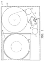
- Fig. 1 is a top down plan view of a tape drive incorporating a head positioning actuator constructed according to one embodiment of the present invention.
- Fig. 2 is a perspective view of the moveable carriage and head positioning actuator of Fig. 1.
- Figs. 3A and 3B are side elevation and partial section views of the moveable carriage and head positioning actuator of Figs. 1 and 2 in different positions along the guide rails.
- Fig. 4 is a top down plan and partial section view of the moveable carriage and head positioning actuator taken along the line 4-4 in Fig. 3A.
- Fig. 5 is a front elevation and partial cut-away view of the moveable carriage and head positioning actuator as viewed along the line 5-5 in Fig. 4.
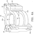
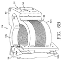
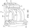
- Figs. 6A, 6B and 6C are detail perspective views of the head carriage. Fig. 6A illustrates the carriage without the coil. Fig. 6B illustrates the carriage with the coil installed in the carriage. Fig. 6C illustrates a carriage in which a non-conductive break is made between the center portions of the carriage and the back portion of the carriage.
- Fig. 7 is a detail side elevation view of the back portion of the carriage showing one type of bearing preload mechanism.
- Fig. 8 is a representational side view of the actuator showing the magnetic flux in the voice coil motor.
- Figs. 9 and 10 are detail perspective views of the center core of the voice coil motor showing the conductive covering on the core.
-
- Referring first to Fig.1, a
magnetic tape 12 is wound on asingle supply spool 14 andtape cartridge 16.Tape cartridge 16 is inserted intotape drive 10 for read and write operations. Tape 12 passes aroundtape guide 17, over a magnetic read/writehead 18, aroundtape guide 19 to take upspool 20.Head 18 is mounted to a head carriage andactuator assembly 22 that includes a variety of operational features related tohead 18. Head carriage andactuator assembly 22 is also referred to for convenience asactuator 22.Magnetic head 18 engagestape 12 astape 12 moves across the face ofhead 18 to record data ontape 12 and to read data fromtape 12. - Fig. 2 is a perspective view of the
actuator 22. Figs. 3, 4 and 5 are elevation and plan views ofactuator 22. The operative components ofactuator 22 are best seen in Figs. 3-5. Referring to Figs. 2-5,head 18 is carried by amoveable carriage 24. Carriage 24 moves up and down along aprimary guide rail 26 and asecondary guide rail 28 at the urging ofvoice coil motor 30.Head 18, which is carried bycarriage 24, therefore, also moves up and down in a direction perpendicular to the direction of tape travel as desired to properly positionhead 18 for reading and writing operations. Figs. 3A and 3B showcarriage 24 and head 18 in different positions along the guide rails. -
Voice coil motor 30 includes acoil 32 andmagnets 34.Magnets 34 are attached to the inside ofsidewalls 54 ofactuator base 50.Top flux plate 36 fits on top ofsidewalls 54 ofbase 50.Actuator base 50 is secured to the frame or another stable component oftape drive 10.Coil 32 is mounted tocarriage 24. - The details of
carriage 24 are best seen in Figs. 6A and 6B. Fig. 6A is a perspective view ofcarriage 24 withoutcoil 32. Fig. 6B is a perspective view ofcarriage 24 withcoil 32 installed. Referring to Figs. 6A and 6B,carriage 24 includes afront portion 38, aback portion 40 and truncated ring shaped center portions 42A and 42B that join the front andback portions magnets 34. The ring shaped center portions 42A and 42B are spaced apart a distance equal to or slightly greater than the height (the axial dimension) ofcoil 32.Coil 32 is sandwiched between and firmly attached to ring shaped center portions 42B and 42C incarriage 24.Coil 32 is exposed atcavities 44 formed on each side ofcarriage 24 between ring shaped center portions 42A and 42B. - Referring again to Figs. 2-5, a
post 46 extends vertically through the center portion ofcoil 32. In the embodiment of the invention shown in the drawings, post 46 is the upright core portion ofactuator base 50.Primary guide rail 26 extends up along a V-shapedtrough 48 formed in the front side ofcore 42.Secondary guide rail 28 is positioned at the back ofcarriage 24 just outsidecoil 32.Head 18 is mounted tofront piece 38 ofcarriage 24. If necessary or desirable, aposition sensor 52 that reads the vertical position ofcarriage 24 may be mounted betweenback piece 40 andactuator base 50.Carriage 24 travels alongprimary guide rail 26 on two pairs of bearings 56A and 56B mounted in thefront piece 38 ofcarriage 24.Carriage 24 travels alongsecondary guide rail 28 on one pair ofbearings 58 mounted in theback piece 40 ofcarriage 24. Preferably, bearings 56A are mounted at the top ofcarriage 24, bearings 56B are mounted at the bottom 62 ofcarriage 24, andbearings 58 are mounted at the middle ofcarriage 24. In this configuration, bearings 56A and 56B control the position ofcarriage 24 in the azimuth direction, indicated by arrow A in Fig. 5, and the zenith direction, indicated by arrow Z in Fig. 3A.Bearings 58 control the position ofcarriage 24 in the yaw direction, indicated by arrow Y in Fig. 4. - It may be desirable to preload one or both
bearings 58 againstsecondary rail 28 to maintain contact of all of the bearings against the rails. One type of bearing preload mechanism is shown in Fig. 7. Referring to Fig. 7, one or both of thesecondary rail bearings 58 are spring loaded againstsecondary guide rail 28. Aspring 64, which supportsbearing 58, extends betweenback portion 40 ofcarriage 24 and bearingshaft 59.Spring 64 generates a spring force F that pushes bearing 58 againstsecondary guide rail 28 and pullscarriage 24 rearward. The rearward pull ofcarriage 24 urges the primary guide rail bearings 56 againstprimary guide 26. - In operation, actuator 22 positions head 18 relative to tape 12 according to positional information recorded on
tape 12. It may be desirable, and in some cases necessary, to make one or all oftop flux plate 36,post 46 andactuator base 50 from a soft magnetic steel to carry themagnetic flux 66 generated bymagnets 34 through the space occupied bycoil 32, as shown in Fig. 8. A servo control signal is generated from the positional information ontape 12 through servo control circuitry (not shown) and delivered as an electrical current tovoice coil 32. The presence of current incoil 32 in the magnetic field generated bymagnets 34 creates a vertical force oncoil 32 and, correspondingly, oncarriage 24. This vertical force movescarriage 24 andhead 18 up or down as necessary to properly positionhead 18 relative to tape 12. - The position of
primary guide rail 26 insidecoil 32 and the position of bearings 56A and 56B above and belowcoil 32 minimizes the amount of mass needed at the back ofcarriage 24 to place the center of gravity ofcarriage 24 at the same location as the center of force exerted byvoice coil motor 30. Positioning the center of gravity ofcarriage 24 at the same location as the center of force ofvoice coil motor 30 reduces the amplitude of the carriage rocking modes. So, by locatingprimary guide rail 26 insidecoil 32, the overall mass ofcarriage 24 can be reduced. A more compact design can also be achieved by positioningcoil 32 between primary guide rail bearings 56A and 56B. This configuration allows the positioning ofhead 18 closer to the center of force ofvoice coil motor 30 to further reduce the size and mass ofcarriage 24. - It is desirable to glue or otherwise fasten
primary guide rail 26 to post 46 to increase the stiffness ofprimary guide rail 26. In addition, fasteningprimary guide rail 26 to post 46 eliminates the need to provide other support forprimary guide rail 26, particularly at the ends of the primary guide rail. The added stiffness allows higher resonant frequencies of the rocking modes ofcarriage 24 and, hence, a higher band width for the servo control system. It is also desirable to separate upper guide bearings 56A from lower guide bearings 56B as much as possible without exceeding the vertical height limitations ofactuator 22 andtape drive 10. Since the lowest stiffness member in determining the carriage rocking frequencies is the bearings, spreading the bearings as far apart as possible increases the effective stiffness of the carriage guide system. So, by maximizing the spacing between bearings 56A and 56B, the resonant frequency of the carriage rocking modes can be made as high as possible for a given stiffness of bearings. - If
carriage 24, or at least one of the center portions 42A and 42B, are made of conductive material, then the carriage will form an electrically conductive loop in the magnetic flux ofvoice coil motor 30. The movement ofcarriage 24 as it is driven bymotor 30, therefore, will generate an electrical current through this conductive loop. The current incarriage 24 generates a damping force that acts oncarriage 24 in a direction opposite the direction of travel and is proportional to the velocity of the carriage. This damping force can be avoided by makingcarriage 24, or at least the center portions 42A and 42B, from a non-conductive material or by forming a non-conductive break in the otherwise conductive carriage loop. Fig. 6C shows such a non-conductive break incarriage 24. Referring to Fig. 6C, astrip 41 of adhesive material fills a break made incarriage 24 near one of the junctions ofback portions 40 and center portions 42A and 42B. Although any electrically non-conductive material may be used, an epoxy or other strong adhesive is preferred to help maintain the structural integrity ofcarriage 24. - Referring to Fig. 9, which is perspective view of the interior of
actuator 22, post 46 that forms the center core ofactuator 22 is covered with a material that is highly electrically conductive. This conductive covering is designated byreference number 68. "Highly" electrically conductive in this context means more conductive than the material forming post/core 46. Copper, silver, gold and similarly conductive materials are the most desirable. Conductive covering 68 oncenter core 46 provides a low resistance path, commonly called a shorted turn, through which electrical currents induced in the core can flow more rapidly. The shorted turn lowers the inductance of the actuator'svoice coil motor 30. Lowering the inductance ofmotor 30 allows more current to flow more quickly intocoil 32 for a set voltage to produce faster acceleration ofhead carriage 24 and correspondingly, faster positioning ofhead 18. - One way to form covering 68 is to plate the conductive material on to
center core 46.Primary guide rail 26 can then be fastened tocore 46 as described above. Although the thickness of covering 68 will vary depending on the type of covering material, the electrical and magnetic characteristics ofcore 46 and the other components ofactuator 22, as well as the inductance desired forcoil 32, it is expected that copper, silver or gold coverings up to about 0.4mm thick will provide a desirable level of inductance reduction in voice coil motor driven actuators such as the one shown in the Figures. It has been observed that a silver plated covering 68 0.3mm thick reduces the inductance ofcoil 32 by 50%. With silver plating, the inductance ofcoil 32 drops sharply as a very thin (less than 0.05mm) covering is applied with the reduction curve tailing off to become nearly flat once the thickness of covering 68 reaches 0.4 to 0.5mm. While it is expected that covering 68 will be formed to a uniform thickness over substantially all ofcore 46, varying degrees of coverage are possible alone or in combination with varying the thickness of covering 68 as necessary or desirable to achieve the required shorted turn. - "Bearings" as used herein means any suitable object, structure or surface that moveably supports the carriage for travel along the rails. Suitable bearings may include, for example, ball bearings, roller bearings, Gothic arch bearings, journal bearings, bushings and the like.
- Although the invention has been shown and described with reference to a head carriage and actuator assembly for a tape drive, the invention may be embodied in other carriage and actuator assemblies, structures and designs. For example, the invention could be incorporated in many different types of servo positioned actuators that use a voice coil motor. The voice coil motor might be configured so that the magnets are secured to the head carriage and the coil remains stationary. And, the coil need not be annular. A square or rectangular coil may be appropriate in some applications. The post and the primary guide rail could be formed as an integral unit, rather the discrete components described above. The sidewalls of the actuator base might be formed integral to the base foundation, as shown in Figs. 2, 5 and 6, or the sidewalls might be formed integral with the top plate and separate from the base. Therefore, it is to be understood that these and other variations of and modifications to the embodiments shown and described may be made without departing from the spirit and scope of the invention as defined in following claims.
Claims (10)
- A carriage and actuator assembly, comprising:an annular coil (32) of electrically conductive windings;a magnet (34) surrounding at least a part of the coil (32);a metal post (46) extending axially through the inside of the coil (32); highly electrically conductive material (68) covering at least part of the post (46);a guide rail (26 or 28) extending axially through the inside of the coil (32) along the post (46); anda carriage (24) moveably coupled to the guide rail (26 or 28) for travel thereon.
- The assembly according to Claim 1, wherein the covering material (68) is formed to a uniform thickness over substantially all of the post (46).
- The assembly according to Claim 1, wherein the covering material (68) is plated on to the post (46).
- The assembly according to Claim 1, wherein the metal post (46) is made from a magnetic metal and the covering material (68) is made from copper, silver or gold.
- A carriage and actuator assembly, comprising:an annular coil (32) of electrically conductive windings;a magnet (34) surrounding at least a part of the coil (32);a metal post (46) extending axially through the inside of the coil (32); highly electrically conductive material (68) covering at least part of the post (46);a first guide rail (26) secured to the post (46) and extending axially through the inside of the coil (32) along the post (46);a second guide rail (28) disposed outside the coil (32) radially opposite and parallel to the first guide rail (26); anda carriage (24) moveably coupled to the guide rails (26 and 28) for travel thereon.
- The assembly according to Claim 4, further comprising first, second and third bearings (56A, 56B and 58) mounted to the carriage (24), the first and second bearings (56A and 56B) engaging the first guide rail (26) at locations spaced apart axially from one another and the third bearings (58) engaging the second guide rail (28) at an axial location between the first and second bearings (56A and 56B).
- A carriage and actuator assembly, comprising:a motor (30) comprising a coil (32) of electrically conductive windings and a magnet (34) adjacent to the coil (32);a metal post (46) extending axially through the inside of the coil (32); highly electrically conductive material (68) covering at least part of the post (46);a guide rail (26 or 28) extending axially through the inside of the coil (32) along the post (46);a carriage (24) operatively coupled to the motor, at least part of the carriage (24) disposed within a central portion of the motor (30) and the carriage (24) moveable along the guide rail (26 or 28).
- The assembly according to Claim 10, wherein the central portion of the motor (30) is defined by a perimeter of the magnet (34).
- The assembly according to Claim 10, wherein the carriage (24) comprises a first portion for carrying a payload and a second portion mounting the coil (32), the second portion of the carriage (24) mounting the coil (32) positioned inside the central portion of the motor (30).
- The assembly according to Claim 10, wherein at least part of the carriage (24) disposed within the central portion of the motor (30) forms an electrically conductive loop.
Applications Claiming Priority (2)
| Application Number | Priority Date | Filing Date | Title |
|---|---|---|---|
| US57896900A | 2000-05-25 | 2000-05-25 | |
| US578969 | 2000-05-25 |
Publications (1)
| Publication Number | Publication Date |
|---|---|
| EP1158520A2 true EP1158520A2 (en) | 2001-11-28 |
Family
ID=24315066
Family Applications (1)
| Application Number | Title | Priority Date | Filing Date |
|---|---|---|---|
| EP20010102683 Withdrawn EP1158520A2 (en) | 2000-05-25 | 2001-02-07 | Positioning actuator with lower inductance voice coil motor |
Country Status (2)
| Country | Link |
|---|---|
| EP (1) | EP1158520A2 (en) |
| JP (1) | JP2002017078A (en) |
Cited By (2)
| Publication number | Priority date | Publication date | Assignee | Title |
|---|---|---|---|---|
| WO2004098031A1 (en) * | 2003-04-28 | 2004-11-11 | Electro Magnetic Rams Limited | Linear electric motor |
| US7227724B2 (en) * | 2003-01-30 | 2007-06-05 | Certance, Llc | Head actuator assembly for a tape drive |
-
2001
- 2001-02-07 EP EP20010102683 patent/EP1158520A2/en not_active Withdrawn
- 2001-05-21 JP JP2001150381A patent/JP2002017078A/en active Pending
Cited By (2)
| Publication number | Priority date | Publication date | Assignee | Title |
|---|---|---|---|---|
| US7227724B2 (en) * | 2003-01-30 | 2007-06-05 | Certance, Llc | Head actuator assembly for a tape drive |
| WO2004098031A1 (en) * | 2003-04-28 | 2004-11-11 | Electro Magnetic Rams Limited | Linear electric motor |
Also Published As
| Publication number | Publication date |
|---|---|
| JP2002017078A (en) | 2002-01-18 |
Similar Documents
| Publication | Publication Date | Title |
|---|---|---|
| USRE37084E1 (en) | Objective lens driving apparatus for optical disc player | |
| EP0565918B1 (en) | Head positioning mechanism for multitrack tape recorder | |
| US7845067B2 (en) | Actuator assembly method | |
| US6411474B1 (en) | Carriage and actuator assembly | |
| US6333838B1 (en) | Voice coil actuated carriage in which a support structure for the carriage is disposed at least partially within the motor | |
| EP0753191B1 (en) | Linear actuator for adjusting reading/writing heads of tape streamers | |
| US5262912A (en) | Limit stop and limit stop incorporating a flux concentrator latch for disc drives | |
| US4811140A (en) | Magnetic data transfer apparatus having improved transducer coil arrangement | |
| EP0139372A1 (en) | Actuator assembly for memory apparatus | |
| KR930011446B1 (en) | Transducer Drive | |
| US6388836B2 (en) | Magnetic shield for a tape drive read/write head | |
| US5739984A (en) | damping loop for a tape drive actuator with a servo control system | |
| EP1158520A2 (en) | Positioning actuator with lower inductance voice coil motor | |
| US4506307A (en) | Magnetic head slider and actuator assembly | |
| US20040145976A1 (en) | Optical pickup and disc drive apparatus | |
| US6950283B2 (en) | Stacked actuator arm assembly clamp | |
| JPS61280037A (en) | Optical pickup driving device | |
| US6469860B1 (en) | Damped tape head | |
| JPH05234349A (en) | Disk device | |
| US6473267B2 (en) | Floppy disk drive unit with mounting plate between carriage and lower magnetic head | |
| US6510028B1 (en) | Magnetic head moving motor and magnetic recording apparatus | |
| EP0986050A1 (en) | Method and apparatus for mounting a tape drive head to a carriage | |
| JPH0714133A (en) | Magnetic tape-head-actuator device | |
| JPH0536043A (en) | Rotating magnetic head fine movement device | |
| JPH10261261A (en) | Disk drive |
Legal Events
| Date | Code | Title | Description |
|---|---|---|---|
| PUAI | Public reference made under article 153(3) epc to a published international application that has entered the european phase |
Free format text: ORIGINAL CODE: 0009012 |
|
| AK | Designated contracting states |
Kind code of ref document: A2 Designated state(s): AT BE CH CY DE DK ES FI FR GB GR IE IT LI LU MC NL PT SE TR |
|
| AX | Request for extension of the european patent |
Free format text: AL;LT;LV;MK;RO;SI |
|
| STAA | Information on the status of an ep patent application or granted ep patent |
Free format text: STATUS: THE APPLICATION HAS BEEN WITHDRAWN |
|
| 18W | Application withdrawn |
Effective date: 20030508 |